 Lei Guo
 Xiuqing Yang
 Gang Xue
 Cheng Wang
 Zihang Fei3
 Shaotong Zhang
- 1Institute of Marine Science and Technology, Shandong University, Qingdao, China
- 2College of Oceanic and Atmospheric Sciences, Ocean University of China, Qingdao, China
- 3College of Environmental Science and Engineering, Ocean University of China, Qingdao, China
- 4Frontiers Science Center for Deep Ocean Multispheres and Earth System, Key Laboratory for Submarine Geosciences and Prospecting Techniques (Ministry of Education), College of Marine Geosciences, Ocean University of China, Qingdao, China
- 5Qingdao Institute of Marine Geology, China Geological Survey, Qingdao, China
The deep-sea lander is an important equipment for in-situ detection and monitoring. It is of great significance to understand the benthic boundary layer’s physical, chemical, and ecological environment. A 6000-meter double decelerating lander was created to meet the deployment requirements of underwater detection and monitoring, allowing for long-term in-situ monitoring of several benthic boundary layer components. Protection of the installed ocean bottom seismometer (OBS) is required due to the lander’s and OBS’s different impact resistances. The double decelerating unit enables the OBS to avoid colliding with the seabed when the lander lands and then collides with the seabed at a slow speed rather than the speed at which the lander falls, which is intended to safeguard OBS from damage. To ensure a safe deployment, the lander’s static analysis and simulation were performed using ANSYS, and the motion characteristics of the application process were derived. Numerous data have been obtained after the lander’s successful application in the South China Sea. The lander provides an investigation approach for marine science and geochemistry, complementing a technical approach to marine environmental investigations.
1. Introduction
There is an increasing requirement for the deep-sea exploration technology and equipment due to the scientific study at the hadal zone, which has a depth rating of 6000 to 11000 meters (Jamieson et al., 2009). The Benthic lander, an autonomous, unmanned marine exploration device, has been widely used since the early last century due to its simple structure, operation, and low cost (Hardy et al., 2013). It lands freely on the sea floor without any cable attached (Person et al., 2006). The lander may install specialized monitoring equipment to conduct long-term in-situ deep-sea observations and carry exploration-related payloads (Wu et al., 2011). In addition, deep-sea landers can conduct in-situ tests with on-board instruments.
The benthic lander is an unpowered autonomous landing device. The substantial ballasts are attached to the underside of the lander when it is deployed, and due to the increased gravity, the lander sinks to the ocean floor. An acoustic order is issued to open the acoustic releaser when the lander is retrieved, causing the ballasts to separate from the lander. The lander then uses buoyancy to float to the water’s surface (Yu et al., 2017). After that, the lander is found by GPS or radio beacon (Yu et al., 2022).
The development of benthic landers originated in the 1970s, and the FVR and MANOP landers developed by the US are the earliest benthic landers in the world (Berelson et al., 1987; Rowe et al., 1997). As the challenges in deployment and data collecting, early lander uses were uncommon. The “BOLAS” benthic lander, created by the Netherlands Institute of Oceanography, was often used to track how much oxygen seabed sediments consumed (Tahey et al., 1996; Witbaard et al., 2000; Duineveld et al., 2001). In the 21st century, with the development of low-power electronic devices and batteries, the development and application of landers have grown rapidly. At the beginning of the 21st century, the UK designed the BENBO lander to study benthic organisms on the surface of deep-sea sediments (Black et al., 2001). The Netherlands Institute of Oceanography successfully created “ALBEX,” a multipurpose in situ observation benthic lander based on “BOLAS,” and several applications have been made (Lavaleye et al., 2009; Oevelen et al., 2009). The working depth of landers developed in recent years has reached 6000 to 11000 m, such as “HADEEP” (Jamieson et al., 2009), “Tianya” (Chen et al., 2017), and so on. “HADEEP”, a lander for photographing and capturing creatures in the hadal zone, was jointly developed by the UK and Japan (Jamieson et al., 2009). The “HADEEP” has been deployed and successfully recovered in areas such as Mariana Trench, Japan Trench, and Tonga Trench; simultaneously, many new species have been discovered during the application (Hardy et al., 2013; Turchik et al., 2015). In 2017, the “Tianya” abyss lander was developed successfully (Chen et al., 2017). To ensure a successful recovery, buoyant material was used to provide buoyancy for the “Tianya” (Chen et al., 2020). All of the aforementioned landers have triangle- or quadrilateral-shaped frames, and their bottom legs are all attached with circular footpads. Their thinness makes the round foot pads prone to settling in the silt, making floating the frame more challenging (Yu et al., 2022). The lander’s deployment cannot be guaranteed due to the triangular or quadrilateral frame, making the lander readily capsize while bottoming out. Additionally, it is challenging to safeguard the equipment on board the landers. OBS is the most often exposed equipment (Ocean Bottom Seismometer), which requires additional protection. Traditional OBS is protected by buffer springs when the OBS collides with the seabed (Podolskiy et al., 2021; Schlindwein et al., 2022). When coupled with the lander, the OBS is often put at the bottom of the lander without any additional buffers. OBS can only rely on its strength to endure impact when the lander lands, which can easily cause OBS damage. Landers and buildings that safeguard other gadgets must thus be developed further.
Based on this, this study offers a self-developed 6000-meter twin decelerating lander for deep-sea environmental monitoring to suit the scientific research and technical demands in deep-sea exploration. In particular, the twofold decelerating structure ensures that the OBS progressively hits the seafloor after the lander lands rather than colliding with it. To ensure a safe deployment, the static analysis and simulation of the equipment were completed using ANSYS, and the motion characteristics of the equipment application process were determined. Finally, this paper introduces the application of landers in the South China Sea, and a series of data has been collected. The lander provides an investigation approach for marine science and geochemistry, complementing a technical approach to marine environmental investigations. In particular, the developed lander provides a viable means for simultaneous in-situ monitoring and deployment of OBS.
2. The 6000-meter double decelerating lander
The 6000-meter twin decelerating lander was created to guarantee the effective deployment of numerous seabed monitoring devices. Compared to the conventional lander, the new apparatus can decelerate, protecting the important sensors doubly. The physical equipment and its primary technical parameters are provided in Table 1, and its overall technological level is at an advanced worldwide rank.
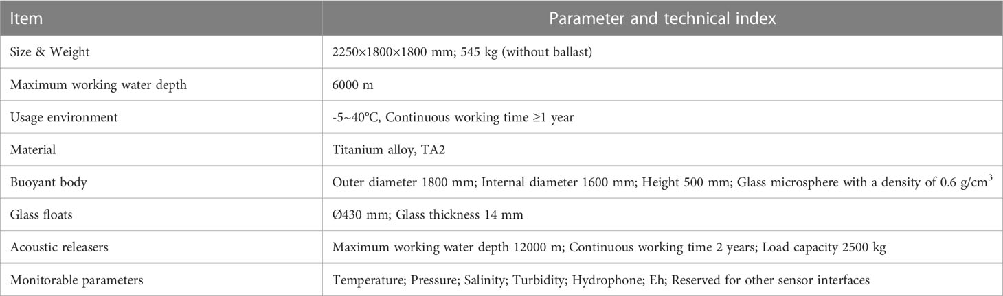
Table 1 Technical indexes of 6000-meter double decelerating lander.
2.1. Equipment configuration
The schematic and physical diagram of the new lander is presented in Figure 1. It comprises a deep-sea landing platform and a marine multi-parameter monitoring unit. A lander frame, a buoyant body, eight glass floats, a ballast, two acoustic releasers, an iridium beacon, a flash beacon, and an Ultra-Short Baseline (USBL) make up the deep-sea lander platform. The marine multi-parameter monitoring unit consists of a CTD, a Hydrophone, a lamp, a camera, an attitude indicator, and a battery tank, as shown in Figure 2A.

Figure 1 The 6000-meter Double Decelerating Lander.
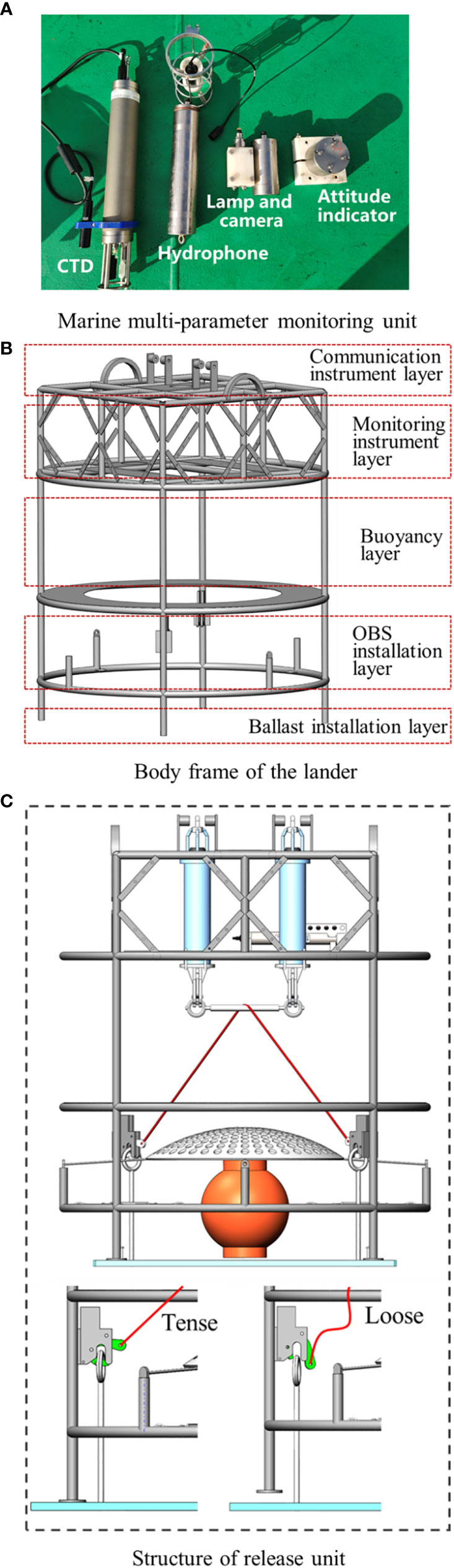
Figure 2 Parts of the lander. (A) Marine multi-parameter monitoring unit; (B) Body frame of the lander; (C) Structure of release unit.
The new lander’s construction and instrument configuration are optimized based on the conventional lander. The lander’s frame is constructed from titanium alloy. The communication instrument layer, monitoring instrument layer, buoyancy layer, OBS installation layer, and ballast installation layer are stacked sequentially from top to bottom of the lander, as seen in Figure 2B. The combination of a buoyancy component and a glass floating ball to create a deep-sea floating unit is used for the new lander in order to improve the lander architecture, heighten the equipment floating center, and lengthen the distance between the barycenter and the buoyancy center. Considering hydrodynamic conditions and the lander frame, the Buoyancy component, made of a hollow glass microsphere with a density of 0.6 g/cm3, is designed as a ring. Each glass float weighs 17.2 kg in the air and can provide 26 kg of buoyancy in water.
2.2. Release unit and recovery method
According to Figure 2C, the release unit comprises an acoustic releaser, a connecting mechanism, ballast, and other components. The major purpose of the release unit is to convert the tool into a gravity-based apparatus so that the lander may rapidly descend to the ocean floor. The ballast is consistently released in response to an auditory signal, enabling the lander to ascend swiftly to the water’s surface.
Two acoustic releasers in parallel coupling to release ballast are designed to improve the success rate of recovery. The acoustic releaser is mounted at the top of the frame without obstruction, allowing stable reception of control signals from the sea surface. The releaser has a 2.5 t effective load capacity. A ballast system is fitted at the frame’s base. The ballast is intended to make handling and installation easier and lessen the lander’s tendency to sink in the silt. The integrated ballast’s design also makes it easier to retrieve the lander without any bumps from the sediments.
The cable is attached to the ballast hooks at the two legs through the connecting bar, which is controlled by two releasers, according to the connection technique for the ballast. When the acoustic release is secured, the cable is tightened; however, when any of the acoustic releases are unlocked, the connecting rod detaches, and the cable slackens. The fixed locations at the frame’s legs allow for the rotation of the hooks around them. The hook holds the ballast in place when the cable is tight; when the cable is free, the hook will open, and the ballast will be discarded.
2.3. Double decelerating structure and method
In order to protect some special sensors, such as OBS, the function of double decelerating is added to the lander. Despite being delicate, the OBS must make touch with the seafloor surface in order to function. A unique design is designed for the deployment of OBS in order to prevent harm to the OBS device when the lander reaches the bottom. The OBS is positioned on the lower portion of the lander, as depicted in Figure 3, and a flexible cable connects it to the bracket. The OBS is subjected to higher fluid resistance as the lander descends, as seen in Figure 3, which causes the cable to be tensioned and the OBS to move upward concerning the lander. After the lander lands, the OBS descends slowly by gravity. During the descent, there will be no impact to ensure that the OBS is not destroyed. In addition, the cable connecting the OBS should not be too long to minimize mutual cable entanglement, which might prohibit the releaser from releasing the ballast and prevent the OBS from clashing with other devices when going up. With the design of the limit net, the OBS will not cross the limit net, avoiding the collision between OBS and other devices.
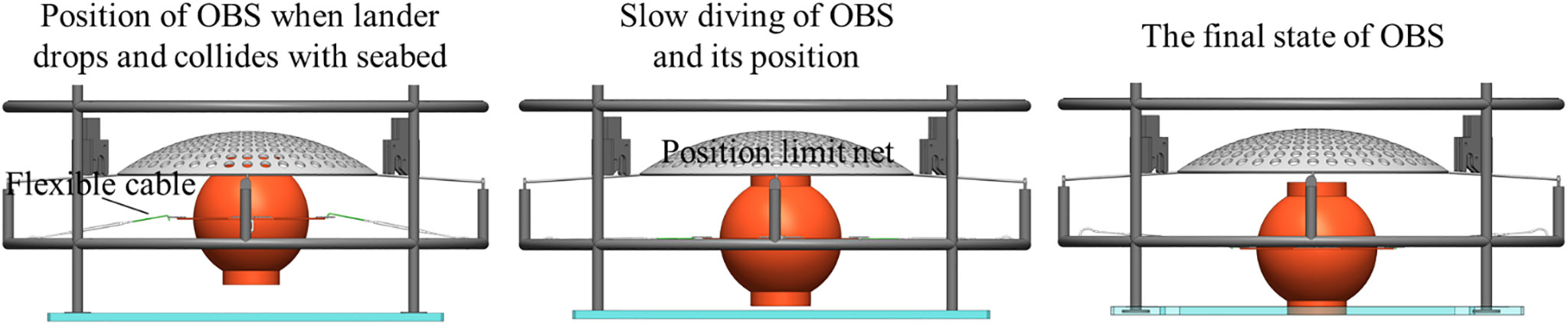
Figure 3 The working process of the double decelerating structure. OBS moves upwards as the lander drops and collides with the seabed, and cables tighten; OBS descent gradually slows after the lander lands; The lander collides with the seabed at an acceptable speed.
3. Static analysis
The force applied to the lander by the different instruments must not be more than the strength of the frame material to ensure the lander’s safe operation. As a result, the ANSYS performs the static analysis of the lander frame.
The analysis follows these steps, as shown in Figure 4: (a) The Static Structural of the ANSYS workbench is selected. Set the material to Titanium Alloy when importing the framework model; (b) Set the connection type at each welding point of the bracket to Bonded, not allowing relative sliding or separation between surfaces or lines of the parts; (c) Tetrahedrons are selected for meshing. For automated grid refinement, set Relevance Center to Fine. Set the smoothing to a high value, consider the nodes nearby, and smooth the grid’s iterative processing. Set the Span Angle Center to Fine to fine-tune the edge mesh such that the span angle varies from 12° to 36°. Only Sizing and Contact Sizing are introduced during the scaffold analysis. The grid is formed when the configuration is complete; (d) Apply loads in the setup after meshing. Four outriggers are set as fixed points, and 5000N is applied to two lugs, respectively. According to the predicted component weight, additional forces are applied at the installation location, as illustrated in Figure 5; (e) Start to solve, including Equivalent Stress, Equivalent Strain, and Maximum Strain.
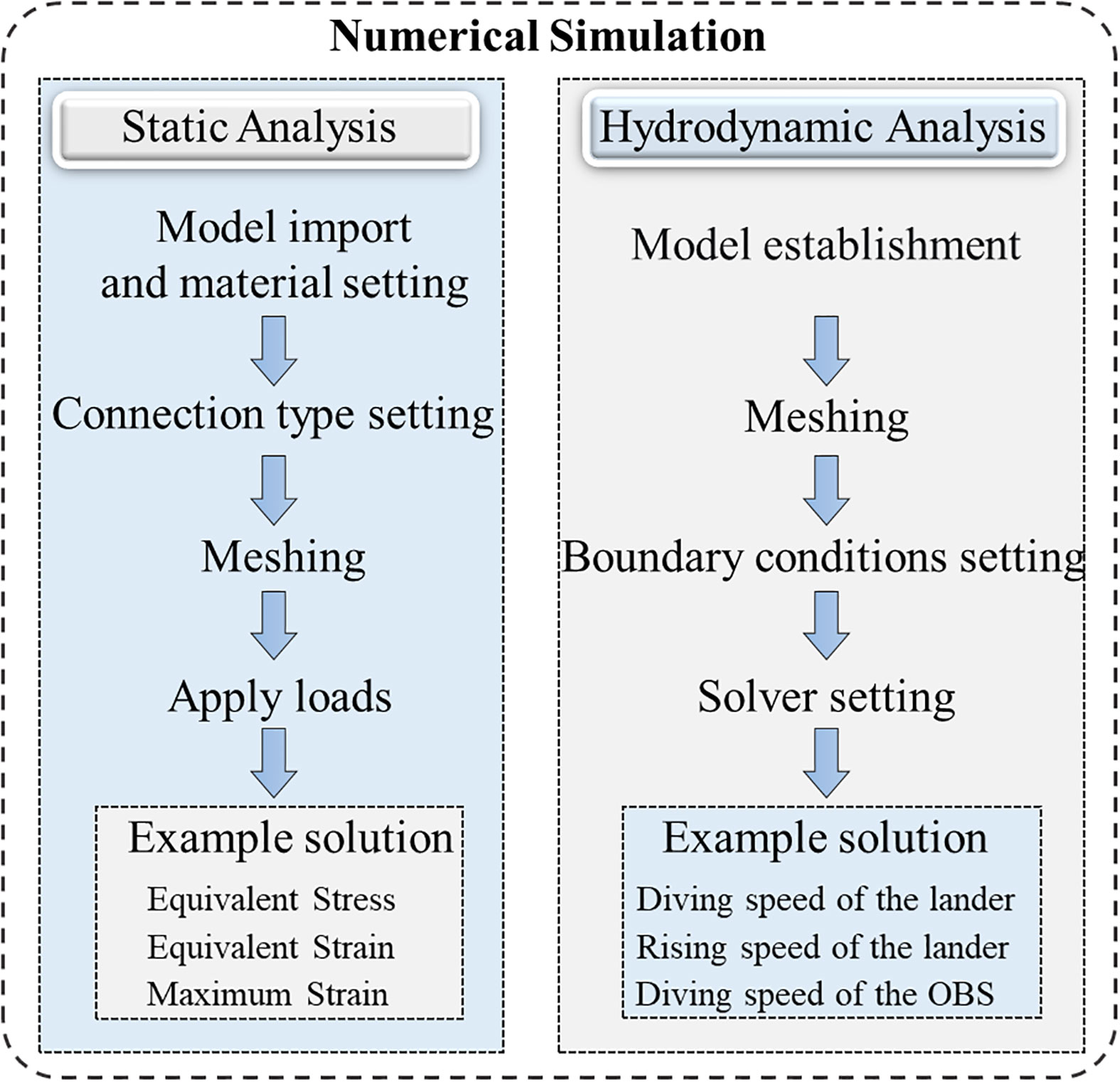
Figure 4 Numerical simulation flowcharts.

Figure 5 Load distribution.
The static analysis of the lander frame is shown in Figure 6. According to the analysis’s findings, the battery cabin’s support plate is under maximum stress of 177.49 MPa, which is significantly less than the 373 MPa yield strength of TA2 titanium alloy. The battery compartment support plate also experiences the most strain. The lander frame can only deform a maximum of 5.8 mm, which falls within the acceptable deformation limit. According to the findings of the static study, the lander frame’s design is sound and can accommodate several pieces of equipment.
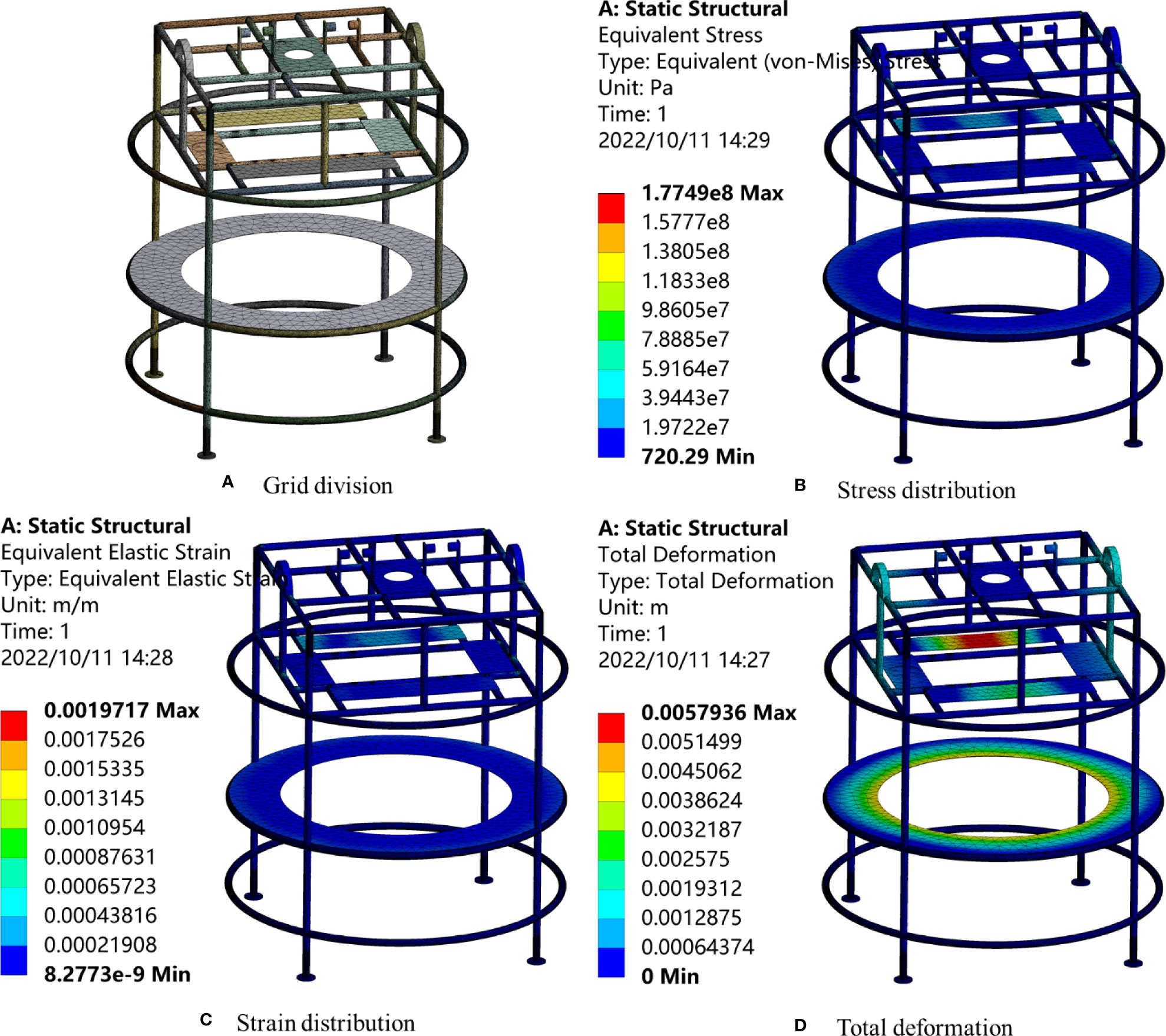
Figure 6 Static analysis of lander frame. (A) Grid division; (B) Stress distribution; (C) Strain distribution; (D) Total deformation.
4. Simulation analysis and calculation of lander
The lander is affected by gravity and current resistance in the water. Fluent software performs the hydrodynamic study of the lander, including examining the lander’s dive, increasing speed, and double decelerating to determine its operational condition.
4.1. Numerical simulation scheme
The hydrodynamic analysis of the lander is carried out by Fluent software, and the numerical simulation flowchart is shown in Figure 4. The steps are as follows: (a) Model establishment. The lander’s three-dimensional model is imported into ICEM, and the Repair Geometry function is used to correct the model tolerance. To ensure model fidelity, Build Topology’s tolerance is set to 0.002. The topology is chosen in Build Body. To construct the Body, select every bounding Surface, then assign the Body to the flow field. To establish the boundary conditions, choose to Create/Modify the Surface and give each bounding surface a name; (b) Meshing. To fine-tune the mesh, the Scale factor is set to 0.1 in Global Mesh Setup. The grid near the device is tight, and the grid distant from it is sparse thanks to variable mesh size choices, which can increase the accuracy and speed of calculations. Tetrahedral meshes without structures enable the model’s spatial discretization. After the mesh is created, Smooth Elements Globally does the mesh smoothing; (c) Boundary conditions setting: Import the 3D mesh file into Fluent. In the General module, select Solver Type as Pressure-Based, and set Solver Time as Steady. Set the realizable k-epsilon model as the viscous model in Models. In Materials, create a fluid medium called water-liquid. Associate the body with water-liquid under cell zone conditions. The wall boundary condition in Boundary Conditions is symmetrical, while the equipment boundary condition is the wall. Set the lander’s weight or buoyancy appropriately, activate gravity, and set the inlet boundary condition to Velocity Inlet with the Velocity Magnitude set to 0 m/s. This allows the lander to fall or float in the water freely; (d) Solver setting. The SIMPLE approach is used for the pressure-velocity coupling solution. Least Squares Cell Based, Second Order, Second Order Upwind, and Momentum processing are utilized for the spatial discretization of gradient, pressure, and momentum. The terms “Turbulent Kinetic Energy” and “Turbulent Dissipation Rate” are both Upwind First Order; (e) Example solution. When solving, the number of iteration steps is set to 10000.
4.2. Analysis of lander diving and rising
When the lander is launched, it will be moved horizontally by ocean currents. The lander’s landing speed should be as quick as possible to guarantee a minimal horizontal displacement and that the lander’s landing position matches the preset location. On the other side, if the speed is too high, the lander damages itself as it rests on the seafloor and hits bottom. In order to ensure the safety of the lander, according to Li et al. (2013), the landing speed at 0.8 ~ 1.2 m/s is recommended.
Rough accounting of the various components of the lander, as shown in Table 2.
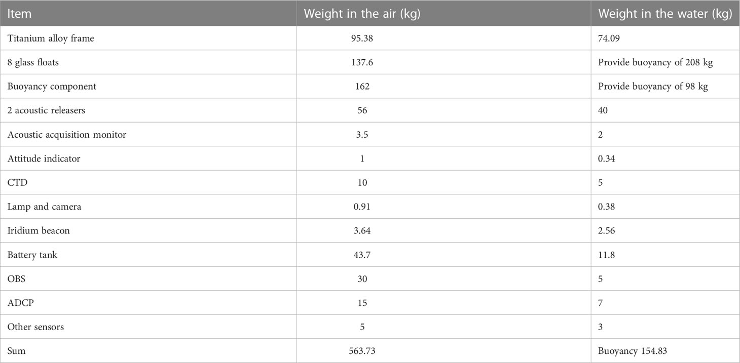
Table 2 Lander weight and buoyancy estimation.
Furthermore, a ballast of 305.34 kg in the water is installed when the lander is deployed. According to this formula
Where, F = force; Cd = fluid resistance coefficient; ρ= density of water; v = speed; S = the cross-sectional area of the lander. After calculation can be obtained:
Import the meshed model into FLUENT as illustrated in Figure 7. The lander’s overall weight is set to 150 kg for the simulation of its fall, which is the weight remaining after deducting its buoyancy, and its upward buoyancy is set to 155 kg for floating. According to the simulation results, the lander’s constant diving speed and rising speed in the water are both about 1 m/s, and the results are shown in Figure 8.
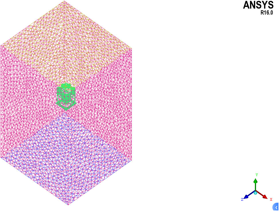
Figure 7 Simulation grid division.
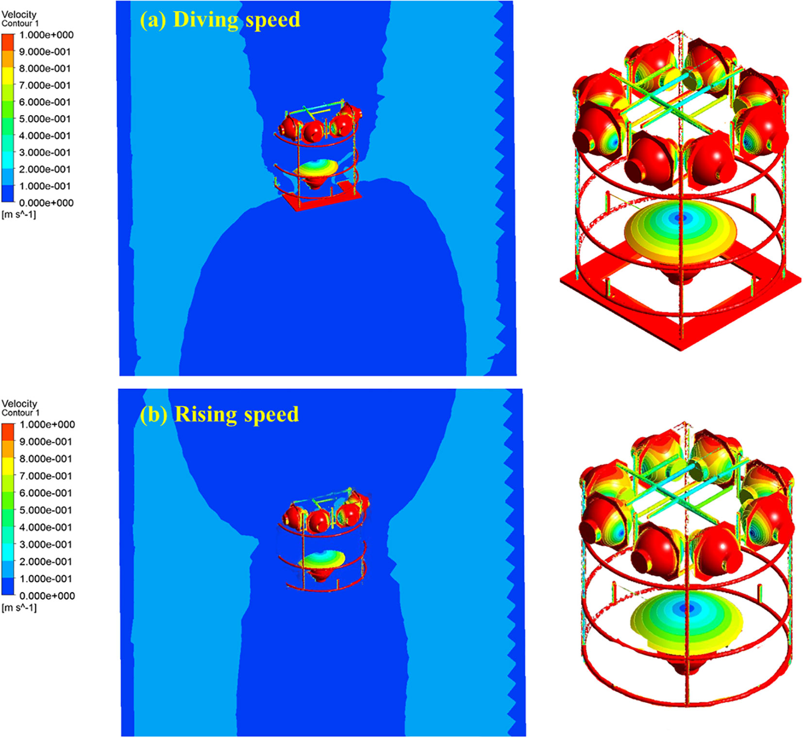
Figure 8 Simulation results of lander diving and rising speed. (A) Diving speed; (B) Rising speed.
The lander can travel at a maximum speed of 0.982 m/s when it strikes the bottom and 0.997 m/s when it reaches the water’s surface. For around 102 minutes, the lander descends to a water depth of 6000 m. For approximately 100 minutes, the lander rises to the sea’s surface. The simulation and calculation outcomes are nearly identical.
4.3. Simulation of double decelerating
The sensing instrument of OBS is all installed in a glass ball placed in a plastic shell. Therefore, the impact resistance of OBS is weak. On the other hand, in addition to the internal sensor balance, OBS must be in close touch with the seabed to correctly transform ground motion impulses into electrical signals and collect them. The gathered signal could be inaccurate if there is inadequate coupling between OBS and the seafloor. As a result, OBS cannot move too slowly when it touches the seafloor, or the coupling between OBS and the seafloor would be weak. OBS’s deployment experience indicates that a speed of 0.5 to 0.8 m/s can guarantee a good connection between the device and the seafloor.
The traditional OBS deployment method is to fix the ball on the steel frame, and there will be a buffer spring between the OBS and the steel frame, as demonstrated in Figure 9. When the OBS is deployed, throw the steel-framed OBS into the water, where it will fall under gravity at a speed of 1 to 1.5 m/s. When an OBS with a steel frame strikes the seafloor, the steel frame’s speed decreases to 0 m/s from its diving speed. As it moves and compresses the spring, the OBS will continue to shield itself from harm. Although the descending speed of 1 to 1.5 m/s may guarantee that the lander’s landing spot is near the predetermined area, it will also result in OBS damage, mainly if the landing site’s sediment is complex or the landing site is rock.
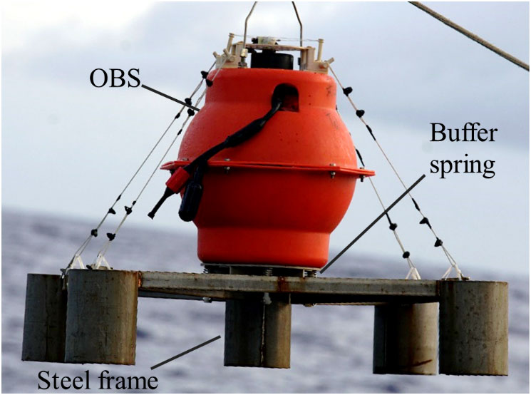
Figure 9 Traditional OBS structure (accessed http://oil.igg.cas.cn/gb2019/hddzy/hddzyobs/, 2019).
When the OBS is mounted on the lander, the steel structure beneath it is no longer attached. The OBS is susceptible to damage when it collides with the seafloor directly without any protection. The lander’s fall speed, which can assure a safe landing, is roughly 1 m/s, according to the findings of section 4.2. However, OBS might sustain damage if it strikes the seafloor at a speed of 1 m/s since the material’s strength differs from the lander’s. Therefore, to achieve the safe deployment of OBS, the lander is designed with the unit of decelerating landing, as described in Section 2.3.
The local simulation of the OBS installation layer is performed to verify the double decelerating’s effectiveness. The simulation results show that when the lander is descending, the descent speed is 1 m/s. The OBS sphere’s bottom lines up with the bottom of the lander when it is tightly attached to the frame. The OBS collides with the seafloor as the lander sinks to the bottom, and as it does so, its velocity drops from 1 m/s to 0, creating an impact force. The OBS is attached to the lander frame in this arrangement by a flexible cable moving upward relative to it when the water uplift force acts on it. Restricted by the length of the cable and the limiting net, the OBS stabilized after an upward displacement of 160 mm, as shown in Figure 8A and Figure 10, and then diving at 1 m/s with the lander. As illustrated in Figure 11, OBS’s speed steadily reduces once the lander stops moving because of its gravity until it makes contact with the seafloor surface at a speed of 0.55 m/s. During the OBS deployment, there is no impact force, ensuring the safe placement of OBS balls.
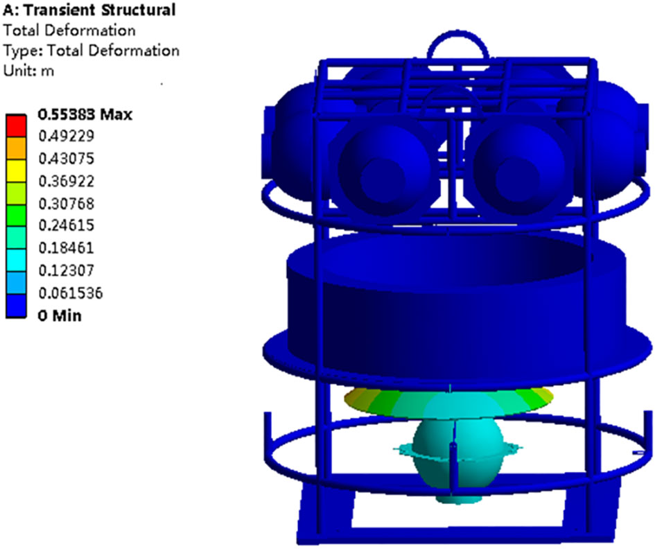
Figure 10 Simulation of the double decelerating landing of the lander.
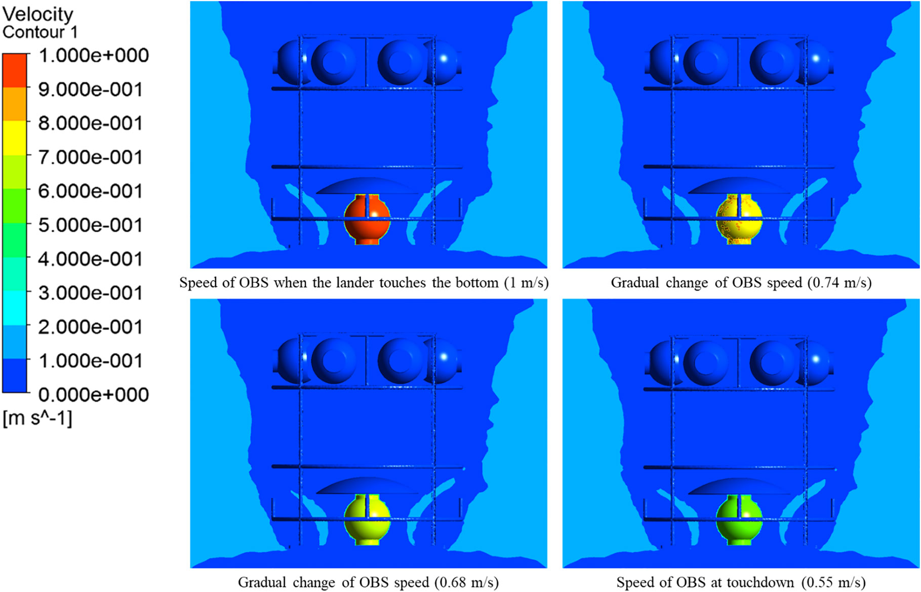
Figure 11 Simulation results of OBS speed when it contacts with the seabed.
5. Field application
Two field applications of the lander were carried out, as shown in Figure 12. In one of the actual applications, the lander functioned at a depth of 2,240 m for 75 hours. In a second application, the lander submerged for 45 hours at a depth of 1,790 meters. Two successful applications have proved that the characteristics and technical indicators of the lander are adequate. The lander’s acoustic communication capabilities, free landing and surfacing, and acquisition performance in deep water were evaluated in a field application. In both applications, the monitoring equipment successfully obtained deep-sea in-situ data. The application site is shown in Figure 13.
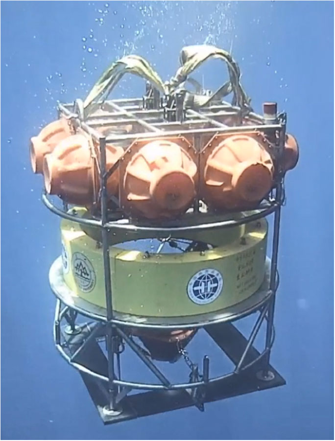
Figure 12 Underwater photography of lander.
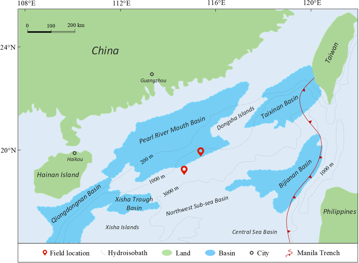
Figure 13 Overview of field application location and surrounding area (modified from Cui et al., 2022).
Before the sea trial, all sensors on the lander were calibrated, and the lander underwent Special detection and general testing, including compressive strength testing, sealing testing, self-testing, and electromagnetic compatibility testing. In the field application, the operation phases consist of lander inspection, equipment assembly and testing, lander deployment, underwater operations, and lander retrieval.
Seafloor temperature, salinity, Eh, turbidity, underwater acoustic environment, and OBS data were successfully monitored in both field applications, which the corresponding data is not displayed because of confidentiality. As depicted in Figure 14, the attitude of the lander is steady during a dive, with little fluctuation in azimuth, pitch, and roll angles. The cylindrical chamber in the center of the lander promotes the flow of water from bottom to top (top-down when rising) and preserves the lander’s attitude stability during deployment or recovery. In Section 4.2, the diving and rising velocities of the lander are calculated to be 0.982 m/s and 0.997 m/s, respectively. As illustrated in Figure 15, the lander measured diving and ascending speeds of 0.925 m/s and 0.9335 m/s, respectively, commensurate with the design speed. The difference between the actual speed and the calculated speed may be due to the simple formulas used in the calculation, and the numerical settings for parameters also need to be improved.
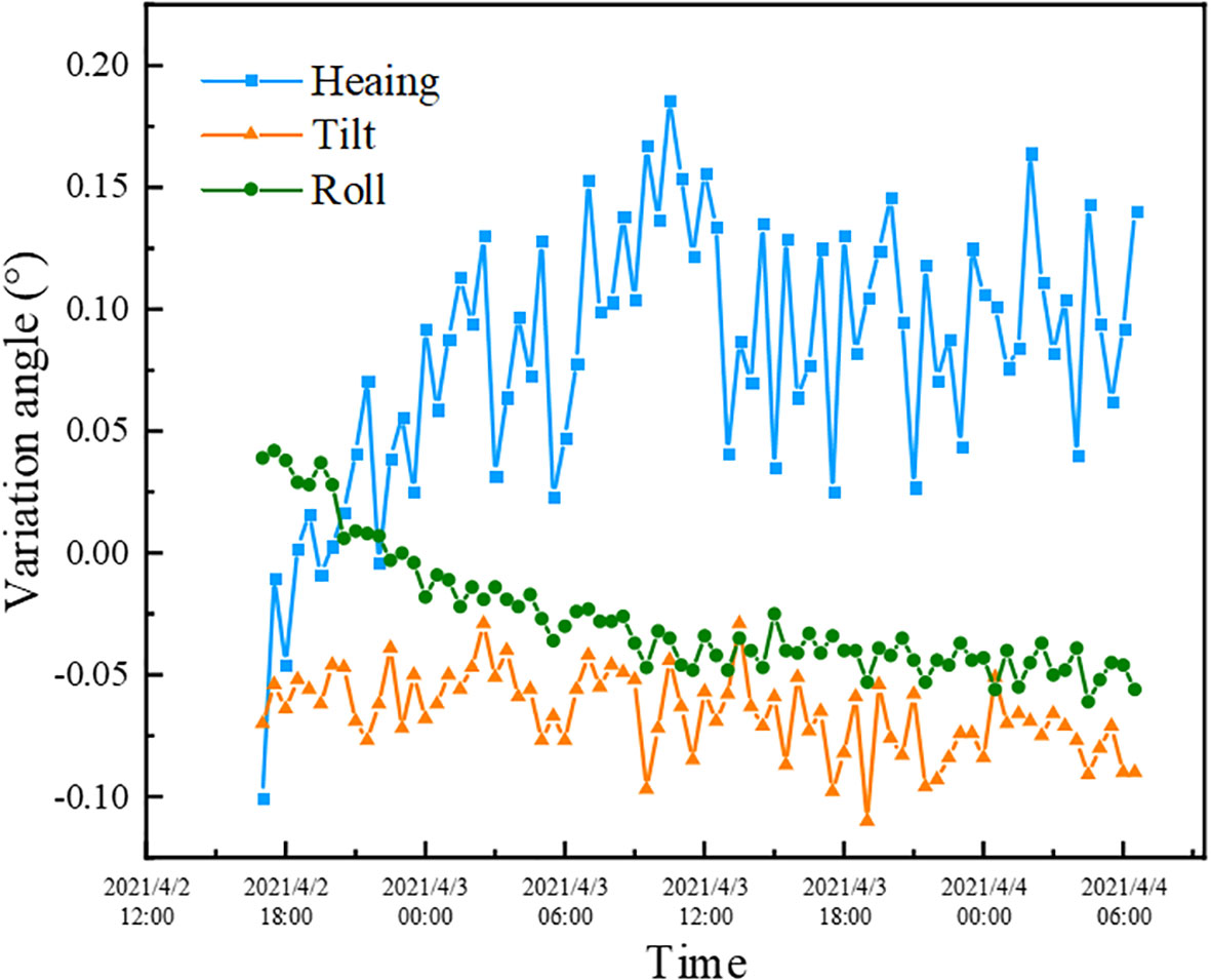
Figure 14 Attitude change of lander during diving.
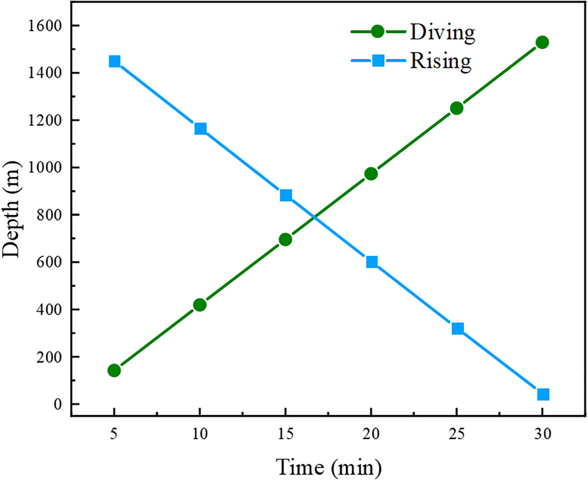
Figure 15 The depth change of the lander during the diving and rising.
After two applications in the deep-sea, it shows that the lander can be used under deep-sea circumstances. The lander deployment and recovery are stable, and the in-situ monitoring task can be successfully completed, indicating that the lander design is successful.
6. Conclusions
A new double decelerating lander was successfully developed. The lander’s design meets the installation and working requirements of various instrumentation devices, especially the design of double decelerating achieve the safe deployment of OBS and other equipment that must be in contact with the seabed. Optimizing the release structure improves the success rate of decoupling release counterweight. Simulation research demonstrates that the structural strength of the lander is sufficient, and the motion parameters of the lander during deployment and recovery are determined. Two field applications were successfully carried out, and various in-situ data in the deep sea were obtained, achieving the goal of long-term in-situ monitoring. The simulation results and field applications prove that the diving speed of the developed lander meets the design and safety requirements, and can also protect the OBS device. A feasible technical means for deep-sea in-situ monitoring have been proposed, and the double decelerating lander has also expanded the technical system of marine environmental investigation.
Data availability statement
The original contributions presented in the study are included in the article/Supplementary Material. Further inquiries can be directed to the corresponding author.
Author contributions
LG and XY: Methodology, Formal analysis, Writing - Original Draft, Writing - Review & Editing. GX: Review & Editing. CW, ZF, and SZ: Formal analysis. YL: Visualization. KL and YY: Supervision. All authors contributed to the article and approved the submitted version.
Funding
This research was funded by the National Natural Science Foundation of China (NSFC) (No.U2006213) and Laoshan Laboratory (No. LSKJ202203505).
Conflict of interest
The authors declare that the research was conducted in the absence of any commercial or financial relationships that could be construed as a potential conflict of interest.
Publisher’s note
All claims expressed in this article are solely those of the authors and do not necessarily represent those of their affiliated organizations, or those of the publisher, the editors and the reviewers. Any product that may be evaluated in this article, or claim that may be made by its manufacturer, is not guaranteed or endorsed by the publisher.
References
Berelson W. M., Buchholtz M. R., Hammond D. E., Santschi P. H. (1987). Radon fluxes measured with the MANOP bottom lander. Deep Sea Res. Part A Oceanographic Res. Papers 34 (7), 1209–1228. doi: 10.1016/0198-0149(87)90072-0
Black K. S., Fones G. R., Peppe O. C., Kennedy H. A., Bentaleb I. (2001). An autonomous benthic lander: Preliminary observations from the UK BENBO thematic programme. Continental Shelf Res. 21 (8-10), 859–877. doi: 10.1016/S0278-4343(00)00116-3
Chen Z., Li J., Li X., Chen S., Dasgupta S., Bai S., et al. (2020). Characteristics and implications of isoprenoid and hydroxy tetraether lipids in hadal sediments of Mariana and yap trenches. Chem. Geol. 551, 119742. doi: 10.1016/j.chemgeo.2020.119742
Chen J., Zhang Q. F., Li J. (2017). Research on the application of the hadal lander technology in the Mariana trench. J. Ocean Technol. 36 (1), 63–69.
Cui Y., Guo L., Liu T., Yang Z., Ling X., Yang X., et al. (2022). Development and application of the 3000 m-level multi-parameter CPTu in-situ integrated test system. Mar. Geores Geotechnol. 1-12. doi: 10.1080/1064119X.2022.2053008
Duineveld G., Lavaleye M., Berghuis E., De Wilde P. (2001). Activity and composition of the benthic fauna in the whittard canyon and the adjacent continental slope (NE Atlantic). Oceanol. Acta 24 (1), 69–83. doi: 10.1016/S0399-1784(00)01129-4
Hardy K., Cameron J., Herbst L., Bulman T., Pausch S. (2013). “Hadal landers: the DEEPSEA CHALLENGE ocean trench free vehicles,” in 2013 OCEANS-San Diego (San Diego: IEEE), 1–10.
Jamieson A. J., Fujii T., Solan M., Priede I. G. (2009). HADEEP: Free-falling landers to the deepest places on earth. Mar. Technol. Soc. J. 43 (5), 151–160. doi: 10.4031/MTSJ.43.5.17
Lavaleye M., Duineveld G., Lundälv T., White M., Guihen D., Kiriakoulakis K., et al. (2009). Cold-water corals on the tisler reef: Preliminary observations on the dynamic reef environment. Oceanography 22 (1), 76–84. doi: 10.5670/oceanog.2009.08
Li J., Xu J., Liu Z. (2013). Applications of tripods to deep-Sea observation. Adv. Earth Sci. 28 (5), 559–565.
Oevelen D. V., Duineveld G., Lavaleye M., Mienis F., Soetaert K., Heip C. H. (2009). The cold-water coral community as hotspot of carbon cycling on continental margins: A food-web analysis from rockall bank (northeast Atlantic). Limnol. Oceanography 54 (6), 1829–1844. doi: 10.4319/lo.2009.54.6.1829
Person R., Aoustin Y., Blandin J., Marvaldi J., Rolin J. F. (2006). From bottom landers to observatory networks. Ann. Geophysics 49 (2-3), 581–593. doi: 10.4401/ag-3122
Podolskiy E. A., Murai Y., Kanna N., Sugiyama S. (2021). Ocean-bottom seismology of glacial earthquakes: The concept, lessons learned, and mind the sediments. Seismol. Res. Lett. 92 (5), 2850–2865. doi: 10.1785/0220200465
Rowe G. T., Boland G. S., Briones E. G. E., Cruz-Kaegi M. E., Newton A., Piepenburg D., et al. (1997). Sediment community biomass and respiration in the northeast water polynya, Greenland: a numerical simulation of benthic lander and spade core data. J. Mar. Syst. 10 (1-4), 497–515. doi: 10.1016/S0924-7963(96)00065-6
Schlindwein V., Kirk H., Hiller M., Scholz J. R., Schmidt-Aursch M. (2022). GAKKELDEEP: DEPAS ocean-bottom seismometer operations at the gakkel ridge in 2018-2019.
Tahey T. M., Duineveld G. C. A., DeWilde P. A. W. J., Berghuis E. M., Kok A. (1996). Sediment O-2 demand, density and biomass of the benthos and phytopigments along the northwestern Adriatic coast: The extent of po enrichment. Oceanol. Acta 19 (2), 117–130.
Turchik A. J., Berkenpas E. J., Henning B. S., Shepard C. M., IEEE (2015). “The deep ocean dropcam: A highly deployable benthic survey tool,” in In OCEANS 2015-MTS/IEEE Washington, 1–8.
Witbaard R., Duineveld G. C. A., van der Weele J. A., Berghuis E. M., Reyss J. P. (2000). The benthic response to the seasonal deposition of phytopigments at the porcupine abyssal plain in the north East Atlantic. J. Sea Res. 43 (1), 15–31. doi: 10.1016/S1385-1101(99)00040-4
Wu H., Tan C., Jin B., Yang C., Chen Y. (2011). Design of an energy supplying device for equipments for in-situ detection of deep-sea hydrothermal fluid. Mar. Sci. 35 (02), 82–85.
Yu X., Yan Z., Zhu M., Li D., Jiang Z., Cui S. (2017). Review of seabed landers for monitoring solute fluxes in deep sea. Mar. Sci. 41 (06), 150–161.
Keywords: lander, double decelerating, in-situ monitoring, numerical simulation, field application
Citation: Guo L, Yang X, Xue G, Wang C, Fei Z, Zhang S, Liu Y, Lu K and Yang Y (2023) Development and application of a 6000-meter double decelerating lander. Front. Mar. Sci. 10:1090940. doi: 10.3389/fmars.2023.1090940
Received: 06 November 2022; Accepted: 09 January 2023;
Published: 23 January 2023.
Edited by:
Yuan Lin, Zhejiang University, ChinaReviewed by:
Xiaolei Liu, Ocean University of China, ChinaXing Zheng, Harbin Engineering University, China
Jiangong Wei, Guangzhou Marine Geological Survey, China
Copyright © 2023 Guo, Yang, Xue, Wang, Fei, Zhang, Liu, Lu and Yang. This is an open-access article distributed under the terms of the Creative Commons Attribution License (CC BY). The use, distribution or reproduction in other forums is permitted, provided the original author(s) and the copyright owner(s) are credited and that the original publication in this journal is cited, in accordance with accepted academic practice. No use, distribution or reproduction is permitted which does not comply with these terms.
*Correspondence: Xiuqing Yang, eXhxc2VsZkAxNjMuY29t