 Shuaidong Yang1,2
 Mi Zhou
 Xihong Zhang
- 1College of water Conservancy and Hydropower Engineering, Hohai University, Nanjing, China
- 2Hydraulic Engineering Research Institute, Pearl River Water Resources Research Institute, Guangzhou, China
- 3Research Assistance, State Key Laboratory of Subtropical Building Science, South China Institute of Geotechnical Engineering, South China University of Technology, Guangzhou, China
- 4Engineering Business Department, Guangzhou Construction Engineering Corporation Limited, Guangzhou, China
- 5Earthquake Engineering Research & Test Center, Guangzhou University, Guangzhou, China
- 6Associate professor (PhD), School of Marine Science and Engineering, State Key Laboratory of Subtropical Building Science, South China Institute of Geotechnical Engineering, South China University of Technology, Guangzhou, China
- 7School of Civil and Mechanical Engineering, Curtin University, Bentley, PH, Australia
An extensive investigation on the performance of large geotextile mat dykes on stiff-over-soft soil deposits is carried out undertaken through numerical simulation in this paper. The large mat is reinforced by geotextiles with a new type of arrangement, i.e. non-uniform geotextile reinforcement. The numerical model is validated against centrifuge test data and other previously testing results, prior to conduct parametric study. It is found that large geotextile reinforced dykes on sand overlying clay fails through a global mechanism that the whole dam sank downwards together. It is found that the thickness of the sand layer, the width of the dyke base, and the shear strength of soft clay are the key influence factors on the stability of the dyke. A design flow chart is then proposed to quantity the performance of the geotextile mat dyke with non-uniform reinforcement, in terms of predicting allowable dyke fill height and the corresponding safety factor, which can be employed to provide refer for its design and construction.
1 Introduction
With the development of the coastal areas and the port construction in China, the number of land reclamations and man-made islands are increasing gradually. Numerous temporary dykes for these projects have been constructed or underway near coastlines or over rivers in recent years (see Figures 1A, B). Geotextile reinforced dykes (or named geotextile mat dykes) have been popularly used because of their attractive characters such as fast construction, high stability, maturity of the technology and especially economical feature. The dykes are formed by multi-layered mats which are made of sewing geotextiles and filled with sand or stabilized soil. In engineering practise, they are more popular comparing with traditional dykes, i.e. cement mortars, concrete dykes (Chu et al., 2011; Morán and Toledo, 2011; Guo et al., 2013; Orendorff et al., 2013; Guo et al., 2015). Due to the nature of the soft soil deposits, the soil has some characters such as fine particle, high moisture content, high compressible and extremely low strength. To improve the stability of the foundation, the large dimension of the dykes on soft ground is required to suit for the low bearing capacity of original foundation. And the reinforcement of geotextile makes the dykes as flexible structures which similar to embankments, slopes and retaining walls broadly reinforced by geotextiles to enhance their stabilities (Borges and Cardoso, 2002; Yan et al., 2009; Wang et al., 2011; Zhang et al., 2015). The geotextile reinforced dykes are used for an increasing range of application in hydraulic, marine, and environmental engineering to prevent the collapse of sand fill (Lawson, 2008; Liu and Yan, 2012). Nevertheless, the failure mechanism for geotextile mat dykes is still not properly understood (Yan et al., 2009). And there is no design guide for engineers to follow. Consequentially, a series of failure cases were recently reported due to the uncertainty on the failure mechanisms. The case study of Wei et al. (2013) investigated the failure mechanism of the geotextile reinforced dyke used in Shenjiamen Port (Zhoushan, China). The geotextile reinforced dyke was applied in an undersea tunnel excavation construction and failed in the process of sand filling of the ninth mat with whole dyke sinking in the centre as shown in Figure 1C. Another case study of Peng et al. investigated the application of geotextile reinforced dyke in Tianjin Port (Tianjin, China) for a sea reclamation. The dyke failed while the construction near completion with a standing ridge along the centre of the dam and the sunk part on the dam side as shown in Figure 1D. It is urgent to have a comprehensive understanding of the failure mechanism and design guide for large geotextile mat dykes.
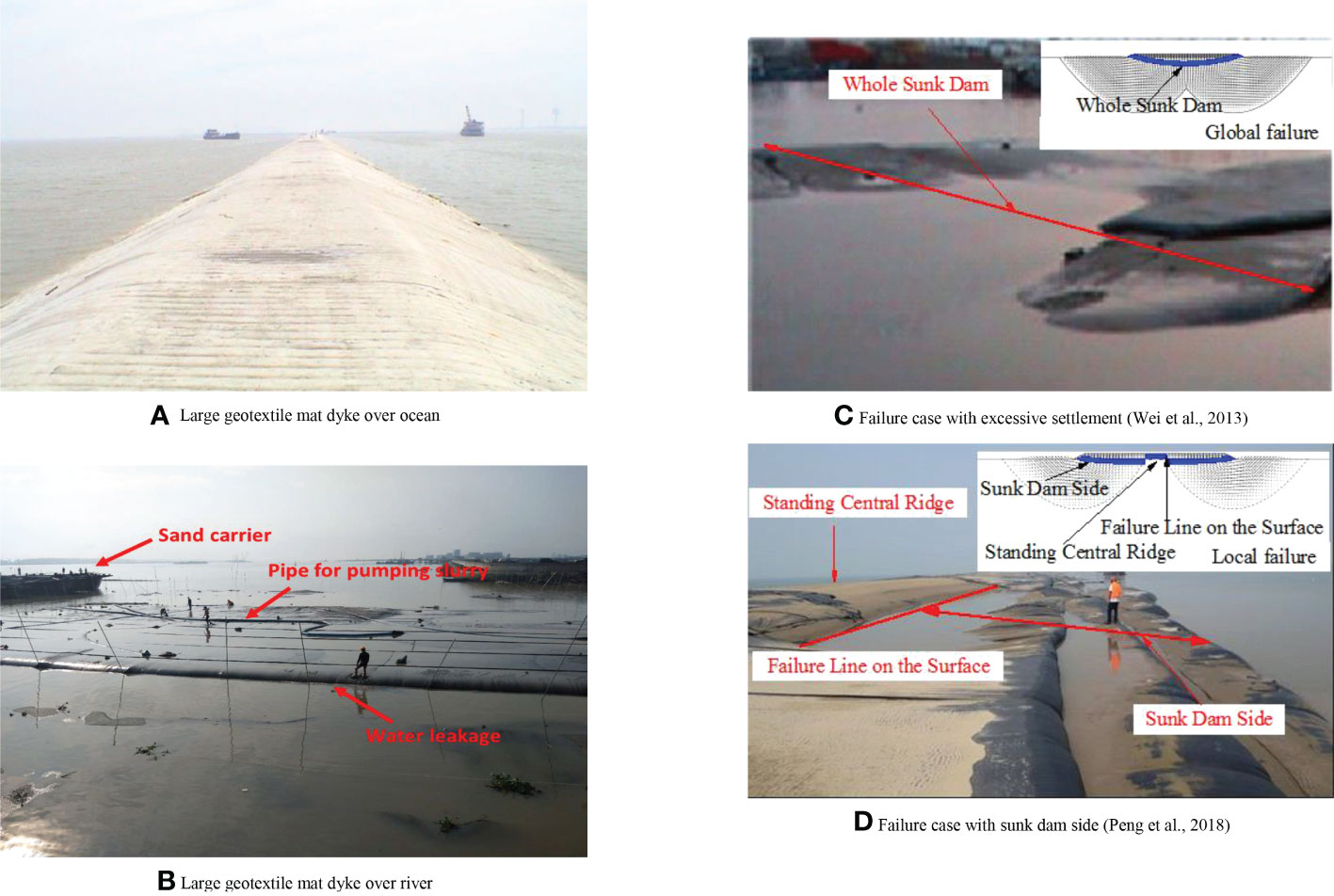
Figure 1 Geotextile mat dyke and failure cases: (A) large geotextile mat dyke over ocean; (B) large geotextile mat dyke over river; (C) failure case with excessive settlement (Wei et al., 2013); (D) Failure case with sunk dam side (Peng et al., 2018).
Soil dykes are commonly constructed by stacking layers of large geotextile mats with the thickness about 0.5 m for each layer. The mats are made of geotextiles and filled with sands or sandy soils in a slurry form by pumping the slurry into the mat shaped pockets (see Figure 1B). The width of the bottom layer of mats (W) can be arranged from 10 m to 120 m in practice. The filling height of the whole dykes (H) usually ranges from 2.5 to 10 m with side slopes of K = 1/1~1/3. When the dyke is constructed on soft soils, the tensile stress of geotextiles at the bottom layer are usually much larger than those of at the top, which hence leads to failure due to insufficient tensile strength at the bottom of the dyke (see Figure 1C). To solve this problem, a new type of reinforcing method is proposed where the thickness of geotextiles mats are increased nonlinearly from the bottom to the top of the dyke, with the principle of more uniform tensile stress/strain developed in each layer of geotextiles, so as to enhance the stability of the dykes.
In attempt to study the stability and deformation behaviors of large geotextile mat dykes, a few centrifuge and field tests were conducted on geotextile mat dykes reinforced with the traditional reinforcement method (with uniform thickness of geotextile mat) on soft soils (Shin and Oh, 2004). Some numerical analyses were carried out to provide insight into the stability of such kind of dykes (Yan et al., 2009; Peng et al., 2018). The performance of geotextile mats on sand overlying clay were studied trough analytical derivations based on experimental results. It is noteworthy that the analytical studies were considered for one layer mat of the dyke with uniform geotextile reinforcement (Chu et al., 2011; Malik and Sysala, 2011; Guo et al., 2015).
However, the failure mechanism and design method for large geotextile mat dykes have not been established (Yan et al., 2009; Wei et al., 2013; Peng et al., 2018), especially for dykes on sand overlying clay, i.e. sand overlying clay, which is a commonly soil profile faced for engineers in offshore engineering (Teh et al., 2008; Arulrajah et al., 2009). Hence it is problematic for engineers to conduct design work because special design guidelines for geotextile mat dykes have not been established and it always were designed by following the successful experience from other similar projects or by the standards for other similar structures (i.e. reinforced embankments).
This study focus on the behaviors of dykes with non-uniform geotextile mats on sand-overlying-clay soil deposits. A numerical model is generated which is validated against available testing results. Parametric study is then conducted to quantify the influence of sand layer thickness below dykes ts, the tensile stiffness of geotextiles J, the width of the dyke base W, the material properties of sand E, φs, and the shearing strength of clay Su. Based on the results of parametric study, two formulas were given to predict quantitatively for the limiting filling height and the safety factor of the non-uniform geotextile mat dykes on sand-overlying-clay soil deposits.
2 Numerical study
2.1 Geometry and parameters
The commercial software ABAQUS (Dassault Systemes, 2012) is employed in this study. In consideration of the geometric properties of the geotextile mat dyke, two-dimensional plane strain model is set in the simulation. Full-section models are generated (see Figure 2A). The bottom boundary of the model is restrained against vertical movement, while the vertical boundaries are retrained against horizontal movement (i.e. Ux = 0 for the left and right sides, and Uy = 0 for the bottom side). Figure 2B illustrated the FE model of the large geotextile mat dyke on the stiff-over-soft soil deposits.
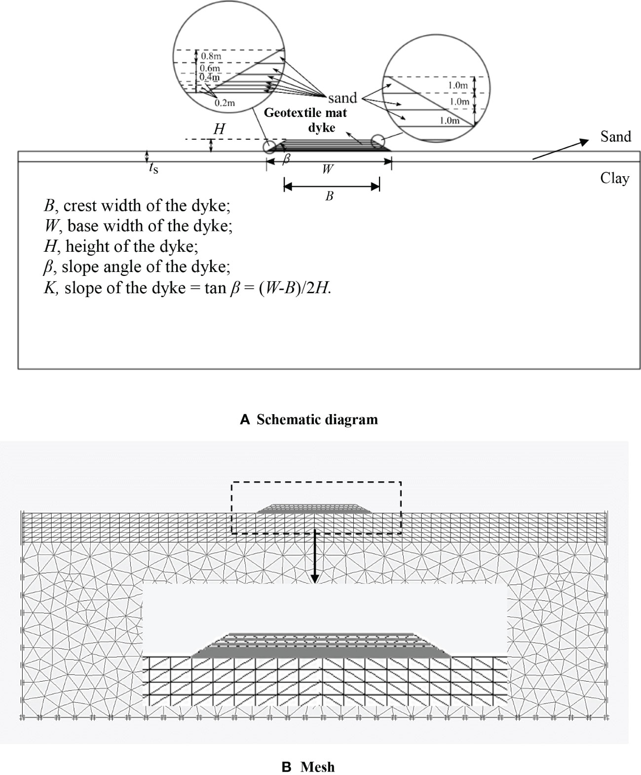
Figure 2 Finite element model of the large geotextile mat dyke on sand overlying clay: (A) Schematic diagram; (B) Mesh.
Mohr-Coulomb model is used for the infill sand fill in the dyke, the underlying sand and clay of the foundation, in which five parameters are required: the cohesion (C), the friction angle (φ), Young’s modulus (E), Poisson’s ratio (ν), and the dilatancy angle (ψ). Considering its high permeability, the infill sand is assumed to be fully drained. For the soft clay in the foundation, undrained analysis is set up to account for its low permeability. The saturated unit weight of the fill sand and the ground sand layer are 19.5 kN/m3 and 21 kN/m3, respectively. The saturated unit weight of clay is 17 kN/m3. A conservative analysis is normally considered with undrained condition for soft clay. This is because clay consolidation normally has a minimal effect during the fast construction process of the dyke. The range of the undrained shear strength of clay is set from 2.5 kPa to 25 kPa. The stiffness ratio of E/Su is kept as a constant of 500 (Tian et al., 2011; Zhou et al., 2013; Zhou et al., 2016). The parameters of all materials involved in this study are selected within practical ranges as shown in Table 1. The ultimate elongation of the geotextile is defined as 10%. For the geotextile mats, they are modelled as a linear elastic material using 2D continuous truss element which can subject tensional force only. A penalty ratio is introduced to define the interaction between the soil and geogrids. A “hard contact” is adopted in the normal direction (i.e. no penetration is allowed), and penalty algorithm is used to define the tangential friction behaviour (see Dassault Systemes, 2012).
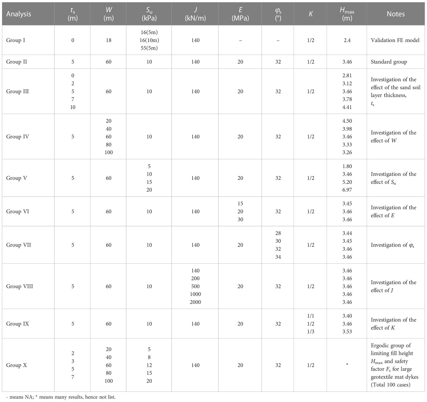
Table 1 Summary of groups of FE parametric study.
Based on the interface shear tests for all different contacts, friction coefficient of the interface between the infill sand and geotextiles is set as αs = 0.6. The frictional coefficient of the interface between the layers of large geotextile mats (i.e. geotextile to geotextile) is set as αg = 0.6. The frictional coefficient of the interface between geotextiles and the foundation is set as αc = 0.5.
Modified direct shear tests were conducted to obtain these roughness parameters. It is to be noted that the parameters of roughness are obtained from laboratory test for the cases as shown in Figure 1B, which is within the practical arranges reported (Anubhav and Basudhar, 2010; Wang et al., 2022).
To simulate the construction process of the dyke, geotextile mat filled with sand are inactivated before the filling process in the numerical simulation. They are then activated layer by layer until the entire filling process is completed. The load of each mat layer is applied to the FE model when it is activated until the dyke collapses or the geotextiles break. The failure of underlying soft clay and the elongation strain of geotextile exceed 10% are the two criteria for defining the failure of a dyke. When one of these criteria is reached, the failure of the dyke is described with Fs = 1.
2.2 Model validation
The above generated FE model is validated against the centrifuge testing data and numerical simulation results reported by Yan and Chu (2010). Table 1 (Group I) summarizes the parameters used in the validation cases. These previous results were carried out to examine the stability of a dyke on layered clay designed for the land reclamation at Tianjin Port, China. In their study, the foundation soil consisted of three layers of clay. The right side of Figure 3A shows the ultimate settlement contours of the dyke and the underlying soil. The left side of Figure 3A gives the results of this study. A good agreement on the soil settlement underneath the dyke can be found between the results by this study and the data reported by Yan and Chu (2010). In addition, the soil flow in the underly (displacement vector plot) as shown in Figure 3B also show close match between this study and the centrifuge testing results.
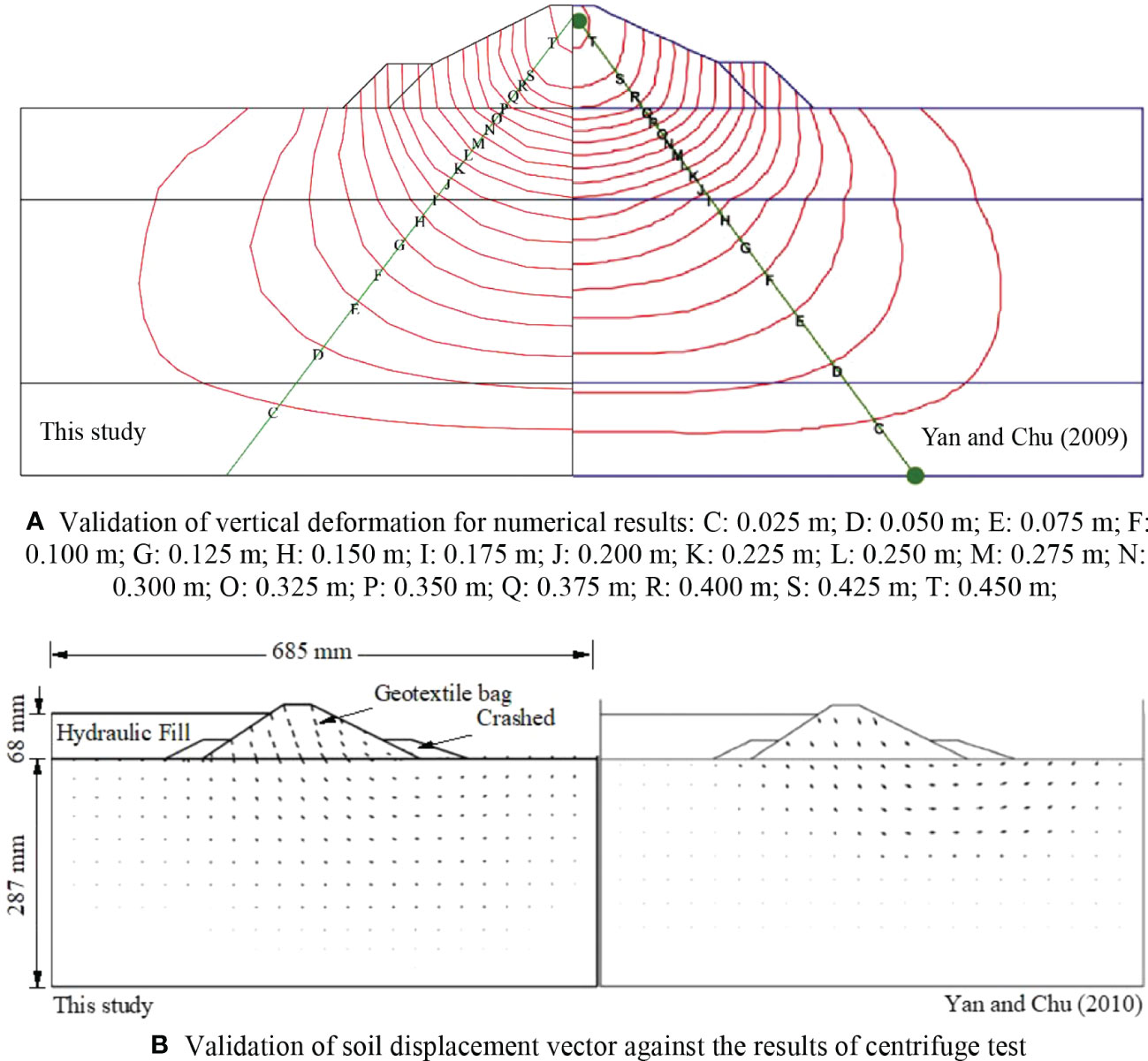
Figure 3 Validation of FE study against the results of Yan and Chu (2010): (A) validation of vertical deformation for numerical results: C: 0.025 m; D: 0.050 m; E: 0.075 m; F: 0.100 m; G: 0.125 m; H: 0.150 m; I: 0.175 m; J: 0.200 m; K: 0.225 m; L: 0.250 m; M: 0.275 m; N: 0.300 m; O: 0.325 m; P: 0.350 m; Q: 0.375 m; R: 0.400 m; S: 0.425 m; T: 0.450 m; (B) validation of soil displacement vector against the results of centrifuge test.
3 Results and discussion
Considering the application scenario and its own characteristics of the geotextile mat dyke on sand-overlying-clay soil deposits, the limiting fill height of the dykes and its failure mechanisms are potentially influenced by the following six factors: (i) the thickness of sand layer below the dykes ts; (ii) the base width of the dyke W; (iii) the shear strength of clay Su; (iv) the sand properties E, φs; (iv) the tensile stiffness of geotextile J; and (vi) the slope ratio of the large geotextile mat dyke K. In this section, these factors are examined. It should be noted that the failure of a dyke is defined at the critical condition with its safety factor of Fs = 1.
3.1 Effect of sand layer thickness below dykes
To explore the influence of the sand layer thickness below the dykes, ts, on the failure mechanisms and the corresponding stability of the large geotextile mat dyke, one group of cases are modelled with varying the sand soil layer thickness ts from 0 m to 10 m, and other parameters are maintained to be the same as tc = 100 m, E = 20 Mpa, φs = 32°, Cs = 0.1 kPa, Su = 10 kPa, W = 60 m, K = 1/2, J = 140 kN/m (Group III, in Table 1). The influence of the sand layer thickness on the limiting fill height of the dykes is shown in Figure 4A. It is clear that, with an increased sand soil layer ts, the limiting fill height of the dyke increases almost linearly. Figure 4B shows the failure mechanisms of the dyke. A “global failure mechanism” in the foundation of the soil underneath the dyke is mobilized. As the thickness of the sand layer increases, the failure surface in the foundation develops deeper and the larger area of failure zone in the foundation soil is mobilized. A similar observation that the height of the failure zone is proportional to the stiffness of the foundation soil, was obtained from numerical and experimental studies (Rowe and Li, 2005). The bearing capacity of the foundation with sand-overlying-clay soil deposits was also analysed experimentally and numerically by Kenny and Andrawes (1997) and Zheng et al. (2016). It showed that increasing of thickness of the sand layer ts below the dyke results in a higher bearing capacity.
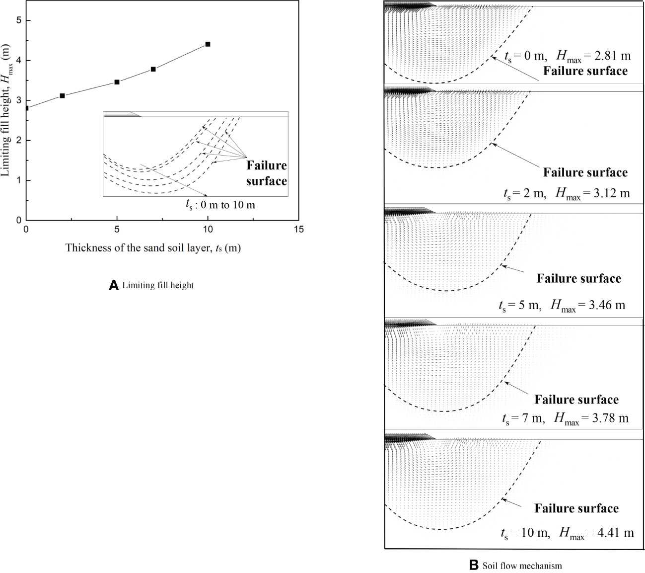
Figure 4 Effect of the sand layer thickness in foundation: (A) limiting fill height; (B) soil flow mechanism.
3.2 Effect of dyke width
In order to adapt to the different soil grounds and projects, the width of geotextile mat dykes ranges widely in practice. To further explore the influence of the sandbag width at the base of the dyke – W onto the stability of the large geotextile mat dyke, a group of cases with W = 20 ~ 100 m are conducted, while ts = 5 m, tc = 100 m, E = 20 Mpa, φs = 32°, Cs = 0.1 kPa, Su = 10 kPa, K = 1/2, J = 140 kN/m, as tabulated in Group IV, Table 1.
Figure 5 shows the relationship between the dyke width and the limiting fill height. It can be seen that the limiting fill height, Hmax, decreases with the rise of dyke base width. As W increases, the failure surface extends accordingly. However, the increased bearing capacity of the foundation from enlarged failure surface is not proportional to the rise of associated dyke weight due to wider base. As a result, the limiting fill height of the dyke decreases accordingly. Similar conclusion was also reported by Borges and Cardoso (2002), who found that in terms of overall dyke stability, the embankment geometry, namely the B/H relation (the crest width of embankment), strongly influences the failure type, and the probability of occurring a global failure surface is greater when B/H has a small value. It is therefore concluded that increasing sandbag width at the base of the dyke will leads to adverse effect to the maximum filling height.
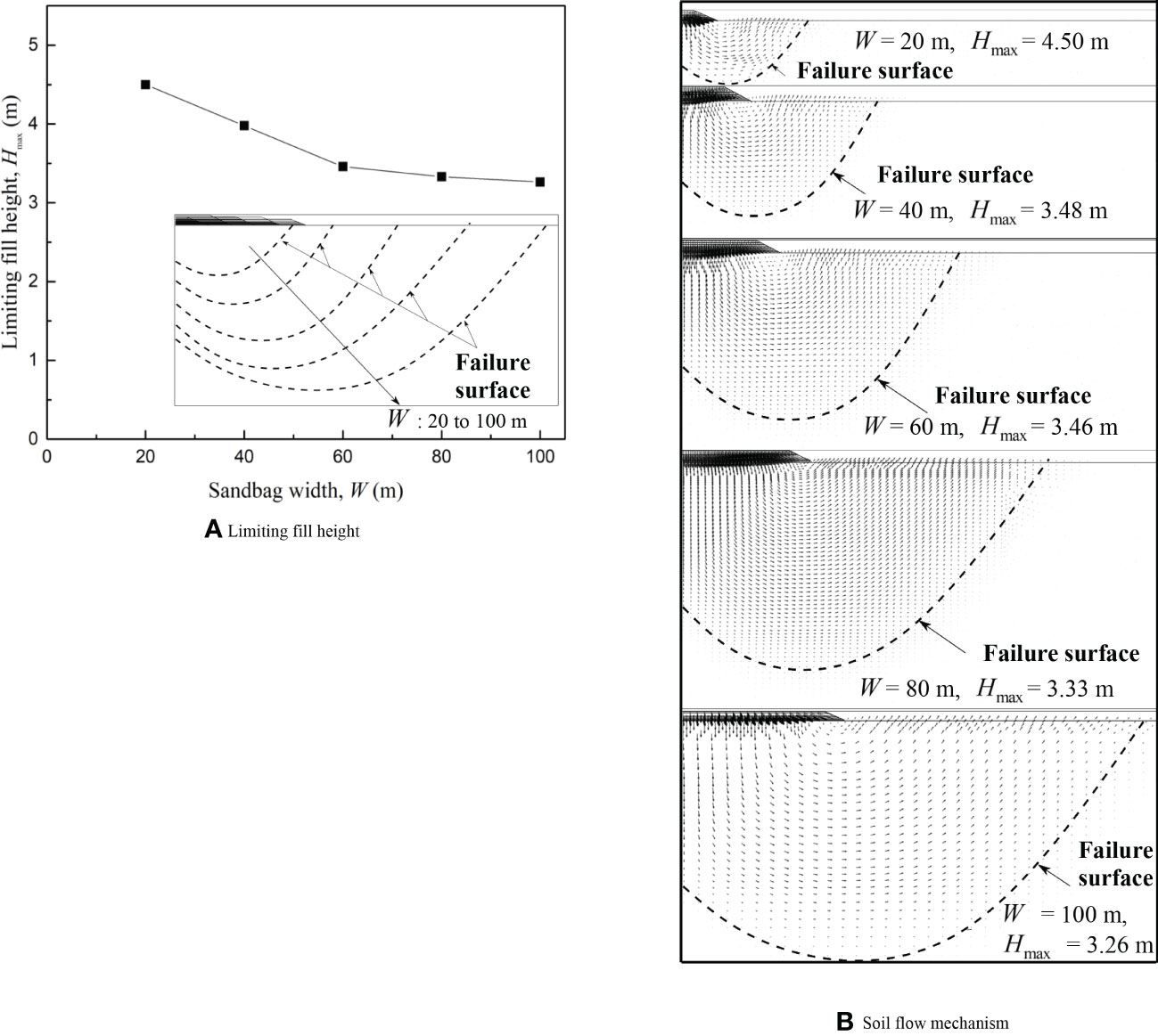
Figure 5 Effect of the width of bottom mat: (A) limiting fill height; (B) soil flow mechanism.
3.3 Effect of shear strength of clay
As demonstrated above, the failure of the dyke is always because of the failure of the soft clay underneath the stiff sand in the foundation, therefore the properties of the soft clay could strongly influence the performance of the dyke. In order to quantify the influence of the clay strength Su on the failure mechanism and the limiting fill height of the dyke with non-uniform geotextile mats, a group of cases with the shear strength of clay layer varying from 5 kPa to 20 kPa are conducted, and the other parameters are kept constant as ts = 5 m, tc = 100 m, E = 20 Mpa, φs = 32°, Cs = 0.1 kPa, K = 1/2, W = 60 m, and J = 140 kN/m (Group V, Table 1). Figure 6A shows the soil flow mechanisms and failure surfaces for various Su. It is clear that the soil failure zone reduces in both width and depth with the undrained shear strength Su increases. Consequently, the limiting fill height of the dyke increases accordingly. In Figure 6B, it is clear that the failure modes of the large geotextile mat dyke with different shear strengths for the underlying clay are almost the same. Therefore, it can be concluded that with the increase of clay strength Su, the failure surface gradually reduces, and the limiting fill height of dykes increases significantly under the same load. Similar finding was also reported by Rowe and Li (2005) who investigated the influence of the soil strength Su on the stability of slopes or the traditional dyke (not geotextile mat) over soft clay.
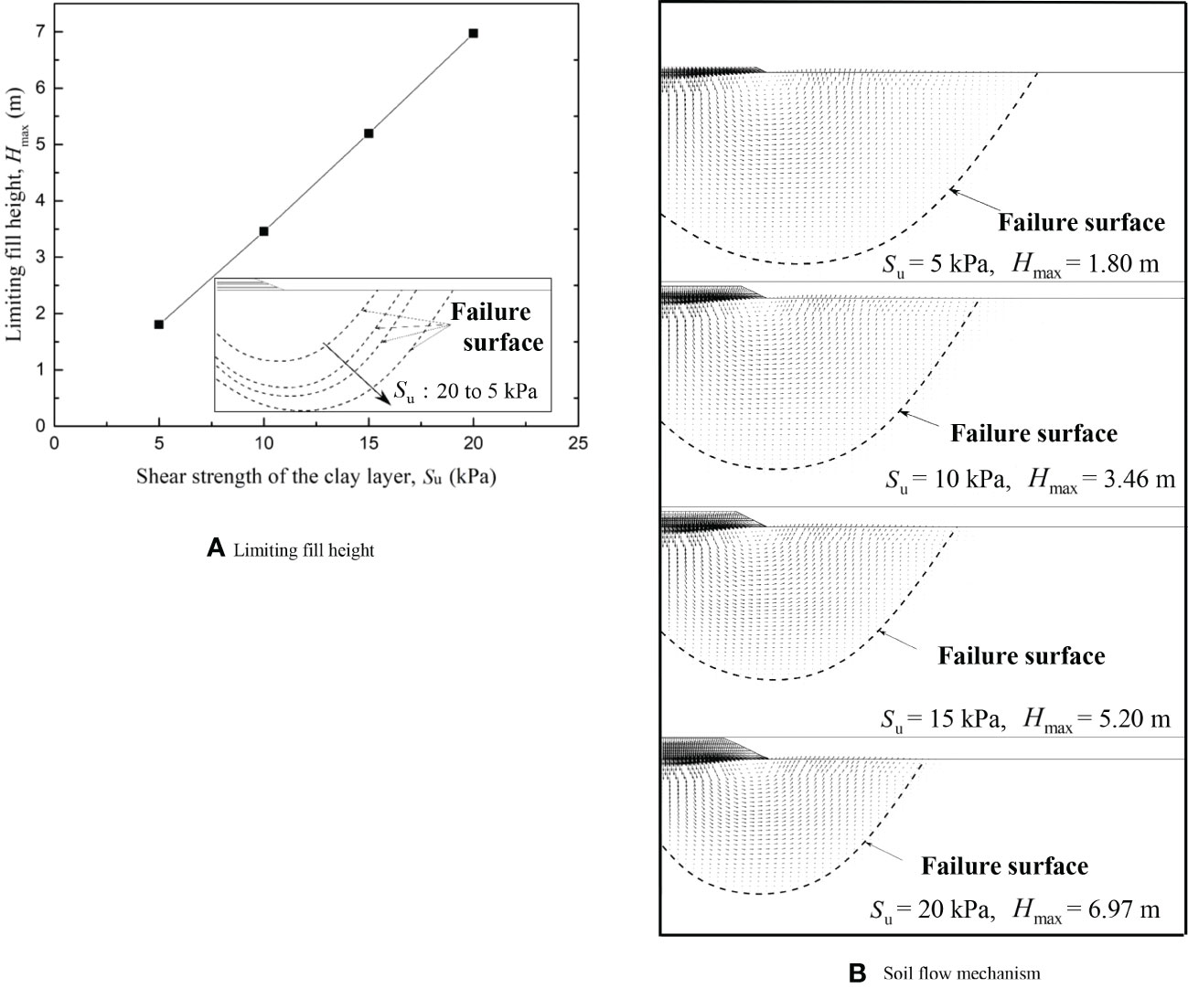
Figure 6 Effect of the undrainded shear strength of the foundation clay: (A) limiting fill height; (B) soil flow mechanism.
3.4 Effect of sand properties
To quantify the influence of the elastic modulus and friction angle of sand layer on the stability of dykes, the limiting fill height of the dykes and instability forms of large geotextile mat dykes, three different elastic modulus and four internal frictions of sand layer are applied. The detailed parameters are shown in Groups VI and VII, Table 1, and the other parameters are set consistent as ts = 5 m, tc = 100 m, Cs = 0.1 kPa, Su = 10 kPa, K = 1/2, W = 60 m, J = 140 kN/m. The results of the effects of sand properties are shown in Figure 7. It can be found the sand properties (E and φs) have a minimal effect on the limiting fill height and failure mechanism of geotextile mat dykes on sand overlying clay.
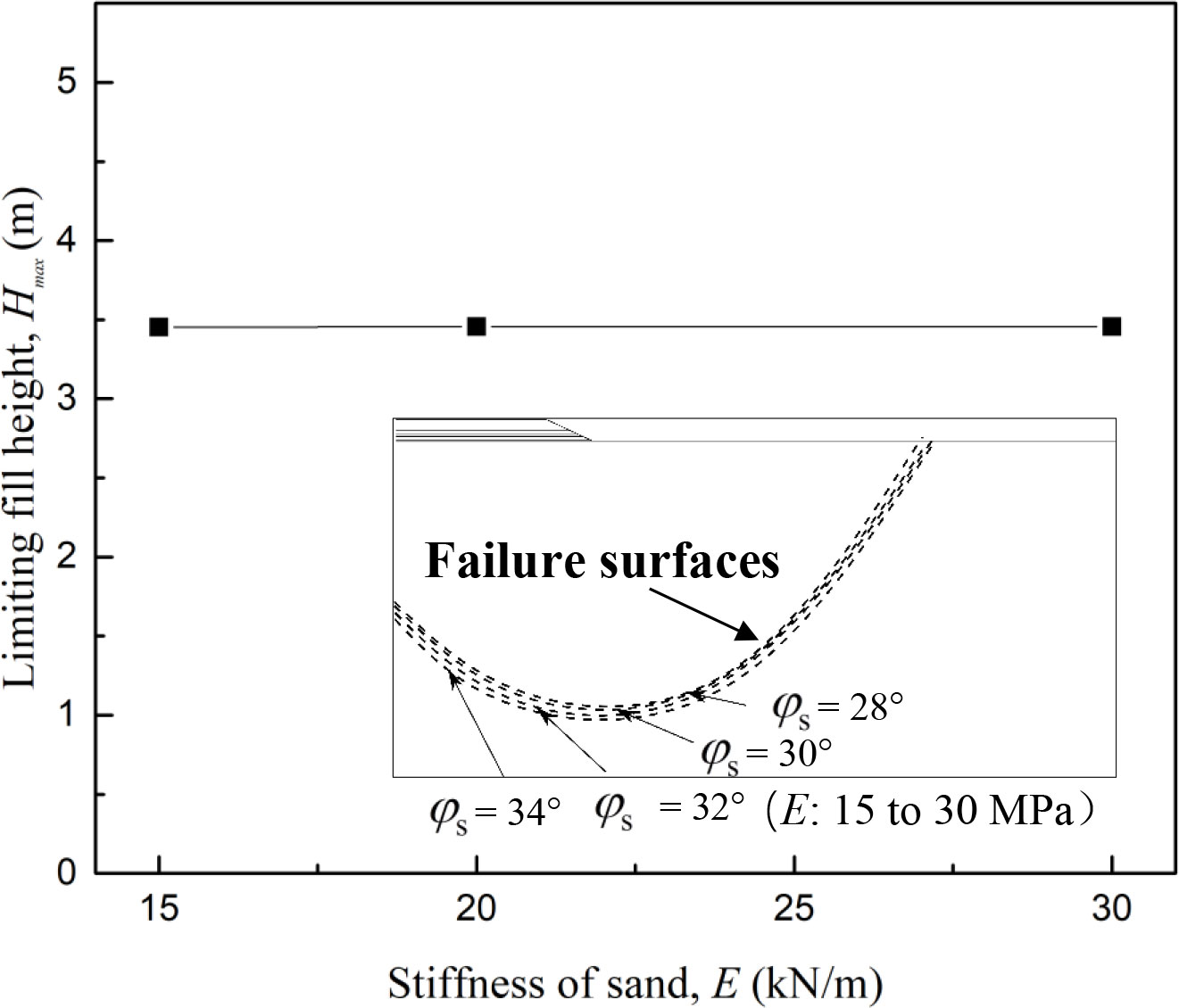
Figure 7 Effect of soil properties of the underlying sand layer in foundation.
3.5 Effect of tensile stiffness of geotextiles
The strength of the geotextiles could potentially influence the overall performance of the dyke. To derive an empirical formulae for engineering design, the effect of the tensile stiffness of geotextiles, J, onto the stability of large geotextile mat dykes, a group of cases with different geotextile tensile stiffness J = 50, 140, 200, 500, 1000, and 2000 kN/m, are modelled, and the other parameters are maintained the same as E = 20 Mpa, φs = 32°, Cs = 0.1 kPa, Su = 10 kPa, W = 60 m, K = 1/2, ts = 5 m, as shown Groups VIII, Table 1. From Figure 8, it can be seen that the tensile stiffness of geotextiles has a minimal effect on the limiting fill height. This is because the sand layer is much stiffer than the geotextiles. The geotextile only needs to bear the tensile force induced by the mat. Simply increase the stiffness of geotextiles is not beneficial to improve the bearing capacity of the foundation.
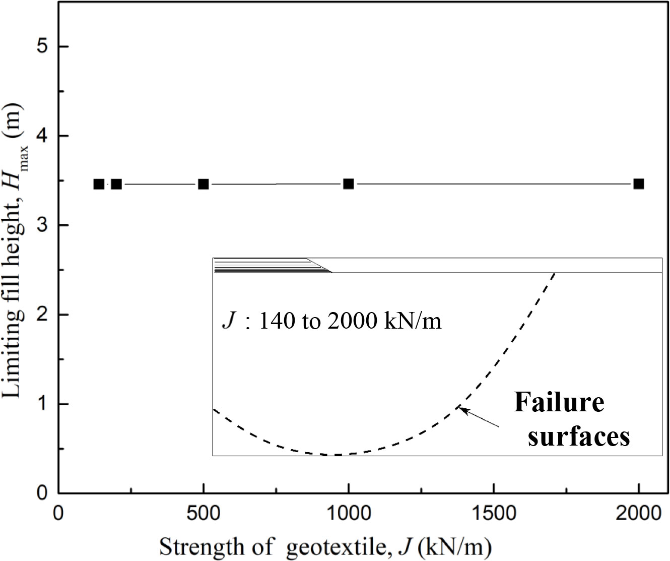
Figure 8 Effect of the strength of geotextile.
3.6 Effect of slope ratio of large geotextile mat dykes
To evaluate the influence of the slope ratio of dykes K on the stability of the dyke, a group of cases with various K = 1/1, 1/2, 1/3 are modelled, while the other parameters are identical as ts = 5 m, tc = 100 m, E = 20 Mpa, φs = 32°, Cs = 0.1 kPa, Su = 10 kPa, W = 60 m, J = 140 kN/m (Group IX, Table 1). From Figure 9 it can be seen that the slope ratio K has a minimal effect on the limiting fill height and failure modes of the geotextile mat dyke on sand-overlying-clay soil deposits.
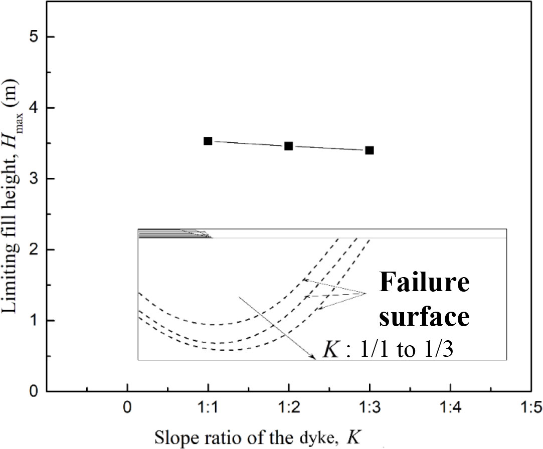
Figure 9 Effect of the slope ratio of larger geotextile mat dyke.
4 Empirical formulae
Through the above parametric study it is found that the sand layer thickness ts, the width of the dyke base W, and the undrainded shear strength of clay layer Su, are the principal influencing factors to the limiting fill height of dyke, while the tensile strength of geotextiles J, the material properties of sand layer E and φs, and the slope ratio of dykes K, have minimal influences on dyke stability, which can be neglected. Based on these numerical results which is summarized in Group X, Table 1, empirical formulas are derived to predict the limiting fill height for dykes and factor of safety for the design purpose.
4.1 Limiting fill height
The corresponding limiting fill height, Hmax, can be analyzed using two non-dimensional parameters: (i) the normalized dyke base width, ts/W, and (ii) the normalized soil strength γsHmax/Su. Regression analysis is conducted, and Figure 10 shows the fitted result which can be expressed as Equation 1 with R2 = 0.95 for the range of W = 20 ~ 100 m.

Figure 10 Design chart of the limiting fill height of mats.
4.2 Stablity
For engineering design of the dyke with non-uniform geotextile mats on sand-overlying-soft clay, the safety factor is a key factor to evaluate the stability of dykes. Following the study of Zhang et al. (2015) where the finite element strength reduction method is used to obtain the safety factor Fs to evaluate the stability of the soil slope and the primary factors affecting the safety are the slope height H, slope angle β, cohesion c and friction angle φ that was consistent with the research of Dawson et al. (1999), the safety factors of the geotextile mat dyke with various fill heights from FE results are shown in Figure 11. Based on the results, an equation can be approximated (with R2 = 0.95) as

Figure 11 Design chart of the factor of safety.
where the safety factor of the dyke can be design in the range of 0< H< Hmax, and the filling height H varies from 2 m to 10 m within practical ranges.
5 Conclusions
This study reports the investigation on the large geotextile reinforced dyke construction on the sand-overlying-clay foundation. A FE model is generated using ABAQUS, which is validated against existing testing results. Parametric study is then conducted to quantify the effect of potential influencing factors. The failure mechanism of the composite foundation and the limiting fill height are investigated by considering various influencing factors within practical ranges:
(1) A unique global failure mode of the dyke on the sand-overlying-clay foundation is observed through numerical study.
(2) For the condition of the sand-overlying-clay foundation, the sand layer thickness ts, the dyke base width W, and the soft clay shear strength Su are the main factors affecting the stability of the large geotextile mat dyke, while the geotextile strength J, the material properties of sand E, φs and dyke slope K have minimal influence on the stability, which can be neglected. To improve the stability of the dyke in the engineering design, the sand layer thickness can be increased, or the width of the dyke base can be decreased, or the shear strength of the soft clay can be strengthened.
(3) Based on parametric study results, an empirical formula for calculating the filling height Hmax of the large geotextile mat dyke is proposed (i.e. Equation 1). Once the limiting fill height is obtained, the factor of safety of the dam can be evaluated against any fill height design (i.e. Equation 2).
Data availability statement
The raw data supporting the conclusions of this article will be made available by the authors, without undue reservation.
Author contributions
SY and MZ contributed to conception and design of the study. WL wrote the first draft of the manuscript. XW performed the statistical analysis. SZ organized the database. SY, MZ, and XZ wrote sections of the manuscript. All authors contributed to the article and approved the submitted version.
Funding
The first four authors gratefully acknowledge the financial support by the National Natural Science Foundation of China (No. 42276213), Special Fund Project of Six Major Marine Industries in 2022 (GDNRC[2022]27), Guangdong Basic and Applied Basic Research Foundation (2021A1515010828& 2020A1515410001), and Guangdong Provincial Key Laboratory of Modern Civil Engineering Technology (2021B1212040003), Key-Area Research and Development Program of Guangdong Province (NO.2020B0101130009), Guangdong Enterprise Key Laboratory for Urban Sensing, Monitoring and Early Warning (No.2020B121202019), and the Fundamental Research Funds for the Central Universities (D2220740& 2022ZYGXZR011).
Conflict of interest
Author XW was employed by the company Guangzhou Construction Engineering Corporation Limited.
The remaining authors declare that the research was conducted in the absence of any commercial or financial relationships that could be construed as a potential conflict of interest.
Publisher’s note
All claims expressed in this article are solely those of the authors and do not necessarily represent those of their affiliated organizations, or those of the publisher, the editors and the reviewers. Any product that may be evaluated in this article, or claim that may be made by its manufacturer, is not guaranteed or endorsed by the publisher.
Abbreviations
H, dike fill height; Hmax, limiting fill height of dyke; h, the thickness of the bottom tube; ts, sand layer thickness; tc, clay layer thickness; E, elastic modulus of Sand; Cs, cohesion of sand; Su, shear strength of clay in undrain condition; φs, internal friction angle of sand; W, width of sandbag; J, tensile stiffness of geotextile; K, slope ratio of big sandbag dyke; γ, unit weight of sand fill; ν, Poisson ratio; C, cohesion; φ, friction angle; ψ, dilation angle; β, slope angle; αs, frictional coefficient of the interface between the infill sand and geotextiles; αg, frictional coefficient of the interface between the layers of large geotextile mats (i.e. geotextile to geotextile; αc, frictional coefficient of the interface between geotextiles and foundation soil; R2, coefficient of determination, the ratio of SSR (sum of squares for regression) over SST (sum of squares for total), i.e. R2=SSR/SST.
References
Anubhav S., Basudhar P. K. (2010). Modeling of soil-woven geotextile interface behavior from direct shear test results. Geotextiles Geomembranes 28 (4), 403–408. doi: 10.1016/j.geotexmem.2009.12.005
Arulrajah A., Bo M. W., Chu J. (2009). Reclamation of a slurry pond in Singapore. Geotechnical Eng. 162 (1), 13–20. doi: 10.1680/geng.2009.162.1.13
Borges J. L., Cardoso A. S. (2002). Overall stability of geosynthetics-reinforced embankment on soft soil. Geotextiles Geomembranes 20 (6), 395–421. doi: 10.1016/S0266-1144(02)00014-6
Chu J., Guo W., Yan S. W. (2011). Geosynthetic tubes and geosynthetic mats: Analyses and applications. Geotechnical Eng. 42 (1), 57.
Dawson E. M., Roth W. H., Drescher A. (1999). Slope stability analysis by strength reduction. Geotechnique 49 (6), 835–840. doi: 10.1680/geot.1999.49.6.835
Guo W., Chu J., Yan S. (2015). Simplified analytical solution for geosynthetic tube resting on deformable foundation soil. Geotextiles Geomembranes 43 (5), 432–439. doi: 10.1016/j.geotexmem.2015.04.017
Guo W., Chu J., Yan S., Nie W. (2013). Geosynthetic mattress: Analytical solution and verification. Geotextiles Geomembranes 37, 74–80. doi: 10.1016/j.geotexmem.2013.02.001
Kenny M. J., Andrawes K. Z. (1997). The bearing capacity of footings on a sand layer overlying soft clay. Geotechnique 47 (2), 339–345. doi: 10.1680/geot.1997.47.2.339
Lawson C. R. (2008). Geotextile containment for hydraulic and environmental engineering. Geosynthetics Int. 15 (6), 384–427. doi: 10.1680/gein.2008.15.6.384
Liu A. M., Yan S. W. (2012). New construction method of marine cofferdam on the soft ground in tideland. Adv. Mat. Res. 446-449, 1785–1790. doi: 10.4028/www.scientific.net/AMR.446-449.1785
Malik J., Sysala S. (2011). Analysis of geosynthetic tubes filled with several liquids with different densities. Geotextiles Geomembranes 29 (3), 249–256. doi: 10.1016/j.geotexmem.2010.11.004
Morán R., Toledo M.Á. (2011). Research into protection of rockfill dams from overtopping using rockfill downstream toes. Can. J. Civil Eng. 38 (12), 1314–1326. doi: 10.1139/l11-091
Orendorff B., Al-Riffai M., Nistor I., Rennie C. D. (2013). Breach outflow characteristics of non-cohesive embankment dams subject to blast. Can. J. Civil Eng. 40 (3), 243–253. doi: 10.1139/cjce-2012-0303
Peng W., Chen L., Zhou X. (2018). “Application of Large-size sandbag cofferdam in land reclamation engineering,” in Paper presented at the GeoShanghai International Conference.
Rowe R. K., Li A. L. (2005). “Geosynthetic-reinforced embankments over soft foundations”. Geosynthetics Int. 12 (1), 50–85. doi: 10.1680/gein.2005.12.1.50
Shin E. C., Oh Y. I. (2004). Consolidation process of geotextile tube filled with fine-grained materials. Int. J. Offshore Polar Engineer Vol. 14 No. 02 pp, 150–158.
Teh K. L., Cassidy M. J., Leung C. F., Chow Y. K., Randolph M. F., Quah C. K. (2008). Revealing the bearing capacity mechanisms of a penetrating spudcan through sand overlying clay. Géotechnique 58 (10), 793–804. doi: 10.1680/geot.2008.58.10.793
Tian Y., Wang D., Cassidy M. (2011). “Large Deformation finite element analysis of offshore geotechnical penetration tests,” in Paper presented at the 2nd International Symposium on Computational Geomechanics.
Wang H., Feng S., Shen Y., Chang J. (2022). Experimental investigation on the shear characteristics and failure mechanism between Geomembrane/Geotextile interfaces. J. Testing Eval. 50 (4), 2083–2102. doi: 10.1520/JTE20210790
Wang L., Zhang G., Zhang J. (2011). Centrifuge model tests of geotextile-reinforced soil embankments during an earthquake. Geotextiles Geomembranes 29 (3), 222–232. doi: 10.1016/j.geotexmem.2010.11.002
Wei X., Wang J., Ding Z. (2013). Displacement analysis of geomembrane bag with sand soil cofferdam in zhoushan undersea immersed tube tunnel. Chin. J. Rock Mechanics Eng. 32 (9), 1835–1842. doi: 10.3969/j.issn.1000-6915.2013.09.015
Yan S. W., Chu J. (2010). Construction of an offshore dike using sllury filled geotextile mats. Geotextiles Geomembranes. 28, 422–433. doi: 10.1016/j.geotexmem.2009.12.004
Yan S. W., Chu J., Fan Q. J., Yan Y. (2009). “Building a breakwater with prefabricated caissons on soft clay,” in Proceedings of the Institution of Civil Engineers-Geotechnical Engineering, Vol. 162. 3–12.
Zhang N., Shen S., Wu H., Chai J., Xu Y., Yin Z. (2015). Evaluation of effect of basal geotextile reinforcement under embankment loading on soft marine deposits. Geotextiles Geomembranes 43 (6), 506–514. doi: 10.1016/j.geotexmem.2015.05.005
Zheng G., Zhou H., Cheng X., Liu J., Zheng S. (2016). Numerical research on ultimate bearing capacity of sand-clay bilayer foundation. Rock Soil Mechanics 37 (5), 1475–1487.
Zhou M., Hossain M. S., Hu Y., Liu H. (2013). Behaviour of ball penetrometer in uniform single-and double-layer clays. Géotechnique 63 (8), 682–694. doi: 10.1680/geot.12.P.026
Keywords: geotextile reinforced dyke, layered clay, stability, failure mechanism, safety factor (FS)
Citation: Yang S, Liao W, Wang X, Zhou M, Zhang X and Zhuang S (2023) Behavior of the geotextile reinforced dykes on sand-overlying-clay deposit. Front. Mar. Sci. 10:1070900. doi: 10.3389/fmars.2023.1070900
Received: 19 October 2022; Accepted: 10 January 2023;
Published: 31 January 2023.
Edited by:
Grzegorz Różyński, Polish Academy of Sciences, PolandReviewed by:
Marek Kulczykowski, Institute of Hydroengineering Polish Academy of Sciences, PolandFangwei Yu, Institute of Mountain Hazards and Environment, Chinese Academy of Sciences (CAS), China
Chong Jiang, Central South University, China
Copyright © 2023 Yang, Liao, Wang, Zhou, Zhang and Zhuang. This is an open-access article distributed under the terms of the Creative Commons Attribution License (CC BY). The use, distribution or reproduction in other forums is permitted, provided the original author(s) and the copyright owner(s) are credited and that the original publication in this journal is cited, in accordance with accepted academic practice. No use, distribution or reproduction is permitted which does not comply with these terms.
*Correspondence: Mi Zhou, emhvdW1pQHNjdXQuZWR1LmNu