 Bin Wang1,2
 Dongdong Han
 Wenhua Wang
 Xin Li
- 1Key Laboratory of Far-shore Wind Power Technology of Zhejiang Province, Hangzhou, China
- 2Powerchina Huadong Engineering Corporation Limited, Hangzhou, China
- 3State Key Laboratory of Coastal and Offshore Engineering, Dalian University of Technology, Dalian, China
- 4Institute of Earthquake Engineering, Faculty of Infrastructure Engineering, Dalian University of Technology, Dalian, China
- 5Chinese-German Institute of Engineering, Zhejiang University of Science and Technology, Hangzhou, China
Significant structural responses pose potential hazards to the safe operation of floating offshore wind turbines (FOWTs). To effectively mitigate the motion of FOWTs using conventional passive vibration control methods such as tuned mass damper (TMD) and multiple tuned mass damper (MTMD), an optimization method for TMD and MTMD in a barge-type FOWT is proposed in this study. A simplified dynamic model of a barge FOWT with MTMD, which includes the tower first bending and floating platform degrees of freedom (DOFs), in addition to the simplified DOF of the MTMD, is derived. The corresponding fully coupled numerical model is established using the updated simulation tool FAST-SC. Subsequently, the unknown parameters and accuracy of the simplified dynamic model are validated via comparison with the results of the coupled numerical model. Moreover, an optimization method is proposed based on the simplified dynamic model considering the prominent coupling effects of FOWT and computational expense, and the GA algorithm is used for TMD and MTMD optimization. Furthermore, the effectiveness of the optimized TMDs and MTMD is evaluated based on the reduction in the coupled responses of the barge FOWT under the selected environmental conditions. Compared with the optimized TMD in the nacelle, the optimized TMD in the platform and MTMD are proven to be more feasible for vibration mitigation under complex environmental loads. Moreover, an improved steady output is obtained using the optimized vibration control methods, in addition to the excellent mitigation effects on structural responses.
1 Introduction
As a type of renewable energy source with extremely promising exploitation prospects, offshore wind energy has developed rapidly in recent years (Willis et al., 2018); the increased installed global capacity reached 21.1 GW in 2021, and it will most likely exceed 550 GW in the next five years, as predicted by the Global Wind Energy Council (Lee and Zhao, 2022). Compared with onshore wind energy, offshore wind energy offers advantages such as higher and steadier inflow winds, less noise pollution, and lower utilization of land resources (Balog et al., 2016). Generally, bottom-fixed foundations of monopile, multi-piles, and jackets are applied in offshore wind farms constructed at water depths less than 50.0 m (Manzano-Agugliaro et al., 2020). From an economic perspective, floating foundations should be selected beforehand when the water depth exceeds 50.0 m (Snyder and Kaiser, 2009). Compared with bottom-fixed foundations, floating foundations are affected by greater environmental loads, and complicated dynamic responses have become the primary bottleneck limiting the development and application of floating offshore wind turbines (FOWTs) (Butterfield et al., 2007). Therefore, effective suppression of the structural vibrations of FOWT under random wind and wave loads is a key challenge in the development of floating offshore wind farms.
Existing approaches for the load mitigation of FOWTs can be categorized into active mechanical control and passive structural vibration reduction methods. In relation to the former approach, Larsen (Larsen and Hanson, 2007) suggested that the first natural frequency of the local pitch controller must be less than the fundamental frequency of the related OWT support system to alleviate the negative damping effects of the pitch controller on FOWT motions. An improved collective pitch control strategy (CPC) comprising a tower-top feedback loop, active pitch-to-stall regulation, and detuned controller gains was proposed by Jonkman (2008), and the improved structural responses of a barge FOWT were examined. Furthermore, increased blade root fatigue loads and fluctuating output also represent important problems. As a prominent characteristic of FOWTs, substantial asymmetric aerodynamic loads impair the control effects of the servo system and the stability of the integrated structure (Njiri and Soeffker, 2016); therefore, Namik (Namik and Stol, 2011) and Mohammadi (Mohammadi et al., 2018) developed an independent pitch control strategy (IPC) to compensate for such deficiencies. The coupling effects between the environmental loads, blade pitch control system and FOWT structural motions have been proven in the studies of Bredmoseh (Bredmose et al., 2017) and Goupee (Goupee et al., 2017); therefore, a multi-signal input and output system for blade pitch control regulations in FOWTs was recommended by Racch (Raach et al., 2014) and Wakui (Wakui et al., 2017) to balance the steady generator output and floating support system motions. Although various improved mechanical control strategies have been proposed to enhance the performance of FOWTs, the increased fatigue loads of rotor blades and the use of mechanical controllers, particularly for more complicated mechanical systems, have not been adequately investigated. Moreover, the positive effects of mechanical systems are limited under extreme winds and waves because such cases are beyond the regulation capacities of FOWT servo systems. Therefore, additional passive structural vibration control methods are applied to mitigate the FOWT responses under complex environmental conditions.
Murtagh et al. (Murtagh et al., 2008) applied a tuned mass damper (TMD) installed on the tower top of a wind turbine and investigated the effect on vibration mitigation. Colwell et al. (Colwell and Basu, 2009) implemented a tuned liquid column damper (TLCD) in the fixed-bottom OWT, Zhang (Zhang et al., 2014) Chen (Chen and Georgakis, 2013), and Li (Li et al., 2012) et al. applied a ball vibration absorber to a fixed-bottom OWT to control the structural response under loads such as seismic, wind and waves, it can be concluded that a ball vibration absorber could significantly reduce the structural response of OWT under the above loads. Chen (Chen et al., 2015) and Buckley (Buckley et al., 2018) applied the TLCD to the simplified OWT experiment and numerical model by experimental and numerical methods respectively and discussed the applicability of TLCD.
In the aforementioned studies, the parameters of TMD and TLCD were determined using the proposed empirical formulas in civil engineering, and the coupling effects of OWTs were neglected in the structural vibration control method design. The interactions among the environmental loads, rotor nacelle assembly (RNA), and support systems are significant for OWTs, particularly for FOWTs. Hence, the influence of such coupling effects on the vibration control method design requires further examination. If fully coupled analysis models are directly applied to the design, the computational expense will be prohibitively high. Therefore, to coordinate the simulation accuracy and efficiency, Stewart et al. (Stewart, 2012; Stewart and Lackner, 2013) established a 3-DOFs simplified dynamic model for a different type of FOWTs based on the Lagrange equation for optimizing the TMD parameters by surface plot method and genetic algorithm. Based on the same approach, He et al. [25 and Yang (Yang et al., 2019) studied the vibration suppression effect of barge-type with optimized single nacelle TMD and single platform TMD, respectively. Si et al. (Si et al., 2014a; Si et al., 2014b) established a 5-DOFs simplified dynamic model to simulate the spar-type FOWT with a TMD installed in the nacelle or platform respectively based on the D’Alembert’s principle, the TMD parameters were optimized by empirical formulas, surface plot and genetic algorithm. Li et al. (2017) established a 4-DOFs simplified dynamic model to simulate the semi-submersible FOWT with a TMD installed in the nacelle based on the D’Alembert’s principle, and the surface plot and genetic algorithm were used to optimize the TMD parameter. – modeled a multi-body dynamic model of spar-type FOWT by SIMPACK and an improved artificial fish swarm algorithm was used for TMD parameters optimization. Park et al. (2020) added a TLCD control program based on FAST v8 and investigated multi-objective optimization for the TLP FOWT with orthogonal TLCDs based on the developed program.
However, these researches on vibration mitigation of FOWT have studied the effect of TMD installed in either the nacelle or the platform of FOWTs, which didn’t consider the case that the TMD installed in the nacelle and platform simultaneously. Jin et al. (2018) considered the effect of TMDs simultaneously in the nacelle and platform of barge-type FOWT by SIMPACK, a 5-DOF simplified dynamic model for TMDs parameters optimization was established, however, according to the reference (Namik and Stol, 2011), the surge motion almost has no impact on the dynamic response for the barge-type FOWT, therefore, a more reasonable simplified model should be established to simplify the TMD parameters optimization. Yang (Yang and He, 2020) established an aero-hydro-servo-structure-TMDs couple kinetics model to consider the effect of TMDs simultaneously in the nacelle and platform of spar-type FOWT, but the hydrodynamic loads are calculated by the Morrison equation, which makes the model unsuitable for barge-type FOWT. Therefore, the more accurate and direct approach is to modify the simulator tool FAST-SC so that it can simulate the TMD installed in the nacelle and the platform simultaneously in time domain simulation, and a more reasonable simplified model should be established for TMDs parameters optimization of barge-type FOWT.
The main contributions of this paper compared with the existing results are summarized as:
1. The simulation tool FAST-SC is developed to be capable of simultaneously accounting for nacelle TMD and platform TMD in fully coupled analysis.
2. The simplified dynamic model is derived and established using the Lagrange equation to optimize TMD parameters for nacelle TMD and platform TMD.
3. Mitigation effects of the optimized TMDs are evaluated based on the reduced dynamic responses of the barge FOWT under the typical winds and waves.
These observations suggest that the FOWT coupling effects should be considered in the vibration control method design to guarantee the applicability of the proposed vibration control method. To reduce the computational cost, a simplified coupled numerical model of FOWT is proposed for design optimization, and the identified master DOFs are sensitive to the type of floating platform. Moreover, owing to its significant influence on the optimized parameters, the master DOFs of the simplified model should be carefully selected. The optimization models for TMD in typical FOWTs have been established in previous studies, whereas models for the multiple tuned mass damper (MTMD) require further investigation. To address this deficiency, a simplified coupled model of a barge FOWT with MTMD is established in this study, and an artificial intelligence-based algorithm is employed in the MTMD optimization. The remainder of this paper is organized as follows. The basic parameters and dynamic characteristics of the barge FOWT are introduced in Section 2, and the derivations of the simplified coupled model of the barge FOWT with MTMD based on multibody dynamics theory are systematically illustrated in Section 3. The updated simulation tool, FAST-SC, is also discussed in this section. The estimation and evaluation of unknown parameters and simulation accuracy of the simplified coupled model via comparison with the fully coupled model in the updated FAST-SC are discussed in the subsequent section. Furthermore, using a genetic algorithm (GA), the optimization of TMDs and MTMDs in the barge FOWT performed based on the simplified coupled model is described in Section 5. In Section 6, based on the mitigation effects on the essential structural responses and operation parameters of the fully coupled model, the efficacy of the optimized TMDs and MTMD is evaluated, and the key conclusions and scope for future work are summarized in Section 7.
2 NREL 5MW turbine and barge platform
A three-bladed and upwind NREL 5 MW baseline WT was utilized in the study, and a barge-type floating structure proposed by National Renewable Energy Laboratory (NREL) (Jonkman, 2008) was selected as the supporting platform. A schematic of the barge FOWT is presented in Figure 1, and the related basic parameters are listed in Table 1. More details regarding the NREL-5 MW baseline and barge platform are introduced in (Jonkman, 2008; Jonkman et al., 2009). The natural frequencies of the main DOFs are listed in Table 2 (Jonkman, 2008).
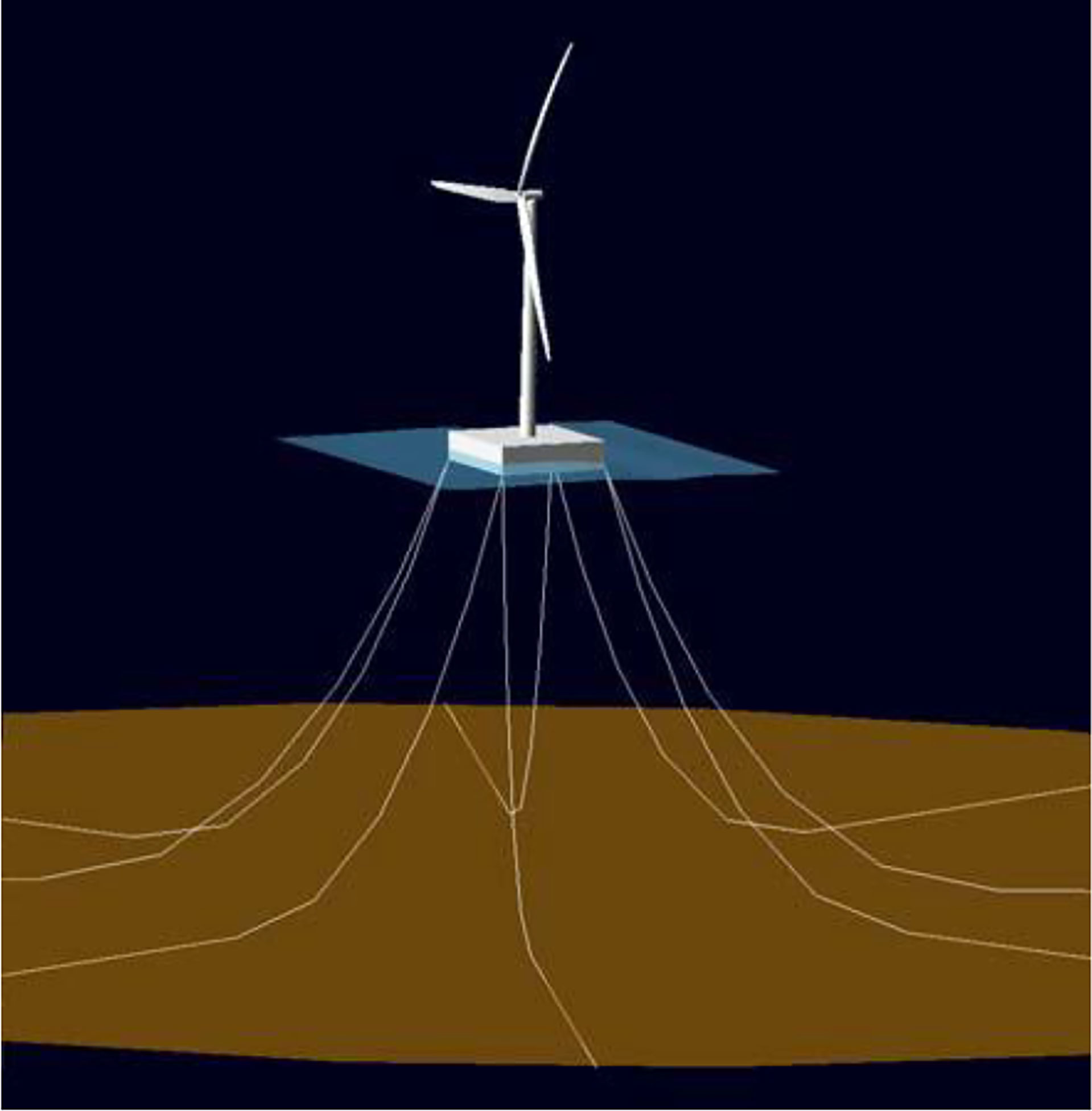
Figure 1 Schematic of the barge FOWT [8].
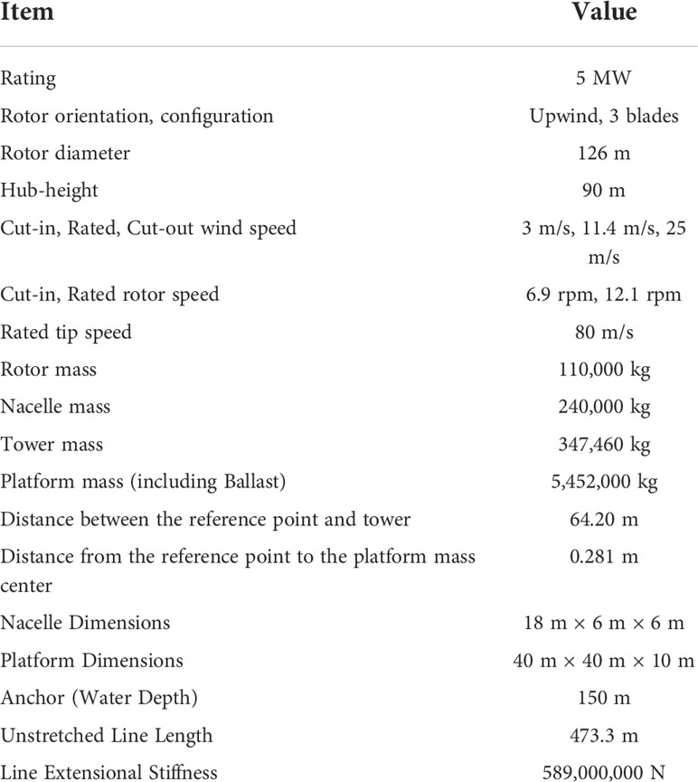
Table 1 Basic parameters of the barge FOWT.
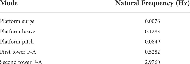
Table 2 Natural frequencies of barge-type FOWT (Jonkman, 2008).
3 Dynamic modeling and simulation tool
3.1 Simplified dynamic model
To alleviate the structural motions of the barge FOWT in the fore-aft (F-A) direction, this study proposes a multiple tuned mass damper (MTMD) configuration, and the nacelle and platform are designated as potential MTMD locations, such as the local TMDs 1 and 2 marked in Figure 2. As introduced in the previous section, in addition to the empirical formulas, the simplified dynamic model with limited DOFs is generalized for application in the design of TMD for FOWTs. Therefore, in this study, a simplified dynamic model of a barge FOWT with an MTMD was established to optimize the MTMD.
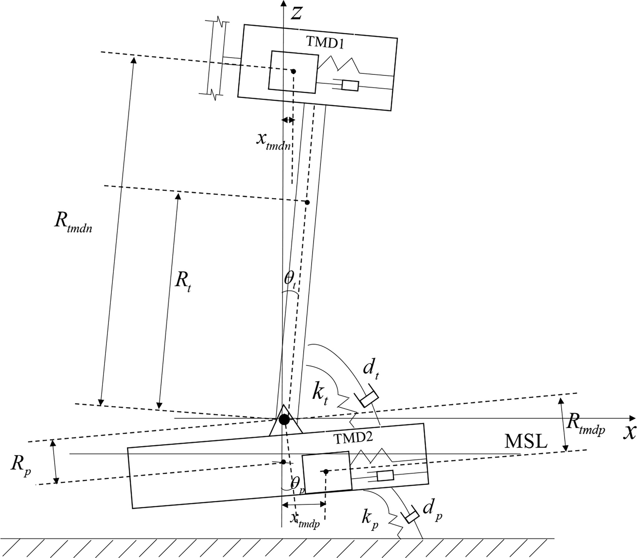
Figure 2 Simplified dynamic model of barge FOWT with MTMD in nacelle and platform.
Based on the remarkable coupling effects between the tower bending and barge platform pitch motions, the tower-first bending mode and floating-platform pitch DOFs are identified as the master DOFs of the barge FOWT. The local damper of the MTMD is simplified as an SDOF with constant stiffness and damping along the designated direction. Hence, the barge FOWT with the MTMD mounted in the nacelle and platform is simplified as an equivalent dynamic system with four DOFs. To derive the governing equation of motion for the simplified dynamic system, the following assumptions were adopted in the derivation.
(1) The barge FOWT is simplified as a multi-body dynamic system, the barge platform, tower, and MTMD are modeled as rigid bodies, and the rotor nacelle assembly is simplified as a lumped mass with respect to the tower top (Stewart and Lackner, 2013). The tower flexibilities were considered by introducing a linear constant hinged bearing at the tower base, as shown in Fig. 2. The spring and damping of the hinged bearing are consistent with those of the tower-first bending mode.
(2) As indicated in the figure, the global coordinate system (X, Y, Z) was defined, and the global X-axis was parallel to the fore-aft direction of the FOWT. The Z-axis was defined along the centerline of the tower and platform, and the positive direction of the global Y-axis was identified using the right-hand rule. The origin of the global coordinate system is located at the interaction between the mean sea level (MSL) and Z-axis.
(3) By neglecting the rotation effects, the local damper is simplified as a single DOF in the designated direction, which consists of a constant mass, spring, and damping elements.
(4) The local dampers mounted in the nacelle and platform comprise an MTMD, and the coordinates of and in the global coordinate system represent the positions of the MTMD local dampers in the nacelle and platform, respectively.
(5) The influence of tower flexibilities and platform pitch DOF is considered in the optimization of the MTMD for barge FOWT using a simplified dynamic model. The effectiveness of the optimized MTMD shall be evaluated in the subsequent fully coupled analysis of the FOWT under winds and waves in the updated FAST-SC.
Based on this assumption, the governing equation of motion for the simplified dynamic system for barge-type FOWT can be derived using the Lagrange equation, which can be expressed in Eq. (1). and the generalized coordinates defined in Eq. (2).
where T and V denote the total kinetic and potential energies of the system, respectively, L indicates the Lagrange operator, and qi symbolizes the generalized coordinate of the system defined in Eq. (2); qi is the generalized velocity of the system; Qi corresponds to the generalized non-potential force of the system; θ signifies the angular displacement with respect to the global Z-axis; x represents the horizontal displacement of the TMD along the global X-axis; and the subscripts t, p, tmdn, and tmdp refer to the tower, platform, and TMD in the nacelle and platform, respectively.
The total kinetic energy T and potential V can be expressed in Eq. (3) and the generalized damping force Qi of the system can be expressed in Eq. (4).
where m indicates the mass of each component of the simplified dynamic system, such as the tower, platform, and TMDs; I indicates the moment of inertia about the mass center of each component, and k symbolizes the equivalent spring stiffness; R indicates the distance between the mass center of each component and the hinged bearing; d denotes the equivalent damping.
Substituting Eqs. (2), (3) and (4) into Eq. (1), Considering the maximum pitch angle of a FOWT does not exceed 10° under the service and ultimate limit states, the small-angle approximation is introduced in this study. e.g., sinθ≈θ and cosθ≈1, thus, the final governing equation of motion for barge-type FOWT with MTMD can be expressed in Eq. (5).
In addition, the allowable strokes of the damper in the nacelle and platform should be constrained because of the limited space in the nacelle and barge platform. According to the dimensions of the barge FOWT listed in Table 1, the allowable stroke ranges of the damper in the nacelle and platform are designated as ± 8 m and ± 18 m, respectively. As defined in Eq. (11), an additional baking force Fstop is applied if the displacement of the local damper reaches the limits of the allowable stroke range.
Here, L indicates the maximum allowable stroke length; Kstop and Dstop denote the designated breaking stiffness and damping, and the related values are 5×10⁵ N/m and 5×10⁵ N·s/m, respectively; and Δx indicates the distance that the TMD traveled beyond the allowable stroke length.
3.2 Description of updated FAST-SC
A fully coupled analysis model of a barge FOWT with an MTMD was established in the updated FAST-SC to evaluate the mitigation effects of the optimized MTMD. The remarkable differences with the simplified dynamic model in Section 3.1 are that the flexibilities of the rotor nacelle assembly (RNA) and floating platform additional DOFs are considered in the fully coupled model, and wind and wave loads are applied. The following theoretical modifications were adopted to establish a fully coupled model in the updated FAST-SC.
For the MTMD mounted in the FOWT, the local dampers in the nacelle and platform can be expressed using Eqs. (8) and (9) based on the coupled analysis theories of FAST.
where and indicate the accelerations of the local damper in the nacelle and platform, respectively; ωn and αn denote the FOWT nodal translational and rotation angular velocities at the nacelle; ωp and αp represent the nodal translational and rotation angular velocities of the floating platform, mtmdn and mtmdp are the mass of the local damper in the nacelle and platform, respectively; Ftmdn and Ftmdp indicate the resultant forces of the local damper in the nacelle and platform, respectively, which can be expressed as
where ktmdn and ktmdp denote the stiffness of the local damper in the nacelle and platform, dtmdn and is the damping of each local damper.
According to the derived governing equations of motion of the MTMD in the FOWT, as expressed in Eqs. (8) – (11), the original TMD module in the FAST-SC is updated, and additional MTMD DOFs are required. Figure 3 shows a schematic of the established fully coupled model of the FOWT with the MTMD in the updated FAST-SC.
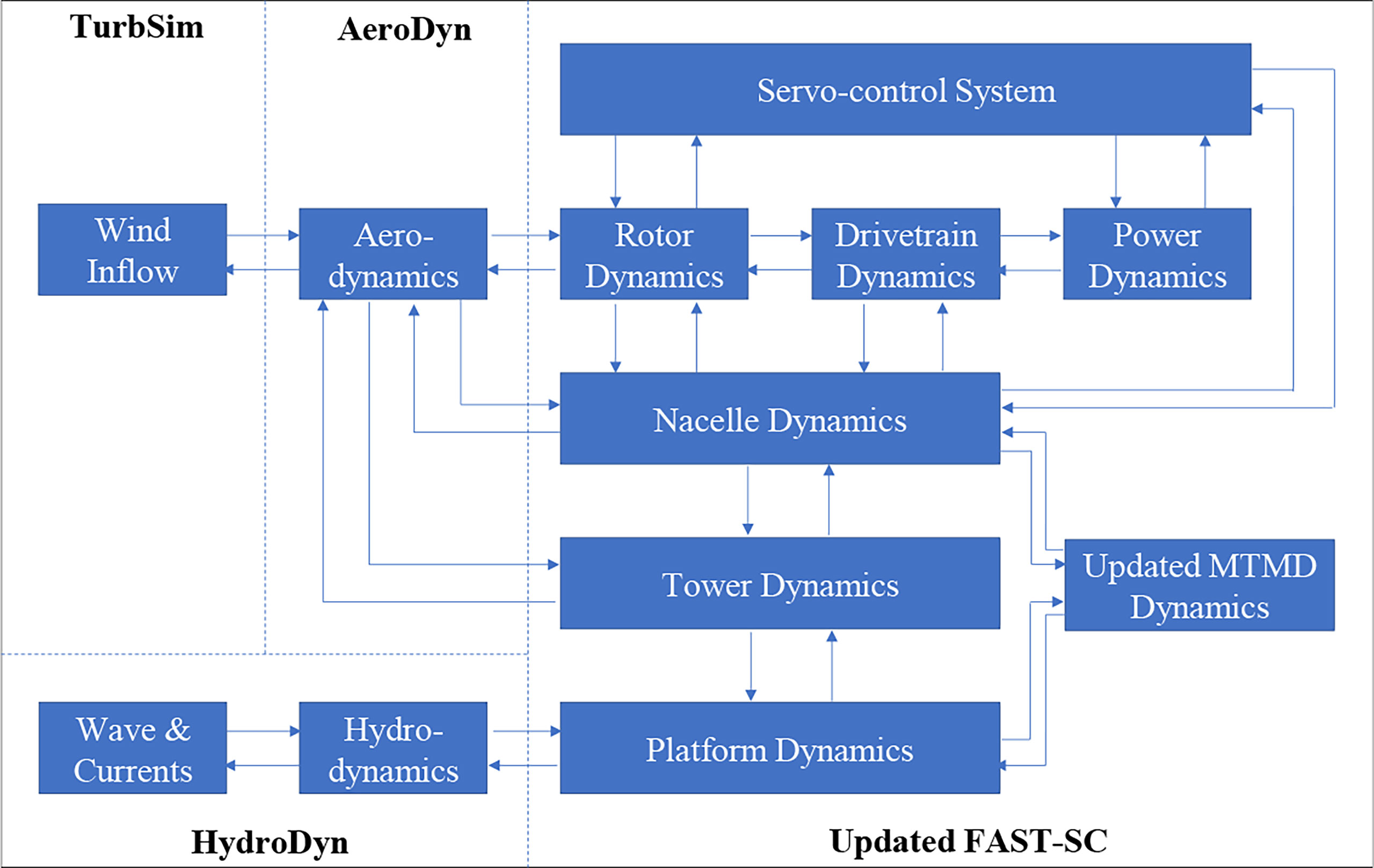
Figure 3 Schematic of the fully coupled model of FOWT with MTMD in the updated FAST-SC.
4 Parameter identification
For the simplified dynamic model in Section 3.1, the mass parameters of mt and mp , and parameters of Rt and Rp can be directly obtained according to the barge OWT parameters listed in Table 1. Meanwhile, the remaining parameters that require further estimation are defined as unknown parameters, such as the equivalent stiffness, damping, and inertia of the tower and platform.
The initial estimated values listed in Table 3 were assigned to identify the unknown parameters, and the Levenberg-Marquardt (LM) algorithm (More, 1978) was applied to minimize the sum of squared errors (SSE) of the structural motions between the derived simplified model and the coupled aero-servo-hydro model in the updated FAST-SC under free decayed pitch motions. The SSE between the outputs of the simplified and coupled models in the updated FAST-SC is defined by Eq. (13).
where m represents the number of outputs, n represents the simulation length, yi(ti) represents the jth output of the updated FAST-SC at the time ti , while fi(ti,P2) represents the jth output of the simplified model with parameter vector P2 at a time ti , Y(ti) and F(ti,P2) represent the related vector notations, and W represents the diagonal weight matrix for normalization.
An initial platform pitch angle of 5° was applied to the simplified and updated model in the FAST-SC. For the latter updated model, only the platform pitching and tower fore-aft bending DOFs were activated to identify unknown parameters in the simplified model. Following several trials and iterations using the LM algorithm, the minimized SSE of the motions between the simplified model and updated model in FAST-SC was obtained, and the remaining unknown parameters were identified, as summarized in Table 3. Meanwhile, using the previous parameter identification method, good agreement is obtained between the free decayed tower and platform motions of the identified simplified and updated coupled model in FAST-SC, as shown in Figure 4.
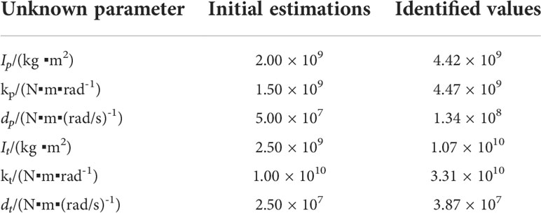
Table 3 Initial estimated and identified values of the unknown parameters.
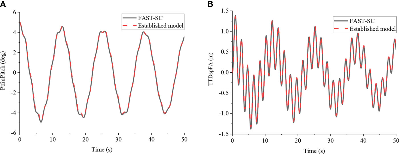
Figure 4 Time domain and frequency domain free decay responses of 5° initial platform pitch angle without TMD obtained using the parameter estimation model and updated FAST-SC model. (A) Platform pitch angle; (B) Tower-top displacement.
Subsequently, the MTMD DOFs in the simplified and updated coupled model in FAST-SC are activated, and an initial pitch angle of 10° is applied to verify the accuracy of the identified unknown parameters. Comparisons between the simplified model and updated coupled model in the FAST-SC of a barge FOWT with MTMD were performed, as shown in Figure 5. As indicated in the figure, the free decayed motions of the simplified model coincided well with the outputs in the updated FAST-SC, even though additional MTMD DOFs were considered. Hence, the simulation accuracy of the simplified dynamic model with the identified unknown parameters is validated and applied in the following optimization of the MTMD for barge FOWTs.
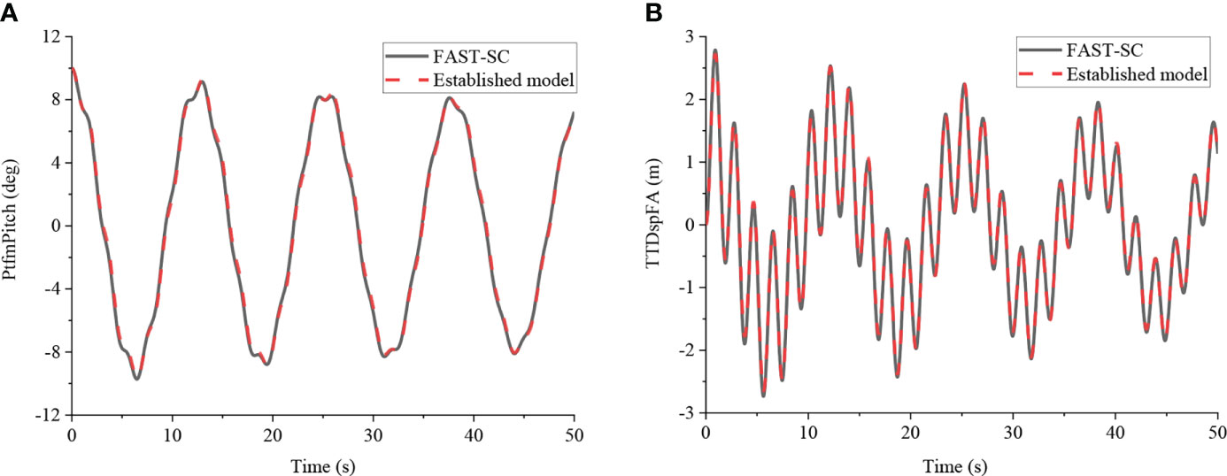
Figure 5 Time domain free decay responses of 10 deg initial platform pitch angle with MTMD between the parameter estimation model and updated FAST-SC model. (A) Platform pitch angle; (B) Tower-top displacement.
5 Optimization of MTMD for FOWT by genetic algorithm
To ensure effective vibration mitigation of a barge FOWT using an MTMD, the essential parameters of MTMD mass, stiffness, and damping should be appropriately designed. Typically, MTMD mass is determined from the perspectives of cost and availability. In this study, the MTMD is assumed to consist of two local TMD mounted on the nacelle and platform. Based on the values recommended by (Stewart, 2012; Stewart and Lackner, 2013; Si et al., 2014b), the mass ratio for each local TMD was designated as approximately 3% with respect to the mass of the upper RNA-tower structure and platform, respectively. Subsequently, according to the barge floating OWT mass parameters listed in Table 1, the mass of local TMD in the nacelle and platform can be obtained, and the values are 20,000 kg and 200,000 kg, respectively. In this work, the location of the nacelle TMD is mounted at the rotor height of the wind turbine. The location of the platform TMD is mounted at the center of mass of the barge-type platform.
For the design of the MTMD stiffness and damping parameters, the global optimization algorithm is an alternative to the empirical formulas proposed by scholars. However, the expensive time costs of using the optimization algorithm should be considered if the complicated coupled numerical model of the floating OWT is directly applied in the optimization. Therefore, it was substituted by the derived simplified model of a barge floating OWT with MTMD in the previous sections to ensure optimization accuracy and computational efficiency in the subsequent study.
In this study, a genetic algorithm (GA) is selected as the global optimization method to optimize the MTMD stiffness and damping parameters. It is an evolution-inspired algorithm that involves the mathematical representations of populations, individual fitness, mutation, and even mating to search for an optimum for a predefined problem. Based on the established simplified dynamic model, an initial 5° platform pitch angle was applied to implement TMD and MTMD parameter optimization, and the STD of the tower top displacement was defined as the fitness function. The probability of the roulette wheel uniform crossover and mutation in the GA are designated as 0.6 and 0.01, respectively. The individual population size was set to 100 and the maximum generation was restricted to 50.
In the GA process, these parameters including nacelle TMD stiffness ( ktmdn ) and damping ( dtmdn ) constants, the platform TMD stiffness ( ktmdp ) and damping ( dtmdp ) constants can be specified in one individual, GA stars by picking a population randomly, when the initial population is created, the first step is to check fitness value, which is defined as the standard deviation of tower top displacement. Next, the algorithm saves the elite and average fitness and goes on to the selection, crossover, and mutation steps. The mutation step helps to maintain genetic diversity in the population, then the process is repeated until the optimal TMD/MTMD parameters are obtained.
The minimum standard deviation of the tower-top displacement in the fore-aft direction can be selected as the objective function:
where T is the simulation time, xttd is the tower-top displacement in the fore-aft direction, is the related mean value.
The boundary conditions can be defined as:
The optimization process of the TMD and MTMD using the derived simplified dynamic model of the barge FOWT is depicted in Figure 6. As indicated in the figure, the minimized STD of the tower top displacement using the optimized TMD in the nacelle (TMD-N) is obtained at the 9th generation, whereas the fitness functions for the optimization of TMD in the platform (TMD-P) and MTMD converge at the 3rd and 6th generations, respectively. Compared with the mitigated STD of tower top displacement using TMDs, more significant reductions are observed using the optimized MTMD, as illustrated in the figure. The optimized TMDs and MTMD are listed in Table 4, and the optimized stiffness and damping of the MTMD are different from those of the related optimized TMDs. For example, the optimized stiffness and damping of the nacelle TMD using the GA based on the simplified model are 6302 and 1598, respectively, while the related optimized values are 7653 and 4013 for the MTMD.
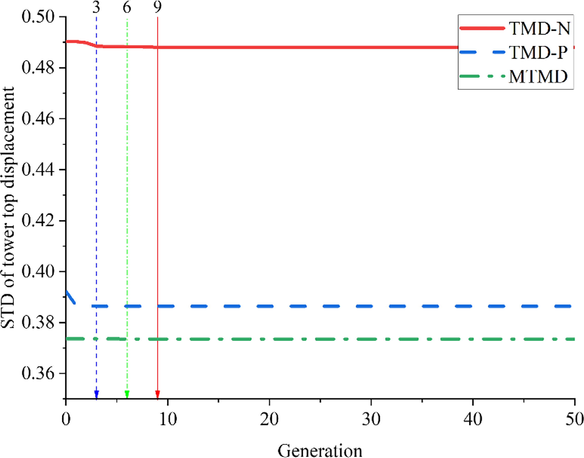
Figure 6 Convergence curves of the fitness function for parameter optimization of different TMD configurations.
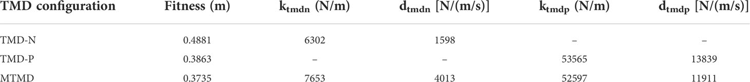
Table 4 TMD parameter optimization results.
The reduced free-decayed tower and platform motions obtained using the optimized TMDs and MTMD are depicted in Figure 7. According to the comparisons of the reduced tower top displacement and platform pitch motion between the nacelle and platform TMDs in Figures 7A, B, the latter is proven to be more feasible. Meanwhile, as indicated in Figures 7C, D, both the nacelle and platform TMDs effectively tuned the pitch frequency of the barge FOWT, indicating that the tuning frequencies of the optimized TMDs were approximately consistent with the pitch frequency of the barge FOWT. Accordingly, it can be inferred that the TMD with the tuned pitch frequency should be mounted on the platform for the barge FOWT compared with the nacelle.
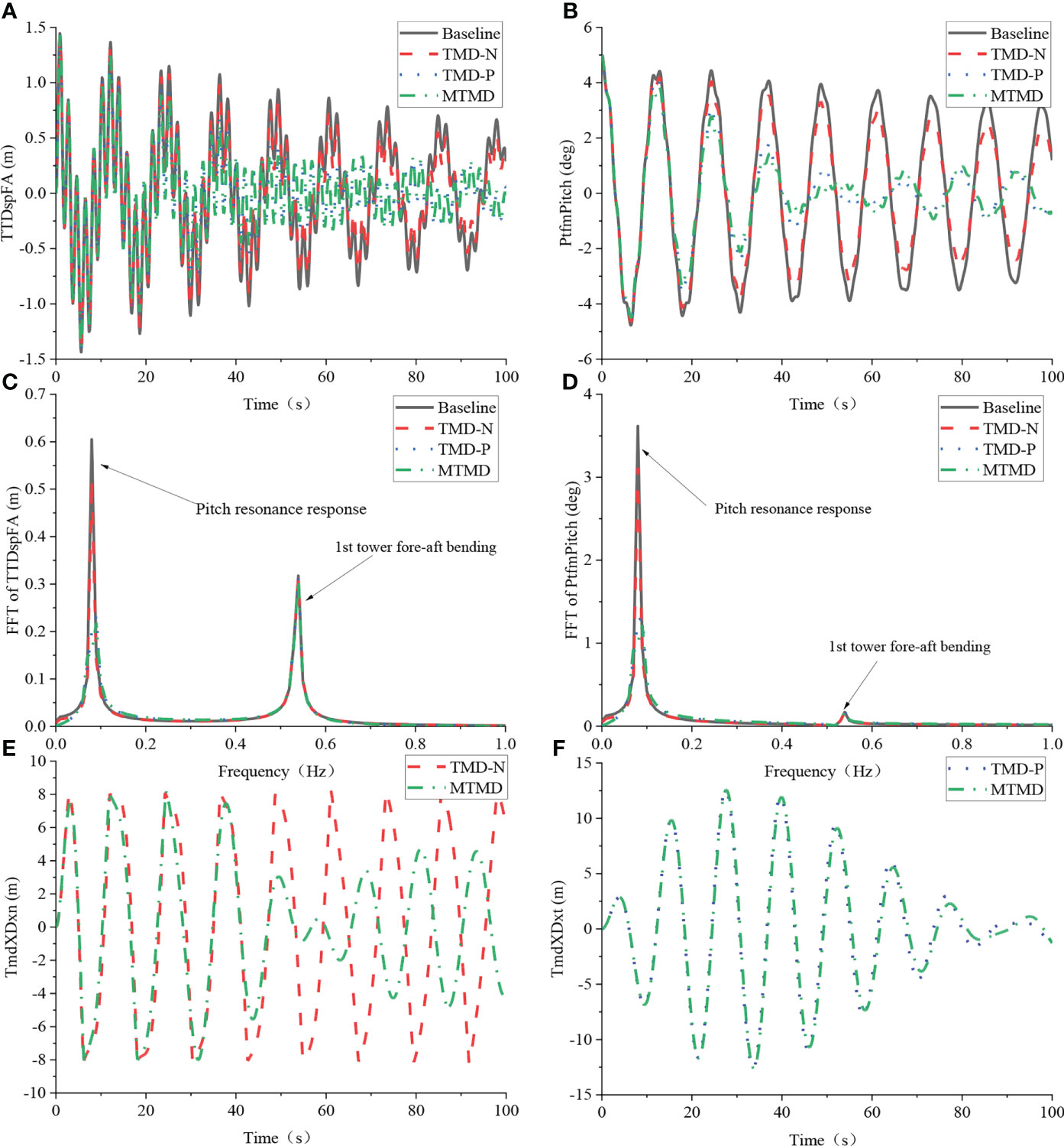
Figure 7 Comparison of free decay response between different optimal TMD configurations. (A) Tower-top displacement; (B) Platform pitch angle; (C) FFT of Tower-top displacement; (D) FFT of Platform pitch angle; (E) TMD stokes of TMD in nacelle; (F) TMD stokes of TMD in platform.
Furthermore, the most effective reduction of the free decayed motions was achieved using the optimized MTMD, as shown in Figures 7A, B. Impressive mitigation in the frequency domain using the MTMD is also observed, and the Fourier amplitudes of the dominant pitch frequency of the tower top displacement and platform pitch motion exhibit a remarkable alleviation. It should also be mentioned that although the first tower bending mode is non-negligible for the tower top displacement, owing to the prominent influence of the platform pitch mode on the tower and platform motions, both the tuning frequencies of the optimized MTMD local nacelle and platform dampers coincide with the dominant platform pitch frequency.
The motions between the optimized TMDs and MTMD were compared, as shown in Figures 7E, F. Owing to the differences in the optimized stiffness and damping between the MTMD and the related TMDs, and the considered coupling effects between the reserved tower, platform, and TMDs DOFs in the simplified dynamic model, the motions of the MTMD are different from those of the related TMDs, especially for the local one in the nacelle.
6 Simulation and analysis
6.1 Load case settings
To evaluate the effectiveness of the optimized TMDs and MTMD using GA based on the simplified dynamic model, a nonlinear fully coupled analysis of a barge FOWT with and without optimized TMDs and MTMD was performed using the updated simulation tool FAST-SC, and the typical load cases were selected according to the offshore standard IEC-61400-3 (IEC [[NoYear]]), as tabulated in Table 5. In addition to the cut-in, rated, and cut-out wind speeds, additional below-rated and over-rated wind speeds are involved. The corresponding wave heights were selected according to the proposed environmental conditions in (He et al., 2017; Yang et al., 2019), and the wave peak period was defined as 12.5 s. The Kaimal spectrum for IEC Class B (Kaimal et al., 1972) was applied to synthesize the three-dimensional (3D) turbulent wind fields in TurbSim (Jonkman, 2009), such as the synthesized 3D turbulent wind field with an average speed of 18 m/s at the hub height as shown in Figure 8. The histories of the irregular wave series were generated using the JONSWAP spectrum in the HydroDyn module in FAST-SC.
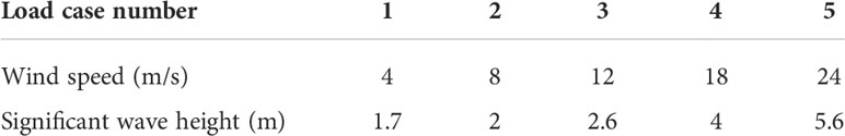
Table 5 Combined wind and wave conditions.
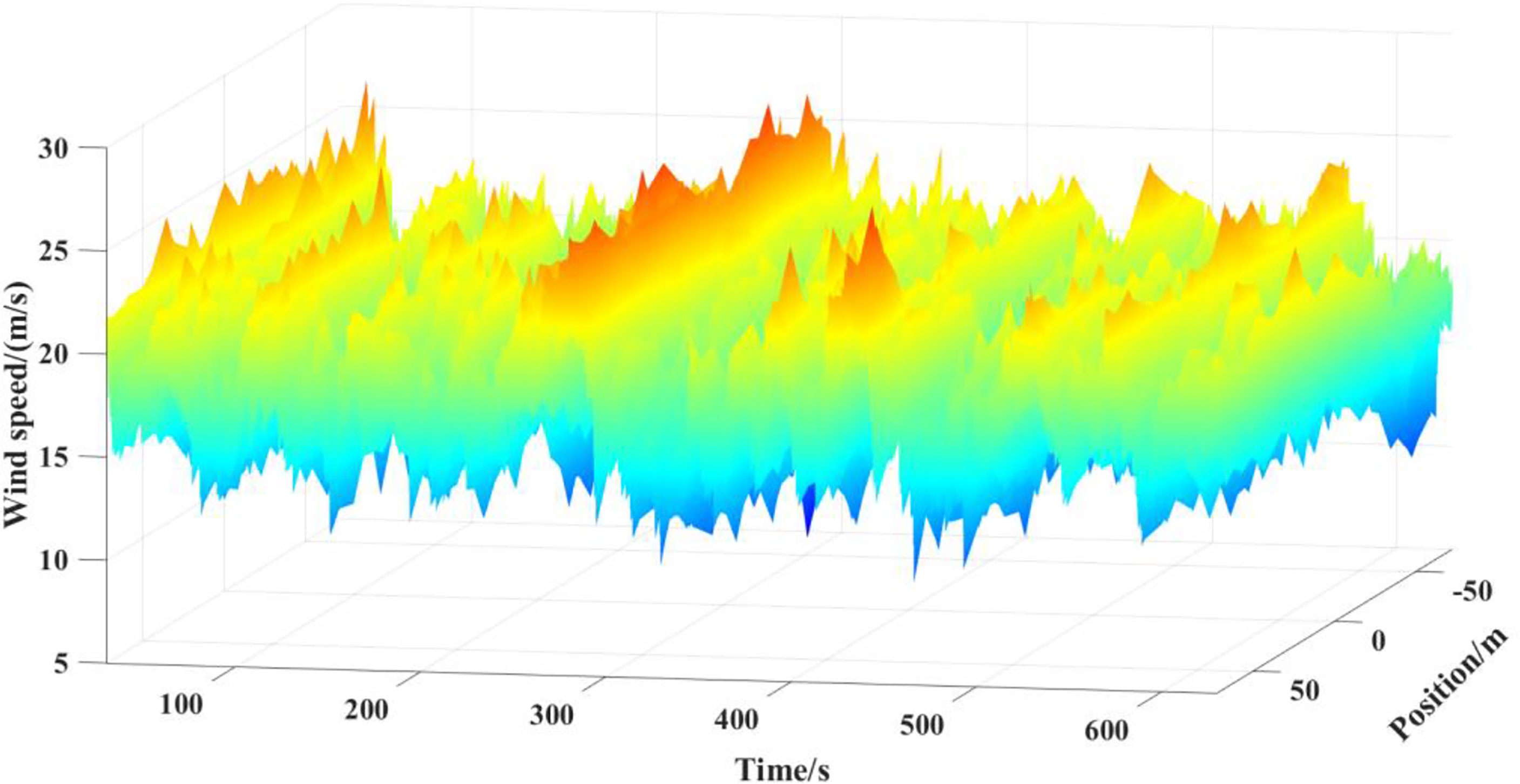
Figure 8 Synthesized three-dimensional turbulent wind field with an average speed of 18 m/s at the hub height.
6.2 Time domain and frequency domain results analysis
In the fully coupled analysis of the barge FOWT under stochastic winds and waves using the updated simulation tool FAST-SC, the simulation length was 630 s, and the initial 30 s were removed in subsequent data processing to eliminate the initial transient effects. The integration step was designated as 0.0125 s to ensure aerodynamic and hydrodynamic simulation accuracy. The related servo control strategies under the selected load cases are deployed using the modified controller by Jonkman (2008) for barge FOWTs, such as the variable speed and blade pitch controller.
To investigate the load reductions of the barge FOWT using the optimized TMDs and MTMD, the following evaluation indicators are defined: the STD of the flapwise bending moment RootMyc at the blade root, the tower base bending moment in the F-A direction TwrBsMyt, and the platform pitch angle PtfmPitch, in addition to the previously selected tower top displacement. The defined suppression rate η in Eq. (15) is applied to quantify the mitigation effects of the optimized TMDs and MTMD. Meanwhile, the root mean square (RMS) and STD of the output power were selected to evaluate the influence of the applied vibration control strategies on the FOWT output under load cases 3 – 5. Moreover, the local TMD displacements between the optimized TMDs and the MTMD were compared.
where σs and σt denote the STDs of the evaluation indices of the barge FOWT with and without passive vibration control strategies, respectively.
Figure 9 illustrates the reduced histories of the barge OWT using the optimized passive vibration control method, where the tower and platform motions are effectively mitigated, particularly using the optimized TMD-P and MTMD, as depicted in Figures 9A–F. Moreover, the positive mitigation effects of the designed TMDs and MTMD on the blade responses are shown in Figures 9G, H.
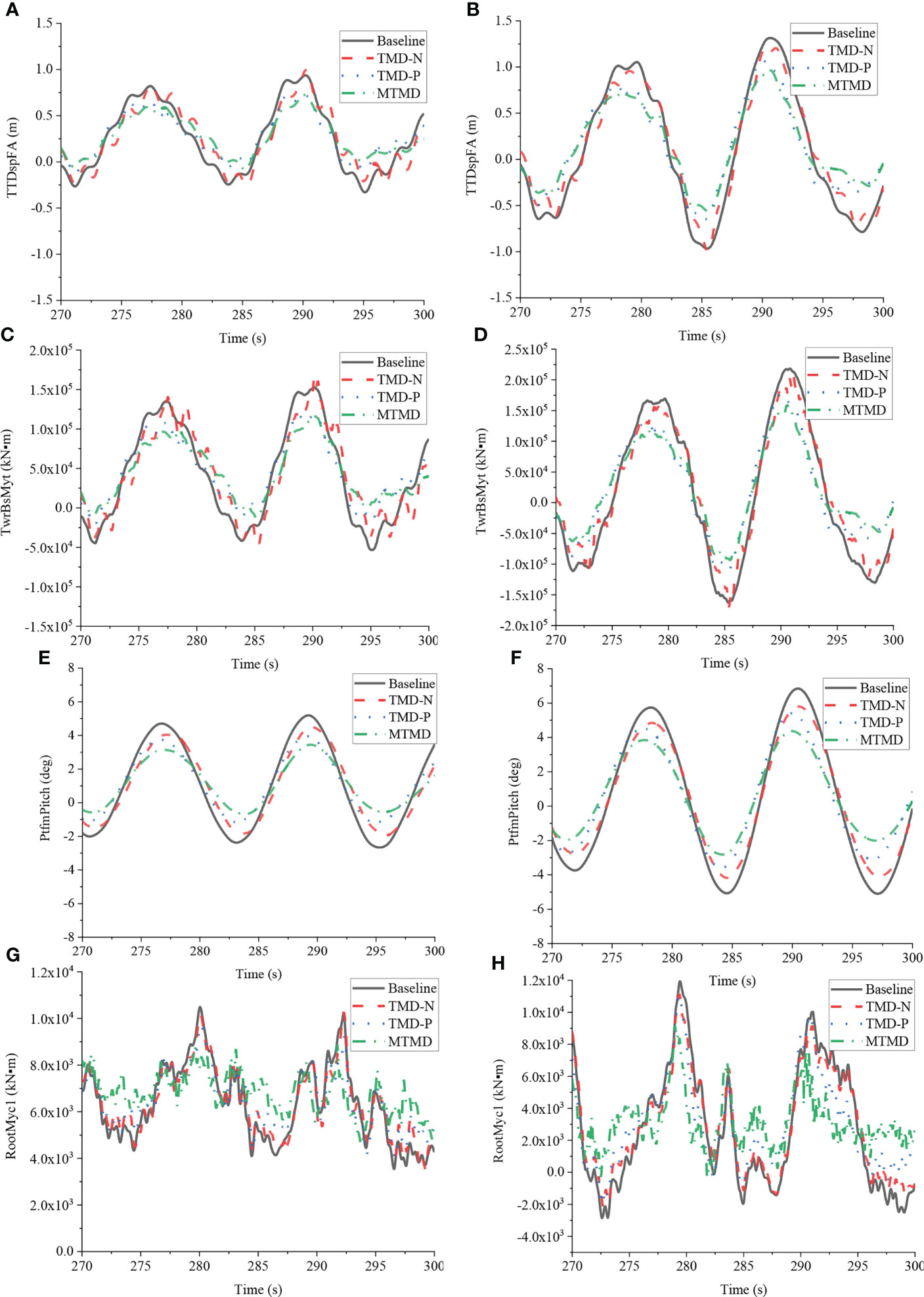
Figure 9 Reduced histories of the barge FOWT under the typical winds and waves using the optimized TMDs and MTMD. (A) Histories of tower top displacement under load case 2; (B) Histories of tower top displacement under load case 4; (C) Histories of tower base bending moment under load case 2; (D) Histories of tower base bending moment under load case 4; (E) Histories of platform pitch motion under load case 2; (F) Histories of platform pitch motion under load case 4; (G) Histories of flapwise bending moment at blade root under load case 2; (H) Histories of flapwise bending moment at blade root under load case 4.
The quantized mitigation effects on the STDs of the selected evaluation indices using the optimized TMDs and the MTMD are depicted in Figure 10. The maximum reduction of the tower top displacement under the typical load cases using the optimized TMD-N in the nacelle is approximately 8.5%. Subsequently, the improved vibration control effects of the optimized platform TMD-P were observed, and the maximum reduction in the response reached 25.9%. It should also be mentioned that the effectiveness of the optimized TMDs is sensitive to the input environmental conditions. By comparing with the other load cases, the minimum reductions are observed under the combined case LC 3 of rated wind, for example, the suppression rate using the platform TMD-P is approximately 7.5% under such a load case, as depicted in Figure 10A. Furthermore, the superiority of the optimized MTMD can be proven, and the reductions in the tower top displacement can still exceed 12.8% even under the combined case LC3.
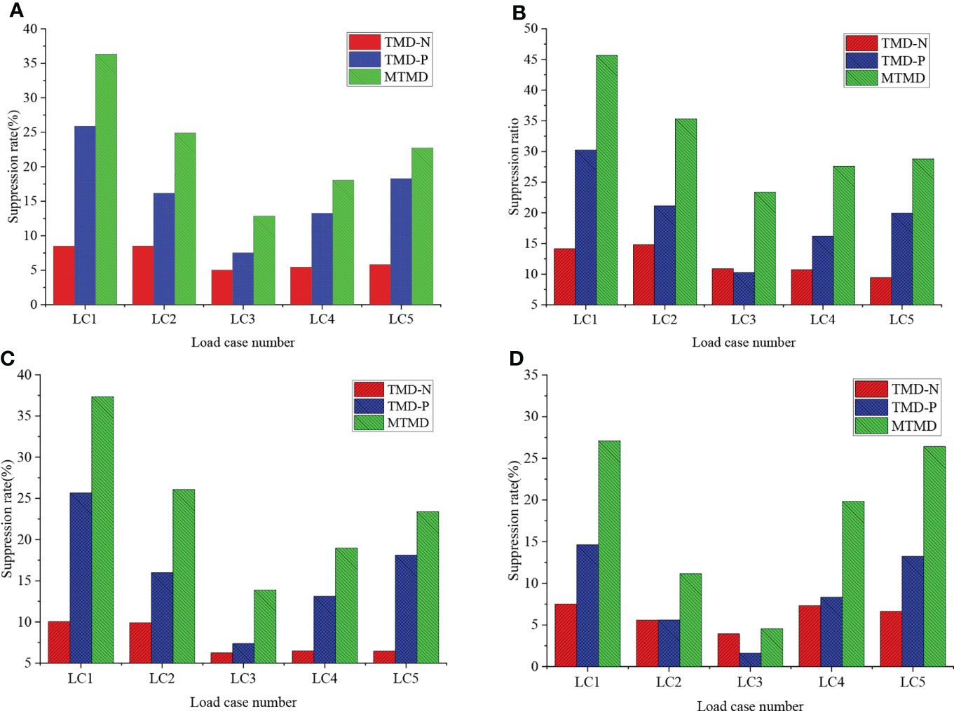
Figure 10 Suppression rates of TMD and MTMD on the standard deviation of evaluation indices. (A) Tower top displacement; (B) Platform pitch angle; (C) Tower base bending moment; (D) Flapwise bending moment at the blade root.
In addition to the comparable vibration control effects of the optimized TMDs on the platform pitch motion under load case 3, the variations in the mitigated STD of the platform pitch motion were approximately consistent with the alleviated tower top displacement, as shown in Figure 10B. The most significant reductions were achieved using the optimized MTMD, which exceeded 23.36% under the combined case LC3. According to Figure 10C, it is quite different from the limited reductions of TMD-N, the optimized TMD-P, and MTMD effectively mitigate the tower base bending moment, particularly using the latter. For example, the maximum reductions in the tower-base bending moment under load cases 1 and 3 reached 36.33% and 12.84%, respectively.
Although the optimized TMDs and MTMD were implemented to alleviate the tower and barge platform motions, the applicability was also evaluated based on the reduction in the local blade responses, as shown in Figure 10D. Compared to TMD-N and TMD-P, the optimized MTMD can achieve the most significant reductions in the flapwise bending moment at the blade root. For example, the reductions in the flapwise bending moment at the blade root under load cases 1 and 5 can reach 27.1% and 26.4%, respectively. Therefore, the optimized TMDs and MTMD can effectively mitigate the barge FOWT motions, and the responses of the rotor blades can also be significantly alleviated using the optimized TMDs and MTMD.
Furthermore, the power spectral densities (PSDs) of the barge FOWT motions under the selected cases 2 and 4 are illustrated in Figure 11. For a normal operation barge FOWT, the barge platform pitch mode dominates the tower and floating platform motions. For both the optimized TMDs and MTMD, the optimized tuning frequencies were approximately consistent with the dominant frequency component, as depicted in Figures 11A–F. Thus, the simulation accuracy of the proposed simplified coupled model for the optimized design of TMDs and MTMD in barge FOWTs can be validated to some extent. In comparison with the optimized one in the nacelle, owing to the larger mass and broader space in the platform, more effective reductions in the frequency domain were achieved using the TMD-P. Based on the positive mitigation effects of the optimized TMD-N and TMD-P, the reductions in the PSDs were further improved using the optimized MTMD comprising two local dampers with a tuned platform pitch frequency and mounted in the nacelle and platform, respectively.
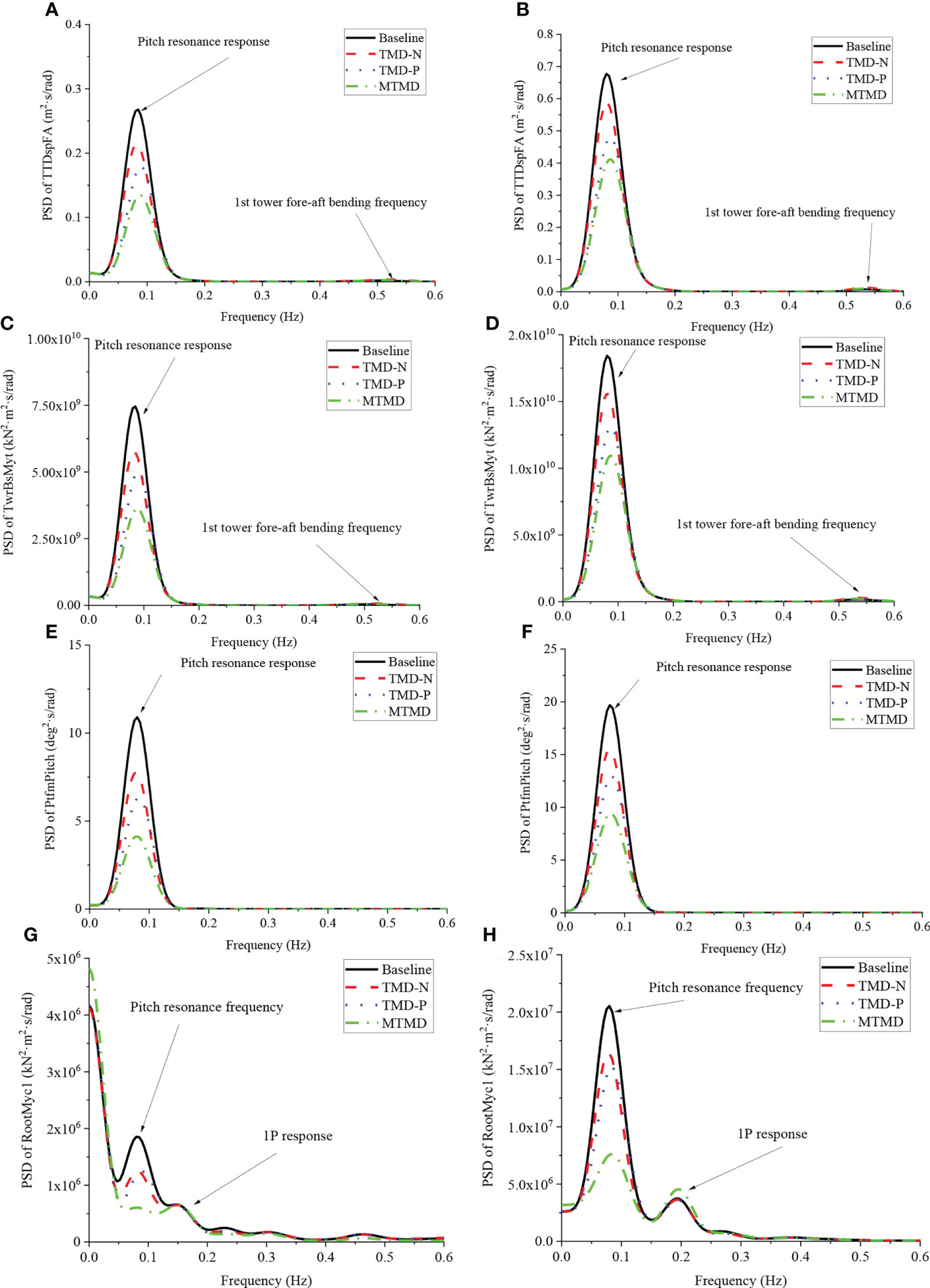
Figure 11 Reduced PSDs of the barge FOWT motions under typical wind and wave conditions using the optimized TMDs and MTMD. (A) PSD of tower top displacement under load case 2; (B) PSD of tower top displacement under load case 4; (C) PSD of tower base bending moment under load case 2; (D) PSD of tower base bending moment under load case 4; (E) PSD of platform pitch motion under load case 2; (F) PSD of platform pitch motion under load case 4; (G) PSD of flapwise bending moment at blade root under load case 2; (H) PSD of flapwise bending moment at blade root under load case 4.
In addition to the RNA rotational frequency, the influence of barge pitch motion on the blade flapwise responses is observed, particularly under load case 4. Therefore, the optimized TMDs and MTMD with a tuned platform pitch frequency can effectively alleviate the blade responses under the selected load cases, and the MTMD is still proven to be the most effective, as shown in Figures 11G, H. Based on the above comparisons, owing to the significant influence of the platform pitch DOF on the barge FOWT responses, the proposed optimization method automatically designates this frequency as the tuning frequency of the TMD and MTMD during the optimization process. Subsequently, the superiority of the optimized TMDs and MTMD was validated according to the reductions of the RNA, tower, and platform responses in the time and frequency domains.
6.3 Impact on output powers
It is of great significance to ensure stability and efficiency of the operation of barge-type FOWT. Figure 12 illustrates the history of the generator output power of the barge FOWT with different TMDs and MTMD above the rated wind speed. The clear positive influence of the optimized TMDs and MTMD on alleviating the output fluctuations can be observed, particularly under load case 4. Owing to the additional structural vibration control strategies, the rated power production was approximately rated under such a load case. The potential benefits of the applied TMDs and MTMD can also be proven from the increased RMSs of the output power depicted in Figure 13. As depicted in the figure, the steady outputs under the majority of the selected load cases generally increase when using the deployed vibration control methods. For example, the RMS of the output under load case 4 is increased to 4952.91 kW, 4958.06 kW, and 4966.43 kW, respectively using the optimized TMD-N, TMD-P, and MTMD, respectively. Moreover, the alleviated output fluctuations are quantized based on the defined suppression rate. As illustrated in Figure 14, it is consistent with the mitigations of FOWT coupled responses and is proven to be more feasible than the related TMD in the nacelle because of the designed larger mass and broader space in the platform. The most effective reductions are achieved using the optimized MTMD, such that the reductions in output fluctuations can exceed 24.14% and 26.21% under load cases 4 and 5, respectively. In comparison with the previously introduced cases, although the mitigation effects are less effective under load case 3, it can still reach 6.89% using the optimized MTMD. Based on the above comparisons, it can be proven that either the structural response or generator output can be effectively suppressed using the proposed TMDs and MTMD. Furthermore, from the perspective of structural safety and output efficiency, the optimized MTMD should be applied to barge FOWT.
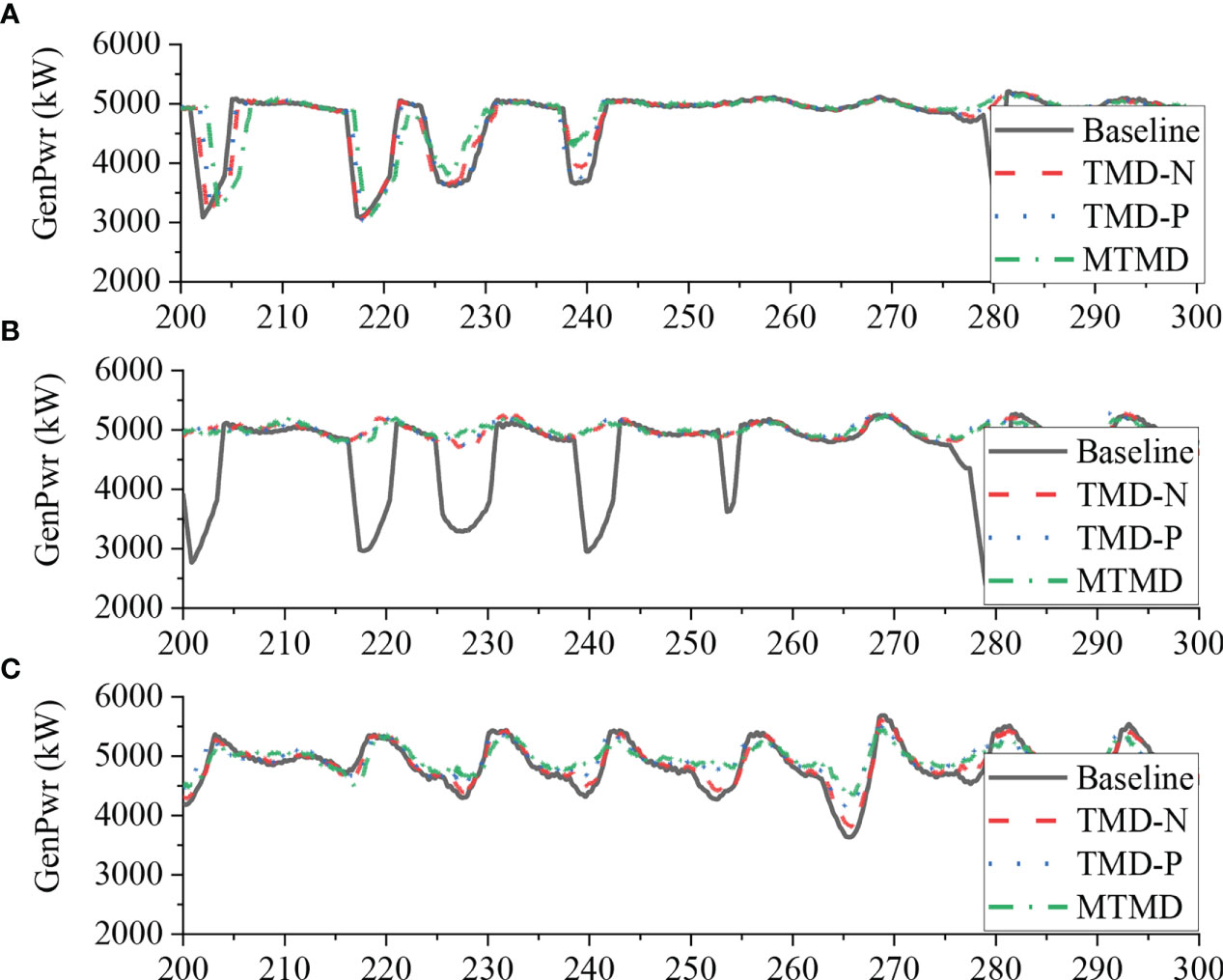
Figure 12 Simulation results of the electrical power output. (A) Load case 3; (B) Load case 4; (C) Load case 5.

Figure 13 Comparison of the RMS value of the output under load cases.
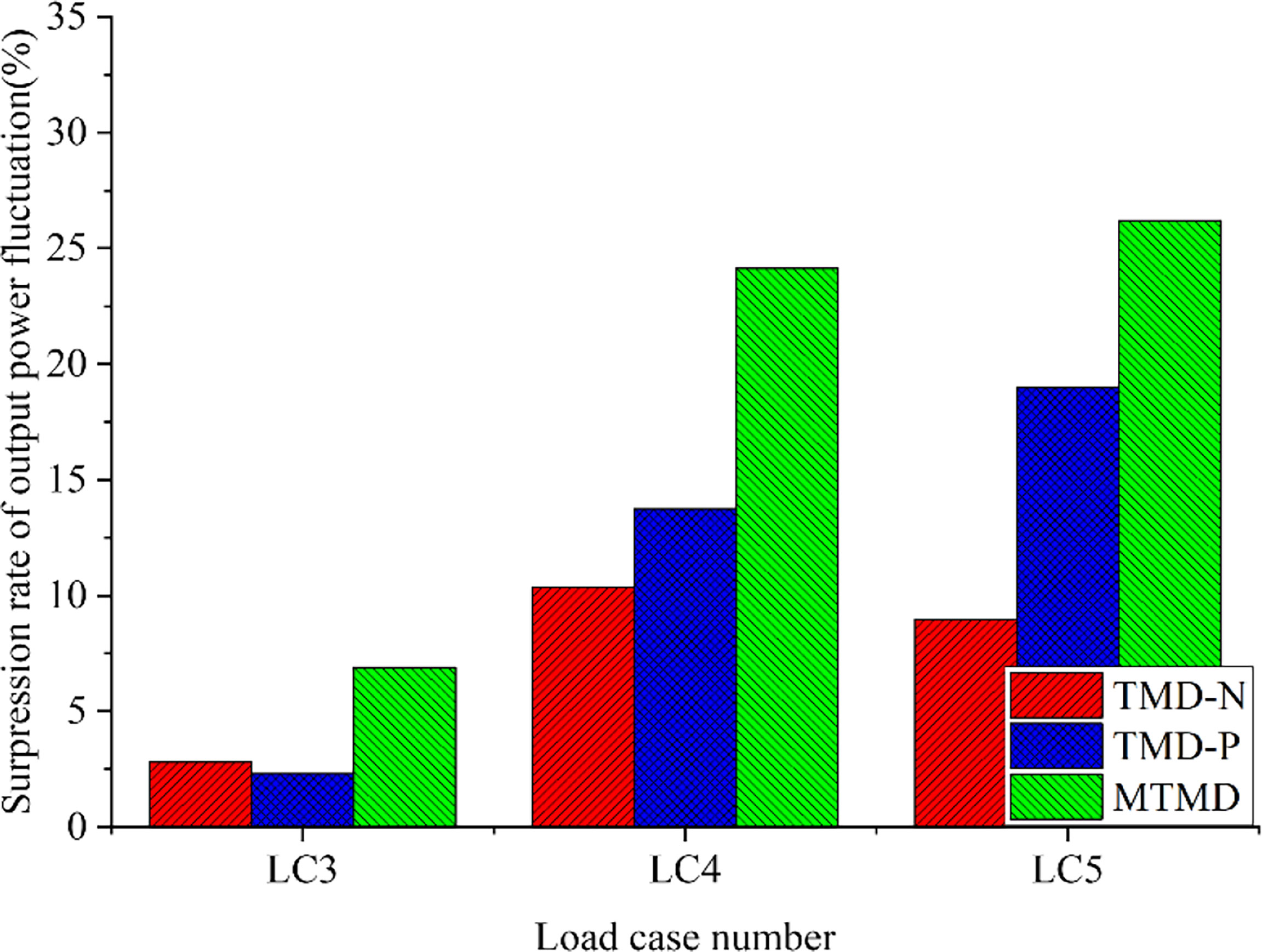
Figure 14 Standard deviations of the output under different load cases.
7 Conclusions
In this study, the effectiveness of TMD and MTMD for the mitigation of barge-type FOWT responses was evaluated based on the established coupled numerical model of a barge FOWT with MTMD. To consider the prominent coupling effects in the design of the TMD and MTMD for the barge FOWT, the tower-first bending and floating-platform pitch DOFs were considered as master DOFs, in addition to the simplified single translational DOF of the local damper. Subsequently, the simplified dynamic model of a barge FOWT with an MTMD was established using the reserved four master DOFs and the Lagrange equation. Moreover, according to the derived coupled governing equation of motion of the MTMD using Kane dynamic theories, the TMD module in the simulation tool FAST-SC was updated. The unknown parameters and simulation accuracy of the simplified model was evaluated based on comparisons of the free decayed motions between the established simplified and coupled numerical models. Subsequently, an optimization method for TMDs and MTMD in the barge FOWT was developed using a genetic algorithm. Furthermore, the applicability and effectiveness of the optimized TMDs and MTMD were assessed based on the reduction of the coupled responses of the barge FOWT. The following conclusions were drawn.
(1) The established simplified model with reserved tower bending and platform pitch DOFs can accurately simulate the support system motions of a barge FOWT dominated by such DOFs compared with the responses of the coupled numerical model. Therefore, from the computational cost perspective, it provides an alternative to the structural vibration control method design for barge FOWT.
(2) Using a genetic algorithm, an artificial intelligence-based optimization method is developed based on the simplified dynamic model of the barge FOWT with MTMD to examine the substantial coupling effects of the FOWT and structural damping in the TMD and MTMD design.
(3) Because of the differences in the stiffness and damping between the optimized MTMD and relevant TMD, the influence of the FOWT coupling effects and structural damping on the optimized TMD and MTMD parameters cannot be considered using the empirical formula. Thus, the effectiveness of the proposed optimization method was demonstrated.
(4) Compared with the optimized TMD in the nacelle, more effective reductions are achieved using the optimized TMD-P because of the designated larger tuned mass and border space in the platform. Notably, owing to the dominant influence of the platform pitch mode on the tower and platform responses, either the tuning frequency of the TMD in the nacelle or the platform is automatically designated as the platform pitch frequency during the optimization process.
(5) The optimized MTMD is the most effective for the barge FOWT compared with the optimized TMDs, which consist of two local dampers with a tuned platform pitch frequency and are mounted in the nacelle and platform.
(6) The applicability of the optimized TMDs and MTMD was evaluated based on the reduced blade responses and improved generator steady output. The FOWT support system motion and the blade responses are effectively mitigated, particularly when using the optimized TMD in the platform and MTMD. Moreover, an improved steady output of the barge FOWT is observed. Therefore, in addition to the mitigation effects on the structural responses, the potential benefits of the steady generator output should also be highlighted.
(7) In future studies, the applicability and accuracy of the proposed optimization method using the simplified dynamic model should be assessed based on additional OWTs, such as typical bottom-fixed OWTs and semi-submersible FOWTs. Moreover, the dynamic model tests of FOWT should be conducted to validate the effectiveness of the optimized TMDs and MTMDs.
Data availability statement
The original contributions presented in the study are included in the article/supplementary material. Further inquiries can be directed to the corresponding author.
Author contributions
Conceptualization: DH. Methodology: DH and BW. Investigation: BW. Writing—first draft preparation, writing, review and editing: DH, WW, XL, KS and YL. Visualization: WW, XL and KS. Supervision and funding acquisition: WW and XL. WW, XL and YL set the objectives of the research, provided guidance for the research, and revised the paper. All authors contributed to the article and approved the submitted version.
Funding
The authors acknowledge support from the Open Fund of Key Laboratory of Far-shore Wind Power Technology of Zhejiang Province (ZOE2020004), Zhejiang Provincial Natural Science Foundation of China (LHY21E090001), and the National Natural Science Foundation of China (Grant Nos. 52071301, 51909238 and 52101334).
Conflict of interest
BW and KS are employed by PowerChina Huadong Engineering Corporation Limited.
The remaining authors declare that the research was conducted in the absence of any commercial or financial relationships that could be construed as a potential conflict of interest.
Publisher’s note
All claims expressed in this article are solely those of the authors and do not necessarily represent those of their affiliated organizations, or those of the publisher, the editors and the reviewers. Any product that may be evaluated in this article, or claim that may be made by its manufacturer, is not guaranteed or endorsed by the publisher.
References
Balog I., Ruti P. M., Tobin I., Armenio V., Vautard R.. (2016). A numerical approach for planning offshore wind farms from regional to local scales over the Mediterranean. Renewable Energy 85, 395–405. doi: 10.1016/j.renene.2015.06.038
Bredmose H., Lemmer F., Borg M., Pegalajar-Jurado A., Mikkelsen R. F., Larsen T. S., et al. (2017). The triple spar campaign: Model tests of a 10MW floating wind turbine with waves, wind and pitch control. Energy Proc. 137, 58–76. doi: 10.1016/j.egypro.2017.10.334
Buckley T., Watson P., Cahill P., Jaksic V., Pakrashi V. (2018). Mitigating the structural vibrations of wind turbines using tuned liquid column damper considering soil-structure interaction. Renewable Energy 120, 322–341. doi: 10.1016/j.renene.2017.12.090
Butterfield S., Musial W., Jonkman J. M., Sclavounos P. (2007). Engineering challenges for floating offshore wind turbines (CO, USA: National Renewable Energy Laboratory (NREL): Golden).
Chen J., Georgakis C. T. (2013). Tuned rolling-ball dampers for vibration control in wind turbines. J. Sound Vib. 332 (21), 5271–5282. doi: 10.1016/j.jsv.2013.05.019
Chen J., Liu Y., Bai X. (2015). Shaking table test and numerical analysis of offshore wind turbine tower systems controlled by TLCD. Earthq. Eng. Eng. Vib. 14 (1), 55–75. doi: 10.1007/s11803-015-0006-5
Colwell S., Basu B. (2009). Tuned liquid column dampers in offshore wind turbines for structural control. Eng. Struct. 31 (2), 358–368. doi: 10.1016/j.engstruct.2008.09.001
Goupee A. J., Kimball R. W., Dagher H. J. (2017). Experimental observations of active blade pitch and generator control influence on floating wind turbine response. Renewable Energy 104, 9–19. doi: 10.1016/j.renene.2016.11.062
He E. M., Hu Y. Q., Zhang Y. (2017). Optimization design of tuned mass damper for vibration suppression of a barge-type offshore floating wind turbine. Proc. Inst. Mech. Eng. Part M J. Eng. Maritime Environ. 231 (1), 302–315. doi: 10.1177/1475090216642466
He J., Jin X., Xie S. Y., Cao L., Lin Y., Wang N. (2019). Multi-body dynamics modeling and TMD optimization based on the improved AFSA for floating wind turbines. Renewable Energy 141, 305–321. doi: 10.1016/j.renene.2019.04.005
IEC. (2009). Wind turbines, 2009. part 3: Design requirements for offshore wind turbines (Geneva, Switzerland: International Electrotechnical Commission), 61400–61403.
Jin X., Xie S., He J., Lin Y., Wang Y., Wang N. (2018). Optimization of tuned mass damper parameters for floating wind turbines by using the artificial fish swarm algorithm. Ocean Eng. 167, 130–141. doi: 10.1016/j.oceaneng.2018.08.031
Jonkman J. (2008). Dynamics modeling and loads analysis of an offshore floating wind turbine (University of Colorado at Boulder: National Renewable Energy Laboratory). PhD Thesis.
Jonkman B. J., Butterfield S., Musial W., Scott G. (2009). TurbSim user’s guide (United States: National Renewable Energy Laboratory). NREL/TP-500-46198.
Jonkman J. M., Butterfield S., Musial W., Scott G. (2009). Definition of a 5MW reference wind turbine for offshore system development (No. NREL/TP-500-38060). (United States: National Renewable Energy Lab. (NREL), Golden, CO).
Kaimal J. C., Wyngaard J. C., Izumi Y., Coté O. R. (1972). Spectral characteristics of surface-layer turbulence. Q. J. R. Meteorol Soc. 98 (417), 563–589. doi: 10.1002/qj.49709841707
Larsen T. J., Hanson T. D. (2007). A method to avoid negative damped low frequent tower vibrations for a floating, pitch controlled wind turbine. J. Phys.: Conf. Ser. 75 (1), 012073. doi: 10.1088/1742-6596/75/1/012073
Lee J., Zhao F. (2022). Global wind report 2022. tech. rep (Brussels, Belgium: Global Wind Energy Council).
Li J., Zhang Z., Chen J. (2012). Experimental study on vibration control of offshore wind turbines using a ball vibration absorber. Energy Power Eng. 4 (03), 153. doi: 10.4236/epe.2012.43021
Li C., Zhuang T., Zhou S., Xiao Y., Hu G. (2017). Passive vibration control of a semi-submersible floating offshore wind turbine. Appl. Sci. 7 (6), 509. doi: 10.3390/app7060509
Manzano-Agugliaro F., Sánchez-Calero M., Alcayde A., San-Antonio-Gómez C., Perea-Moreno A. J., Salmeron-Manzano E. (2020). Wind turbines offshore foundations and connections to grid. Inventions 5 (1), 8. doi: 10.3390/inventions5010008
Mohammadi E., Fadaeinedjad R., Moschopoulos G. (2018). Implementation of internal model based control and individual pitch control to reduce fatigue loads and tower vibrations in wind turbines. J. Sound Vib. 421, 132–152. doi: 10.1016/j.jsv.2018.02.004
More J. (1978). The levenberg–marquardt algorithm: implementation and theory. Numer Anal. 105–116. doi: 10.1007/BFb0067700
Murtagh P. J., Ghosh A., Basu B., Broderick B. M. (2008). Passive control of wind turbine vibrations including blade/tower interaction and rotationally sampled turbulence. Wind Energy 11 (4), 305–317. doi: 10.1002/we.249
Namik H., Stol K. (2011). Performance analysis of individual blade pitch control of offshore wind turbines on two floating platforms. Mechatronics 21 (4), 691–703. doi: 10.1016/j.mechatronics.2010.12.003
Njiri J. G., Soeffker D. (2016). State-of-the-art in wind turbine control: Trends and challenges. Renewable Sustain. Energy Rev. 60, 377–393. doi: 10.1016/j.rser.2016.01.110
Park S., Glade M., Lackner M. A. (2020). Multi-objective optimization of orthogonal TLCDs for reducing fatigue and extreme loads of a floating offshore wind turbine. Eng. Struct. 209, 110260. doi: 10.1016/j.engstruct.2020.110260
Raach S., Schlipf D., Sandner F., Matha D., Cheng P. W. (2014). “Nonlinear model predictive control of floating wind turbines with individual pitch control,” in 2014 American Control Conference. Portland, USA: IEEE.
Si Y., Karimi R. H., Gao H. (2014a). Modelling and optimization of a passive structural control design for a spar-type floating wind turbine. Eng. Struct. 69, 168–182. doi: 10.1016/j.engstruct.2014.03.011
Si Y., Karimi H. R., Gao H. (2014b). “Parameter tuning for nacelle-based passive structural control of a spar-type floating wind turbine,” in In IECON 2013-39th Annual Conference of the IEEE Industrial Electronics Society. IEEE.
Snyder B., Kaiser M. J. (2009). Ecological and economic cost-benefit analysis of offshore wind energy. Renewable Energy 34 (6), 1567–1578. doi: 10.1016/j.renene.2008.11.015
Stewart G. M. (2012). Load reduction of floating wind turbines using tuned mass dampers (Amherst, MA: University of Massachusetts). MSC Thesis.
Stewart G., Lackner M. (2013). Offshore wind turbine load reduction employing optimal passive tuned mass damping systems. IEEE Trans. Control Syst. Technol. 21 (4), 1090–1104. doi: 10.1109/TCST.2013.2260825
Wakui T., Yoshimura M., Yokoyama R. (2017). Multiple-feedback control of power output and platform pitching motion for a floating offshore wind turbine-generator system. Energy 141, 563–578. doi: 10.1016/j.energy.2017.09.100
Willis D. J., Niezrecki C., Kuchma D., Hines E., Arwade S. R., Barthelmie R. J., et al. (2018). Wind energy research: State-of-the-art and future research directions. Renewable Energy 125, 133–154. doi: 10.1016/j.renene.2018.02.049
Yang J., He E. M. (2020). Coupled modeling and structural vibration control for floating offshore wind turbine. Renewable Energy 157, 678–694. doi: 10.1016/j.renene.2020.05.075
Yang J., He E. M., Hu Y. Q. (2019). Dynamic modeling and vibration suppression for an offshore wind turbine with a tuned mass damper in floating platform. Appl. Ocean Res. 83, 21–29. doi: 10.1016/j.apor.2018.08.021
Keywords: offshore wind turbine, barge-type platform, vibration control, MTMD, coupled analysis
Citation: Wang B, Han D, Wang W, Li X, Shen K and Li Y (2022) Modeling and optimization of multiple tuned mass dampers for a barge-type floating offshore wind turbine. Front. Mar. Sci. 9:994848. doi: 10.3389/fmars.2022.994848
Received: 15 July 2022; Accepted: 13 September 2022;
Published: 29 September 2022.
Edited by:
Wei Cheng, Center, Taipei, TaiwanReviewed by:
Yinlong Hu, Hohai University, ChinaAgathoklis Giaralis, City University of London, United Kingdom
Copyright © 2022 Wang, Han, Wang, Li, Shen and Li. This is an open-access article distributed under the terms of the Creative Commons Attribution License (CC BY). The use, distribution or reproduction in other forums is permitted, provided the original author(s) and the copyright owner(s) are credited and that the original publication in this journal is cited, in accordance with accepted academic practice. No use, distribution or reproduction is permitted which does not comply with these terms.
*Correspondence: Dongdong Han, aGFuZGRAbWFpbC5kbHV0LmVkdS5jbg==