- 1College of Engineering, Ocean University of China, Qingdao, China
- 2Shandong Provincial Key Laboratory of Ocean Engineering, Ocean University of China, Qingdao, China
- 3School of Civil and Environmental Engineering, Ningbo University, Ningbo, China
Submerged pile groups are important components of complex piers in hydraulic engineering and are analogs for a range of subsea structures. These may sustain severe damages from local scour. The velocity intensity (U / Uc, the ratio of critical velocity to mean velocity) and aspect ratio (H / Dp, the ratio of pile height to pile diameter) are critical variables in this scour process. However, previous studies on scour around submerged pile groups were conducted in clear-water conditions (U / Uc < 1). In addition, many research studies are being conducted in shallow water flow conditions, which cannot eliminate the effect of the water depth on the scour process. Thus, these research studies cannot directly be applied to live-bed scour around submerged structures. To expand the velocity intensity and aspect ratio of scour around submerged pile groups, flume experiments were conducted with uniform quartz sand in both clear-water and live-bed conditions. Pile groups with different heights are adopted as experimental models. An improved time factor for both clear-water and live-bed scour around submerged structures is determined with the present experiments to extrapolate the scour depth of the present work to the equilibrium scour depth. This new time factor is then tested with experimental data from the literature. The tests demonstrate that this new time factor can reliably predict the scour process and equilibrium scour depth for submerged structures. Empirical relationships to demonstrate the effects of the studied variables including the equilibrium scour depth, scour area, and scour volume are presented. Different methods to predict the effects of the velocity intensity and aspect ratio on the scour depth are compared based on the present work. Furthermore, a correction coefficient is proposed to illustrate the effect of aspect ratio on scour depth. Then, equations of scour area and volume are derived according to the present experiments.
1 Introduction
Pile groups are widely used as supporting structures in coastal and ocean engineering, e.g., cross-sea bridges, platforms, and wind turbines. The protection method and its assessment have been paid special attention by many researches (Fazeres-Ferradosa et al., 2019; Wu et al., 2020; Fazeres-Ferradosa et al., 2021). Piers become submerged when the flow depth is larger than the structure height (Dey et al., 2008). Occasionally, these are designed as submerged structures. In addition, submerged pile groups are essential components for complex piers. Superposition methods (Salim and Jones, 1996; Richardson and Davis, 2001; Sheppard and Glasser, 2004; Arneson et al., 2012) are widely adopted to evaluate the scour depth around complex piers. Evaluating the scour depth around submerged pile groups is an important step for this method. Here, the typical superposition methods by Arneson et al. (2012) and Sheppard and Renna (2005) are described in detail.
The fundamental design adopted by the superposition methods in Arneson et al. (2012) is the calculation of the scour depth of different components expressed as
where Dse is the equilibrium scour depth of piers. Dse,col, Dse,pc, and Dse,pg are the scour depths of the column structure, pile cap structure, and pile-group structure, respectively.
Each component is calculated based on the scour equation of HEC-18 (Richardson and Davis, 2001), which is expressed as
Where Dp is the pier diameter;d is the water depth; Kbed is a factor equal to 1.1 for clear-water scour, plane bed, or small dunes;Kα is a factor for the angle of attack and is equal to 1.0 for aligned flow; and Ks is the shape factor and is equal to 1.0 for a circular or round nose and 1.1 for rectangular piers. U is the mean flow velocity, and g is the gravitational acceleration.
The Florida Department of Transportation (FDOT) (Sheppard and Renna, 2005) calculates scour using another superposition method, expressed as
where De is the equivalent diameter of complex piers. De,col, De,pc, and De,pg are the equivalent diameter of the column structure, pile cap structure, and pile-group structure, respectively.
The final step of the FDOT is to substitute De as Dp in the FDOT single pier equation. This can be expressed by
where f1, f2, and f3 are the correction factors for the flow depth, velocity intensity, and sediment size, respectively.
The mechanics of scour around submerged pile groups are complex because pile-group effects depend on the pile spacing, velocity intensity (Yang et al., 2020), and the ratio of pile height to pile diameter [also called aspect ratio (H / Dp)]. Typically, each of these parameters is assumed to have an independent effect on the scour depth (Melville and Coleman, 2000).
where the coefficients on the right are the correction factors for velocity intensity, flow depth, sediment size, sediment gradation, pile shape, pile alignment, and time. Similar equations with different factors have been proposed by many other researchers (Melville and Sutherland, 1988; Salim and Jones, 1996; Melville, 1997; Richardson and Davis, 2001; Arneson et al., 2012).
Many research studies have contributed to a better understanding of the scour process. Salim and Jones (1996) conducted a variety of studies on the local scour depth around submerged square pile groups under the threshold velocity. They derived a correction factor (Eq. 6) to adjust the equation designed for predicting the scour depth of piers to that for predicting submerged pile groups,
where Kh is the correction factor for the height of pile groups, Dse,∞ is the equilibrium scour depth of infinitely tall pile groups, and H is the pile height in the submerged condition.
Correction factor with power form as Eq. 6 has not been widely adopted and improved because square pile groups are not as widely used as circular pile groups. Moreover, more experiments are needed to conclude and verify the correction factor. Nevertheless, correction factors for submerged structures have been widely used in later research.
Sumer and Fredsøe (2002) recommended the following correction factor for the aspect ratio:
where β = 0.55 is an empirical constant in clear-water conditions. Zhao et al. (2010) conducted experiments both in clear-water (U / Uc = 0.99) and live-bed conditions (U / Uc = 1.23) focusing on submerged piles (0.25 < H / Dp <8.33). To compare their experimental data with Eq. 3, concluding a larger β is suitable in the live-bed condition. Thus, it is evident that β is related to the velocity intensity and that a constant value (0.55) is not suitable for the live-bed condition. The experimental water depth was maintained at 0.5 m, and d / Dp was 5 and 8.3. These can prevent the influence of water depth on the scouring process.
To expand the velocity intensity range and an aspect ratio range of scour around submerged piles, an O-tube (Cheng et al., 2014) was used by Yao et al. (2018) to study the effect of velocity intensity (ranging from 0.99 to 5.75) and aspect ratio (ranging from 0.1 to 7.0) on the scour around submerged structures. The water depth in their experiments was 1.0 m in the O-tube. This was 8.7 times larger than the pile diameter (0.115 m). Thus, the effect of water depth can also be eliminated from the influence factor. Only the aspect ratio (H / Dp) was required to represent the effect of pile height as in Zhao et al. (2010). With regard to the live-bed condition, β is a function of the relative Shields parameter (θ / θcr). (θ / θcr)0.5 is equal to the ratio of the friction velocity to the critical friction velocity, as well as the velocity intensity,
There are few experimental studies on live-bed scour around submerged pile groups. Most studies were conducted under the threshold velocity. This was because of the assumption that the maximum scour depth occurs when the flow velocity is close to the threshold velocity in the clear-water condition. This assumption has been demonstrated by many studies in the single pile case under the clear-water condition (Melville, 1984; Melville and Sutherland, 1988; Sheppard et al., 2004). When the velocity intensity increases under the live-bed condition, the scour depth decreases to a turning point and then increases continuously. This phenomenon has been observed and explained in the case of single pile and submerged structures by many research studies (Melville, 1984; Sheppard and Miller, 2006; Yao et al., 2018).
When the velocity is close to and above the critical velocity, transported sand and ripples from upstream enter the scour hole and limit its continuous growth. Thus, the maximum scour depth decreases with the increase in velocity intensity. However, this trend ends with a continuous increase in velocity intensity because an increase in velocity intensity also results in a larger local scour depth around piles. The velocity intensity corresponding to the minimum scour depth in the live-bed condition is approximately 1.3–1.8 (Melville, 1984; Yao et al., 2018). Beyond this, the effect of the increase in scour by the increase in velocity intensity dominates the scour process. The scour depth continues to increase with the velocity intensity.
This phenomenon may be different for scour around pile groups and submerged pile groups because the pile-group reinforcing effect would strengthen the scouring depth of the front pile compared with single pile or submerged structures. Meanwhile, the sand transported from upstream attains close to a constant value for a given constant current. Thus, this strong scouring process and similar sand transportation should result in a turning point that is smaller than that for single pile or submerged structures.
The current research on submerged pile groups uses a similar velocity intensity. In addition, the water depth is inadequate to prevent it from affecting the scour process. The flow shallowness needed to be considered in the experiments of Amini et al. (2012). This is because the minimum ratio of water depth to equivalent pile diameter (d / nDp) is 1.33. Thus, another variable (namely, submerged ratio Sr = H / d) is required to represent the complex interaction between water depth and pile height. The following correcting factors were proposed by Amini et al. (2012) based on the experimental data and the control tests.
Best fitting:
Envelope fitting:
A similar correction factor was used in Dey et al. (2008) with a similar polynomial form. Galan et al. (2018) conducted experiments focusing on submerged pile groups under a steady threshold velocity. The studied variables were submerged ratio, skewed angle, and pile arrangements. The ratio of water depth to equivalent pile diameter (d / nDp) was 0.5. Thus, it could not eliminate the effect of water depth on the scour process.
The review of previous research reveals that no experimental study has been conducted on submerged pile groups in the live-bed condition. Research is urgently required for a detailed explanation of the scouring mechanism and scouring characteristics of pile groups in live-bed conditions as well. A correcting factor that considers the pile height as a factor isolated from the velocity intensity has been demonstrated to be ineffective (Zhao et al., 2010; Zhao et al., 2012; Yao et al., 2018).
This work focuses on the aspect ratio and velocity intensity, and their effects on submerged pile-group scour.
2 Framework for Analysis
The maximum scour depth of submerged pile groups in rectangular channels at a given time instant t can be described by the following set of independent variables (Lança et al., 2013):
where φ denotes function, Dst is the maximum scour depth of the pile group at the time instant t, d is the approaching flow depth, U is the approaching flow velocity, g is the gravitational acceleration, ρs is the sediment density, ρw is the water density, μ is the dynamic viscosity coefficient, D50is the median particle size, σg is the sediment gradation, Uc is the approaching flow velocity for the threshold of sediment entrainment, Dp is the individual pile diameter, B is the flume width,S is the pile spacing, H is the height of the pile groups, Ks is the shape factor of individual piles, m is the number of rows in the groups, n is the number of columns in the groups, and α is the pile-group skew angle. In a fully developed turbulent flow, the viscous force would not influence the temporal development of scour. Uc is a function of D50, σg, ρs, ρw, and g. By non-dimensionalizing Eq. 11,
Many assumptions are adopted to simplify the problem and focus on the main research themes:
1. For , the scouring would attain the maximum (Melville and Chiew, 2000; Melville and Coleman, 2000).2. For D 50 >0.6mm, σg <1.5 , the sand bed would not retain any ripple upstream of the structures in a clear-water region. The sand can be considered uniform (Melville and Coleman, 2000).
3. Only quartz sand is used during the experiments. Hence = 2.64 (constant).
4. For B/d≈~5 , the effects of the wall and the cross-sectional shape are negligible; the approaching velocity field can be considered two-dimensional at the central section of the channel (Lança et al., 2013; Galan et al., 2018).
5. For nDp or De< 0.1B (De = equivalent diameter of pile groups), the contraction effect is negligible (Raudkivi and Ettema, 1983; Melville and Sutherland, 1988; Melville and Chiew, 1999).
6. For , the equivalent diameter of pile groups (De) should be less than nDp. Thus, , and the water depth would not affect the final equilibrium scour depth around submerged pile groups (Ettema, 1980; Chiew, 1984; Melville and Sutherland, 1988; Larsen et al., 2017).
7. can be considered to be negligible when the flow is completely turbulent (Ettema et al., 1998).
Thus, Eq. 12 can be expressed as follows:
In addition, the expressions for the scour area and scour volume can be simplified as follows:
where Ast is the scour area around pile groups, Vst is the scour volume around pile groups, θ is the slope angle, and KA and KV are the correction factors for the different scour slopes.
The equivalent diameter of pile groups (De) can be expressed as
Then, Eqs. 13–15 can be expressed as
For the equilibrium scour depth, t does not influence the scour depth, area, or volume. These can be expressed as
Thus, Dse / Ds is a function of velocity intensity and aspect ratio. Ase and Vse are functions of velocity intensity, slope angle, correct factor for scour slope, and aspect ratio.
3 Experimental Setup and Procedures
3.1 Experimental Facilities and Instrumentation
The experiments were carried out in a rectangular glass-sided flume with a length, width, and depth of 60, 3, and 1.5 m, respectively. It is located at Shandong Provincial Key Laboratory of Ocean Engineering, Ocean University of China, China. Computer-controlled recycling pumps are installed in the flume to control the water flow accurately. A sand barrier and perforated plates are used in the rear section of the flume to trap the bedload sediment. The suspended sediment is recycled with the water by pumps. For experiments under the live-bed condition, the velocity intensity (U / Uc) is marginally higher than one, and highly marginal global scour occurs. The maximum bed variation rate in the inlet of sand recession is determined experimentally to be approximately 0.3 mm/h. Therefore, sediments are added manually every 0.5 h in the inlet of the sand recession to diminish the impact of global scour.
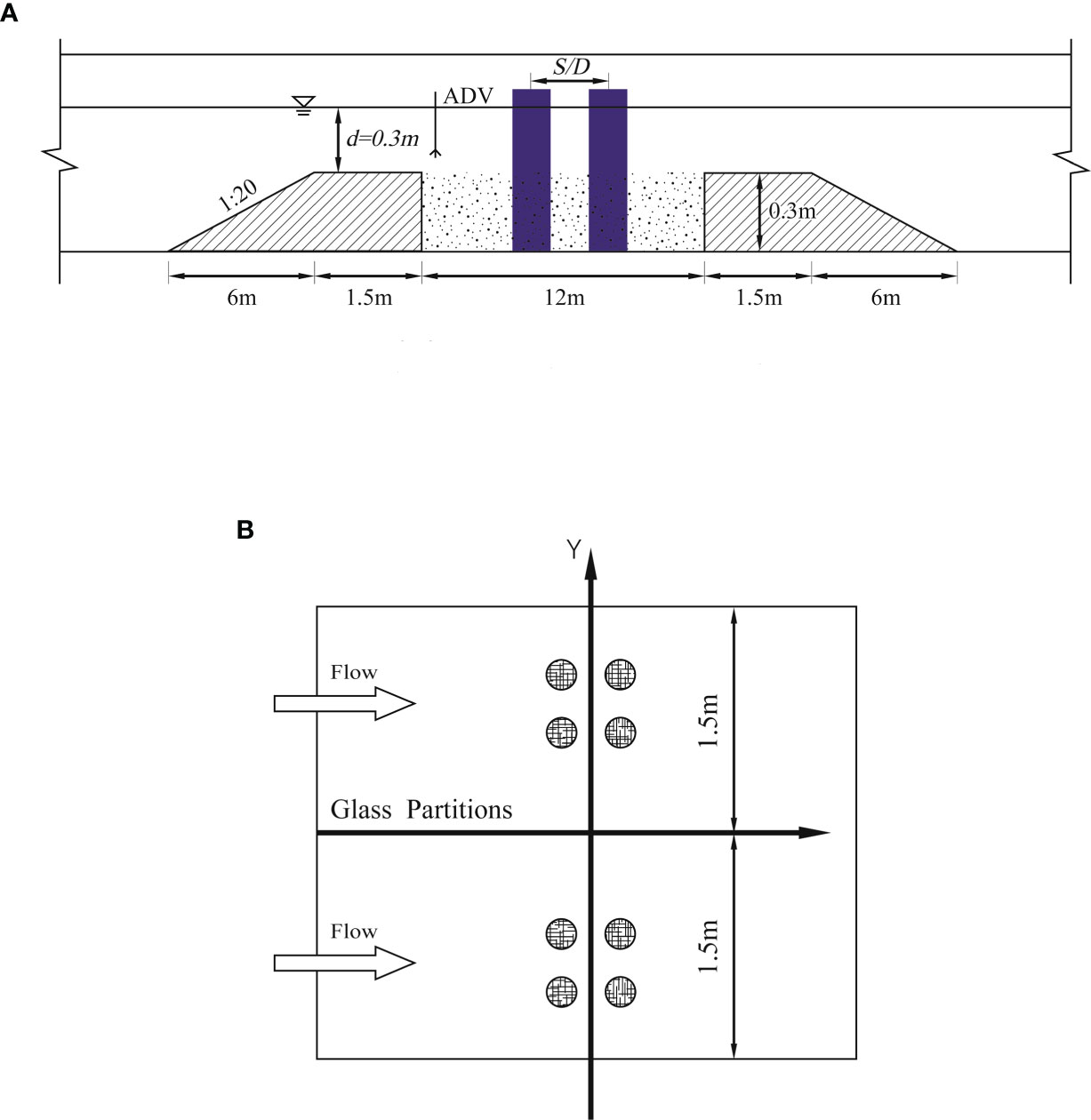
The flume is equipped with a 12-m-long recess that is filled with sediment of uniform thickness (0.3 m). The sand bed recess is located 25.5 m downstream of the flume inlet. The test models are installed in the middle of the sediment recess 30.5 m downstream of the flume inlet. Both sides of the recess have a slope of 1:20 and a 1.5-m connection flat. To utilize the wide flume fully, glass partitions are used to separate the flume to conduct two experiments simultaneously (see Figure 1).
The flow depth is maintained at 0.30 m for all the experiments. NorTek acoustic Doppler velocity (ADV) probes are installed on both sides to measure the velocity. During the tests, two ADVs are placed 1 m upstream from the model to measure the average velocity and ensure that the experimental condition remains unaltered. The two ADVs are also used to measure scour depth with a precision of 0.1 mm. Cohesionless uniform sediment is used as bed material, with a median particle size (D50) of 0.66 mm, no-ripple forming in clear-water conditions, and geometric SD of particles σg of 1.33, no armoring layer, critical shear velocity θc) of 0.03, and critical flow velocity (Uc) of 0.32 m/s. This has also been demonstrated by a sand-entrainment experiment wherein the current velocity was improved gradually.
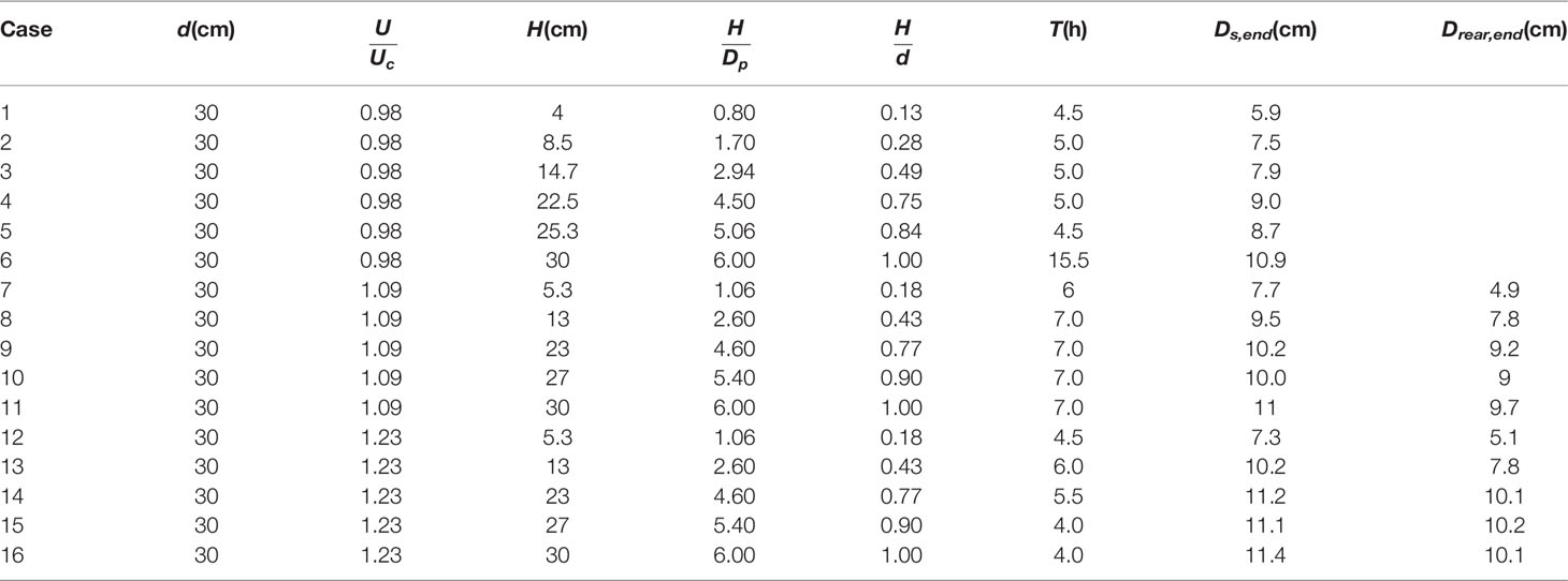
The velocity intensities in the present experiments are 0.98, 1.09, and 1.23. The detailed experimental conditions and results are presented in Table 1. The maximum model-width nDp or De is close to 7% of the flume width to prevent contraction effects (Raudkivi and Ettema, 1983; Melville and Sutherland, 1988; Melville and Chiew, 1999). The ratio of flume width to water depth (B / d) is close to five (Lança et al., 2013). This ensures that the effects of the wall and the cross-sectional shape are negligible and that the approaching velocity field is two-dimensional at the central section of the channel. The pile-group model is arranged 2 × 2 with Dp = 0.05 m in all the experiments. The pile spacing is maintained constant (S / Dp = 2) for all the experiments. The experimental durations (T) in the clear-water region are maintained at 4–7 h for most of the experiments. Each experiment requires 15.5 h to verify the time factor. The experimental durations for the live-bed condition are 4–7 h. The durations are considered adequate because scour in the live-bed condition is significantly faster than that in clear-water conditions.
3.2 Experimental Procedures
A stringent procedure is followed throughout the tests to ensure the authenticity of experimental results and exclude the effects of various parameters on the equilibrium scour depth and rate of scour. The experimental procedure is outlined below.
Pre-experiment:
1. Level the sand bed and arrange the model in the flume.
2. Fill the flume gradually and permit the standing until the air trapped in the sand has been expelled. This procedure generally requires at least 2–3 h for an observation of the sand condition through the glass sidewall.
3. Examine the instrumentation.
4. Monitor the bedforms during the live-bed experiments.
5. Monitor the ripple development, drain the flume, and relevel the bed every 1 h in the live-bed scour conditions to prevent ripples in front of the model that would affect the scour program around the models.
During the experiment:
1. Gradually increase the flow velocity of the flume to prevent abrupt variation in the pump rotation rate, which may cause an abrupt increase in velocity.
2. Measure the temporal development of scour with ADV, underwater cameras, and scale paper.
3. Measure the velocity, water depth, and temperature.
Post-experiment:
1. Gradually decrease the flow velocity to zero and measure the topography with ADV.
2. Gradually drain the flume to prevent damage to the topography.
3. Observe and record the bed condition throughout the flume.
4. Survey the topography through measuring tapes as an additional survey of the bling area for ADV.
5. Examine and analyze the experimental data.
4 Results and Discussion
4.1 Temporal Development of the Scour Depth
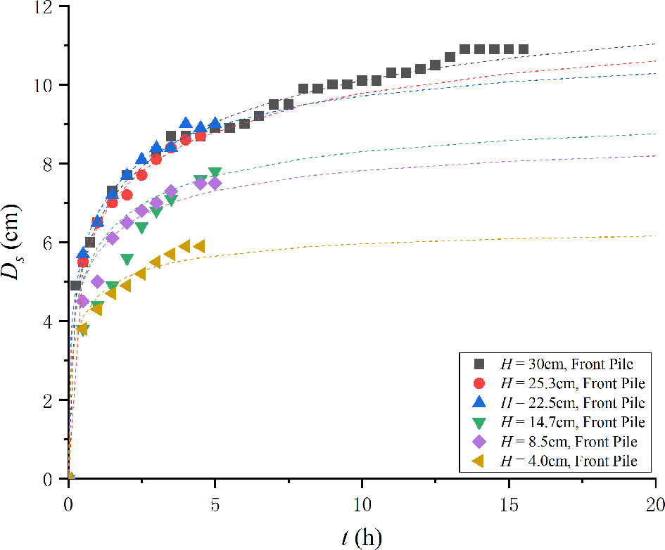
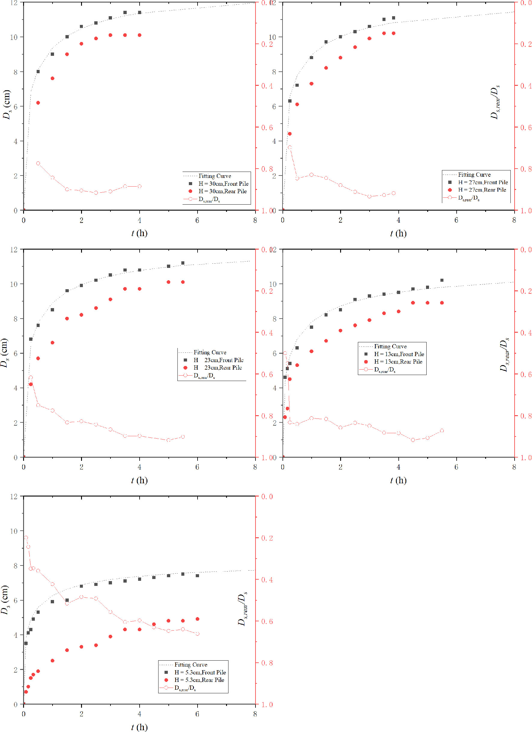
The temporal developments of the maximum scour depth around submerged pile groups are illustrated in Figure 2.
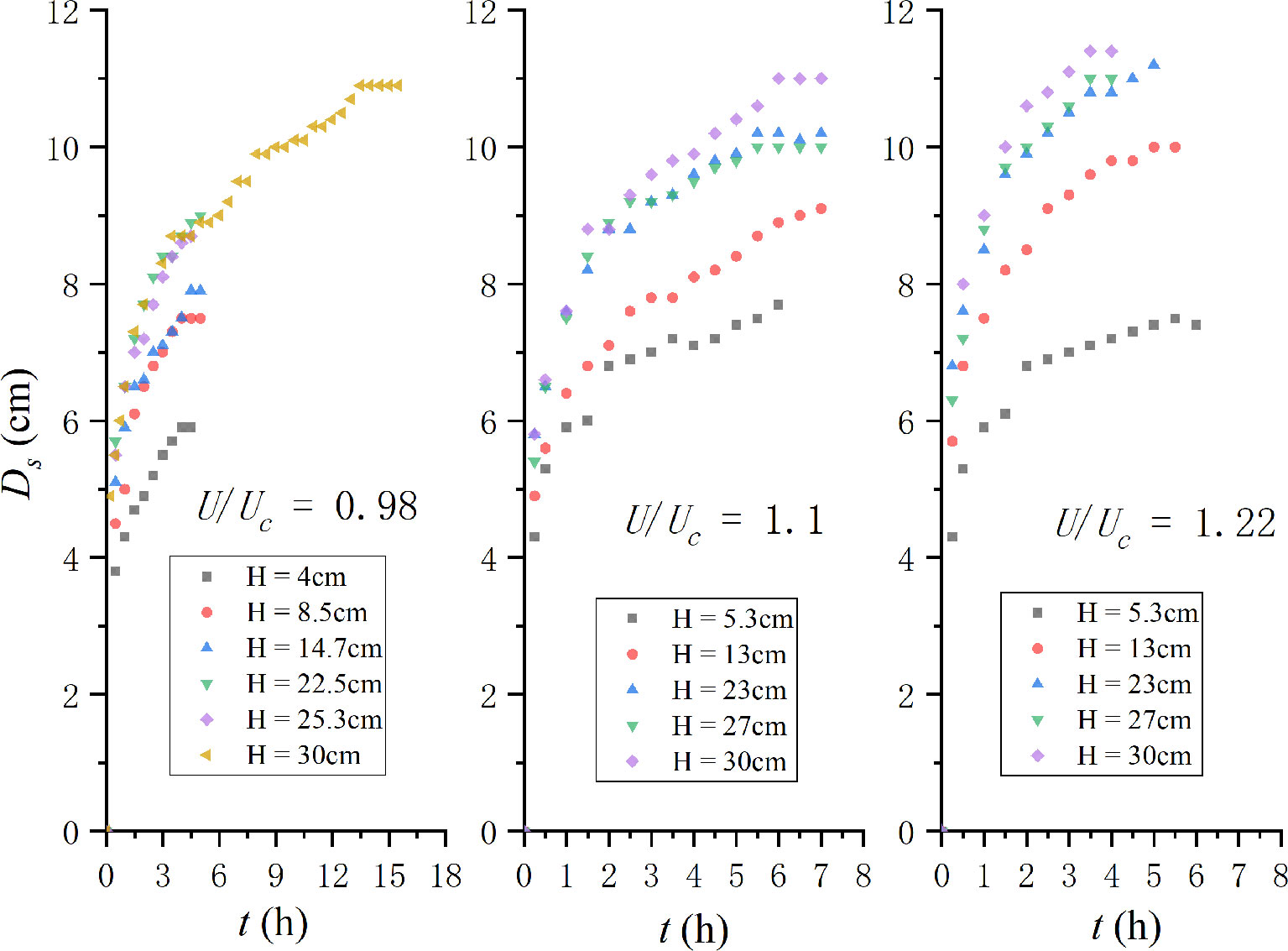
Figure 2 Temporal development of maximum scour depth around pile groups in the present experiments (H = 30 cm represents the non-submerged pile groups).
The maximum scour depth increases with the increase in pile height for all the velocity intensities. The non-submerged pile groups are of the largest scour depth under an identical approach velocity. The difference is marginal in the starting stage. The difference increases with the development of the scour hole. This can explain the development of the size of the horseshoe vortex. The pile height would gradually affect the scour process and the development of the horseshoe vortex. Finally, this effect would limit the increasing horseshoe vortex and lead to a smaller scour depth.
Under the live-bed condition, the maximum scouring depth oscillates in several cases. It should be noted that no ripples enter the scouring hole during this process. Hence, the oscillating depth varies highly marginally. In most cases, it is smaller than 0.1 cm. For an identical approach velocity, the smaller the pile height, the less is the time in which it oscillates and attains a quasi-equilibrium state. For an identical pile height, the scouring rate increases with the velocity intensity. This is in accordance with the live-bed experiments of Zhao et al. (2010) and Yao et al. (2018). Moreover, velocity intensity = 0.98, and (H/Dp)cr≈5((H/De)cr≈3) , which is similar to Yao et al. (2018). However, (H / Dp)cr increases with the increase in velocity intensity. For velocity intensity = 0.98, the scour process of Case 5 (H / Dp = 5.06) and Case 6 (H / Dp = 6) nearly coincide with each other. However, the difference between the two largest pile groups increases for larger velocity intensities. Apparently, (H / Dp)cr is related to the velocity intensity in the live-bed scour around pile groups. However, there is a larger difference. The pile-group effect results in an increase in the equivalent diameter of pile groups. Hence, the equivalent aspect ratio should be between three and five. Thus, in this case, (H/Dp)cr≈0(3−5) or (H/De)cr≈0(2−3).
4.2 Time Factor for Maximum Scour Depth
4.2.1 Proposal of Time Factor for Scour Depth Around Pile Groups
The time factor (Kt) is important for making the experimental results comparable with results in the literature. It is also crucial for predicting the scour process.
The time factor is defined as
The results of the present work are extrapolated to the final equilibrium state using an improved method by Franzetti et al. (1982). De for unsubmerged pile groups is calculated based on the procedure of HEC-18 (Arneson et al., 2012). An additional term (H / d) representing the effect of pile height is added to De for submerged pile groups (Eq. 27). Aspect ratio is not selected because it would eliminate pile diameter from De.
De for unsubmerged pile groups is calculated using the procedure of HEC-18:
The following is the present procedure for calculating De in submerged conditions:
For the clear-water condition:
For the live-bed condition:
For comparison, a method proposed by Briaud et al. (1999) (Eq. 31) was also used to extrapolate the live-bed experimental data in the present work (Cases 7–16). It has been adopted widely to extrapolate live-bed scour depth (Zhao et al., 2010; Zhao et al., 2012; Yao et al., 2018; Yang et al., 2021).
where T0 is the dimensionless time. Extrapolated results by the two methods in the present work are presented in detail in Table 2. T0 is no longer constant in Table 2. Eqs. 25–30 are considered to constitute a better method. The reasons are the following.
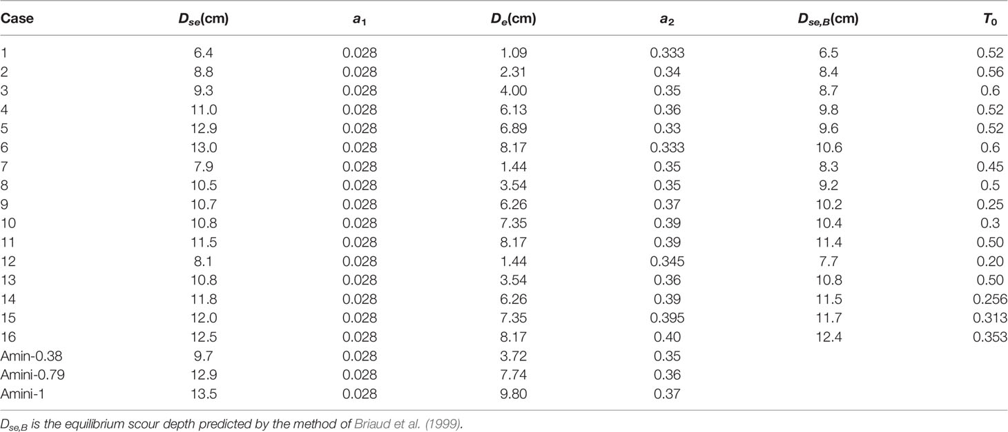
Table 2 Coefficients used in the present work and Amini et al. (2012).
First, the new method (Eq. 25~30) considers the pile spacing, pile arrangement, and aspect ratio, whereas Eq. 31 was originally designed for non-submerged single piles. Second, for a submerged pile, T0 should increase with the increase in pile height because a higher pile results in a larger scour depth and longer time to attain an equilibrium state. However, this trend does not appear in the present work. Finally, Dse fitted by Eq. 31 is occasionally smaller than the scour depth at the end of experiments.
Table 2 shows that for a given velocity intensity, a2 increases with the increase in pile height in the live-bed condition. This can be explained by the relationship between scouring rate and pile height. A larger pile height results in a larger scour depth and a longer time to attain the equilibrium scour stage. An analysis of Eq. 28 reveals that a2 is positively correlated with Kt. Furthermore, De has a negative relationship with Kt. Thus, a2 has a smaller effect on the scouring rate compared with De in the present work because the range of a2 is significantly smaller. Another important conclusion from Table 2 is that a2 increases with the increase in velocity intensity. This implies that a larger velocity intensity results in a higher scouring rate and a shorter time to attain an equilibrium state.
Eq. 32 is derived from the above dimensionless analysis:
A multivariable linear regression method was applied to derive the above relationship (R2 = 0.935). Only live-bed experiment data are displayed here:
4.2.2 Verification of the Proposed Time Factor
Experimental data from the literature are gathered to help improve the above time factor.
4.2.2.1 Clear-Water Local Scour
Experimental data from Amini et al. (2012) and Galan et al. (2018) were used to verify the present method because of the deficiency of long-duration scouring experimental data of submerged pile groups. Only a part of the experimental data of Amini et al. (2012) were considered to verify the above method because only those three experiments have a longer duration (24 h). These are marked as Amin-0.38, Amin-0.79, and Amin-1. Their submerged ratios (H / d) are 0.38, 0.79, and 1, respectively. The coefficients are presented in detail in Table 2. It should be noted that the experiments are conducted in a shallow flow region. Because the ratio of water depth to equivalent pile diameter is d / nDp~2.2 < 3, the water depth would affect the scour depth because the development of the horseshoe vortex is restricted. The temporal developments of submerged pile groups in Amini et al. (2012) are presented in Figure 3. It can be concluded from the fitting curve and experimental data that the pile height affected the scour development in the flow shallowness region. The shallowness effect became significant with the increase in pile height. The proposed method shows the largest deviation for H / Dp = 1 (non-submerged pile groups). Thus, the present work cannot be applied in shallow water flow regions.
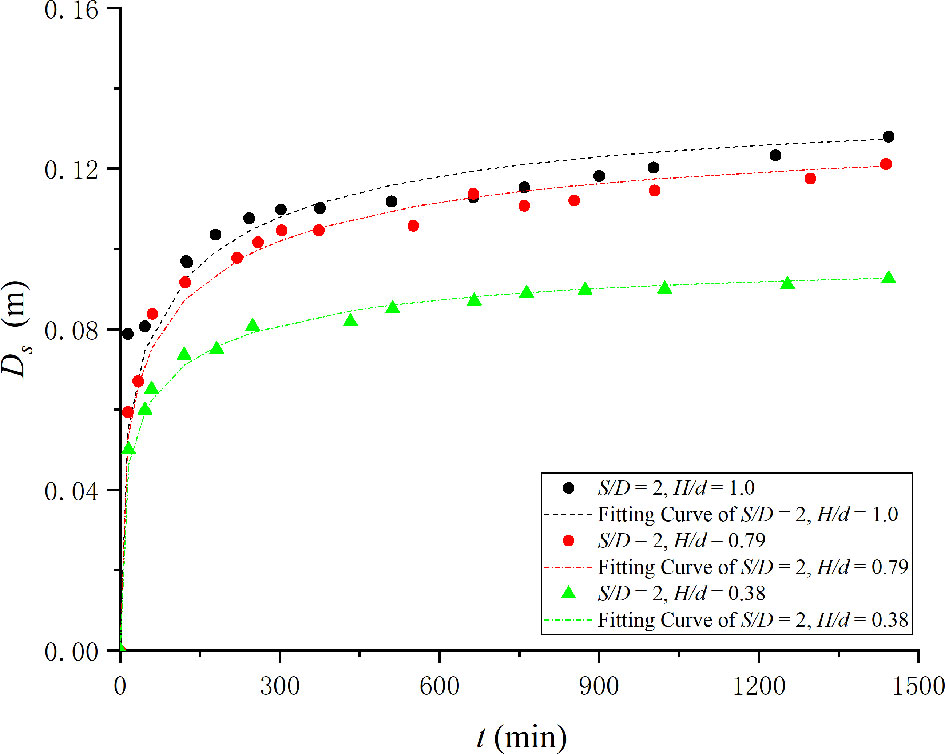
Figure 3 Temporal development of scour in Amini et al. (2012). Experimental data of Galan et al. (2018) were also presented (n = 2) in Table 3 as additional details.
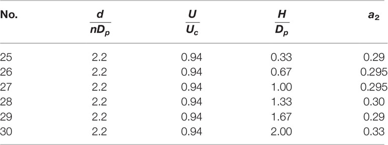
Table 3 Values of a2 in the work of Galan et al. (2018).
The trend wherein a2 increases with the increase in pile height is in accordance with the present work. However, a2 is significantly smaller in the present work. This is owing to the effect of flow shallowness [similar to the work of Amini et al. (2012)]. The horseshoe vortex is restricted by the increase in flow shallowness (decrease in flow depth). This causes the scour rate to decrease. The smaller scour rate also implies a smaller a2.
4.2.2.2 Live-Bed Verification
The data of Yao et al. (2018) were adopted to verify the proposed method because of the deficiency of data on live-bed scour around pile groups. As briefly described in the Introduction, several experiments in Table 1 of Yao et al. (2018) were selected. These include tests 10, 11, 14, 16, and 17. The corresponding values of H / D are 0.6, 0.8, 3, 5, and 7, respectively. The velocity intensity of the selected tests is constant (1.55). The fitted curve and experimental data are plotted in Figure 4.
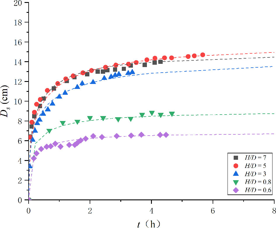
Figure 4 Variation of scouring depth with time (symbols, experimental data of Yao et al. (2018); dashed lines, fitting curve by Eq. 30~31).
It can be concluded from Figure 4 that this new method is effective for submerged pile and submerged pile-group scour in live-bed scour. Thus, the method is effective for submerged structures in both clear-water and live-bed conditions.
4.2.3 Maximum Scour Depth
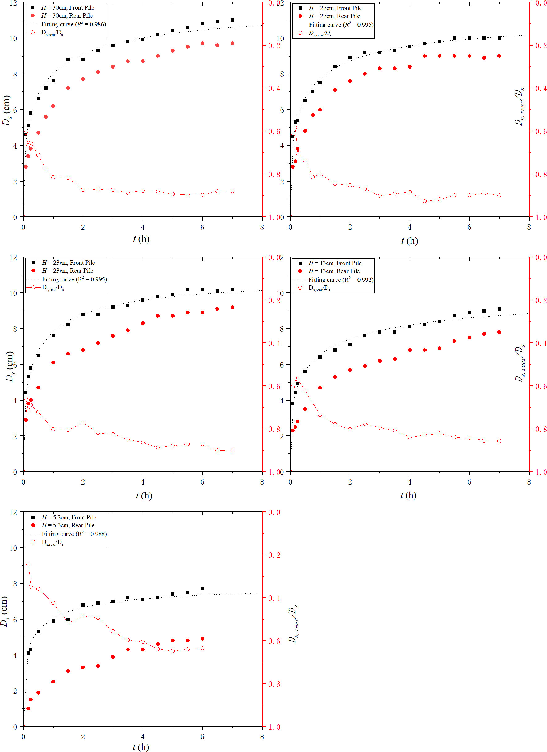
As the new method proposed in the present work displays good performance in both live-bed and clear-water scour, it is adopted as the extrapolation method for the present experiments. The fitting curve of the new method and experimental data are plotted in Figure 5 (U / Uc = 0.98), Figure 6 (U / Uc = 1.09), and Figure 7 (U / Uc = 1.23). In addition, the ratios of the rear pile to the front pile (Ds,rear / Ds) are presented in Figures 6 and 7.
Figures 5–7 show that the scour depth of front piles is larger than that of the rear pile at a given time t for all approaching velocities and pile heights. The ratios of the rear pile to the front pile (Ds,rear / Ds ) reduce with the increase in pile height. The ratios are related to the pile height or velocity intensity. For H = 5.3 cm, this ratio varies rapidly from O(0.9) to O(0.65). This can be attributed to the different scour mechanics. The scour of the front pile results from the reverse pressure gradient and the horseshoe vortex. However, the scour mechanics of the rear pile depends on the pile spacing. In the present work, the pile spacing is 2Dp, which is in the transition region (Sumer and Fredsøe, 2002). With different flow velocities, it may be in alternate reattachment or quasi-steady reattachment. This implies that no horseshoe vortex is formed in front of the rear pile. The scour of the rear pile is dependent completely on the wake shedding of the front pile. The larger height of the front pile results in strong wake shedding and a larger scour depth of the rear pile.
An analysis of Ds,rear / Ds reveals that the front pile first attains the quasi-equilibrium scour stage. Then, the sediment transport weakens, and an inadequate amount of sediments is transported from the front pile. Subsequently, the scour around the rear pile attains its equilibrium scour stage. For the first 15 min, sediment transport is sufficiently strong to cause sheet flow around the front pile. The sediment area is transported with the vortex and then deposited in the rear pile. However, this phenomenon disappears rapidly with the increase of the scour hole of the front pile and a decrease in the scour rate. This phenomenon was also observed by Yang et al. (2021).
It can be concluded from the above information that the marginal delay in the development of the rear pile compared with that of the front pile occurs because the erosive sediments from the front pile are transported to the rear pile and the sheltering effect reduces the erosion from the rear pile. Thus, the sheltering effect and slower development result in a smaller scour depth. The backfilling is attributed to the sediment’s movements.
The scour depth increases with the increase in velocity intensity under the clear-water condition. This is consistent with the trend of single piles (Melville and Sutherland, 1988). However, there is a substantial difference from the phenomena in previous research. The maximum scour depth occurs at the threshold velocity. However, it decreases rapidly when U / Uc = 1.09. This trend reverses again when U / Uc = 1.23. For single piles, the minimum scour depth in live bed generally occurs when U / Uc ~ O(1.3–1.7). This is also different from a research of Yang et al. (2020), wherein the scour depth increased continuously with the velocity intensity in the live-bed condition. It is necessary to recall that the live-bed condition of Yang et al. (2020) is inferred from the experimental conditions.
4.3 Effect of Aspect Ratio
The pile height here is non-dimensional, similar to the aspect ratio. Kh is defined as
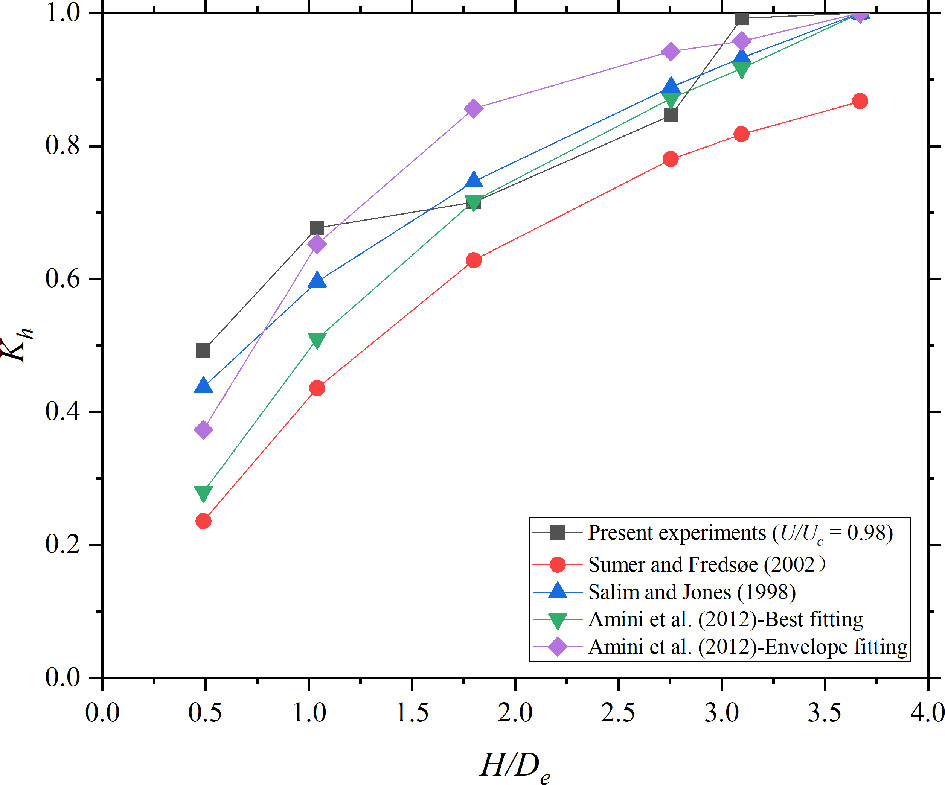
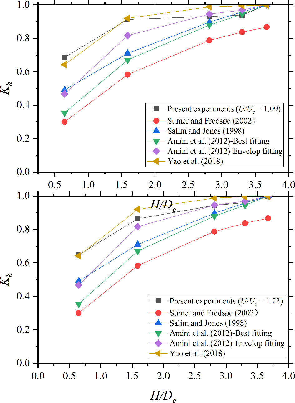
Here, Dse,∞ is the equilibrium scour depth of pile groups with H = 30 cm (non-submerged pile groups). Cases 1–6 (U / Uc = 0.98, clear-water conditions) are plotted in Figure 8. Cases 7–16 (live-bed condition) are plotted in Figure 9.
With regard to scour around pile groups under clear-water conditions, Eq. 6 is considered suitable in this section. However, the experiments of Amini et al. (2012) were conducted in a shallow water region. β is considered to be 1.0.
In the live-bed condition, the experimentally determined Kh is significantly larger than the values in the equations proposed for scour under the clear-water condition. Eq. 8 (Yao et al., 2018) performs better than experimental data because it is determined for live-bed scour without the influence of water depth. Thus, β is related to velocity intensity.
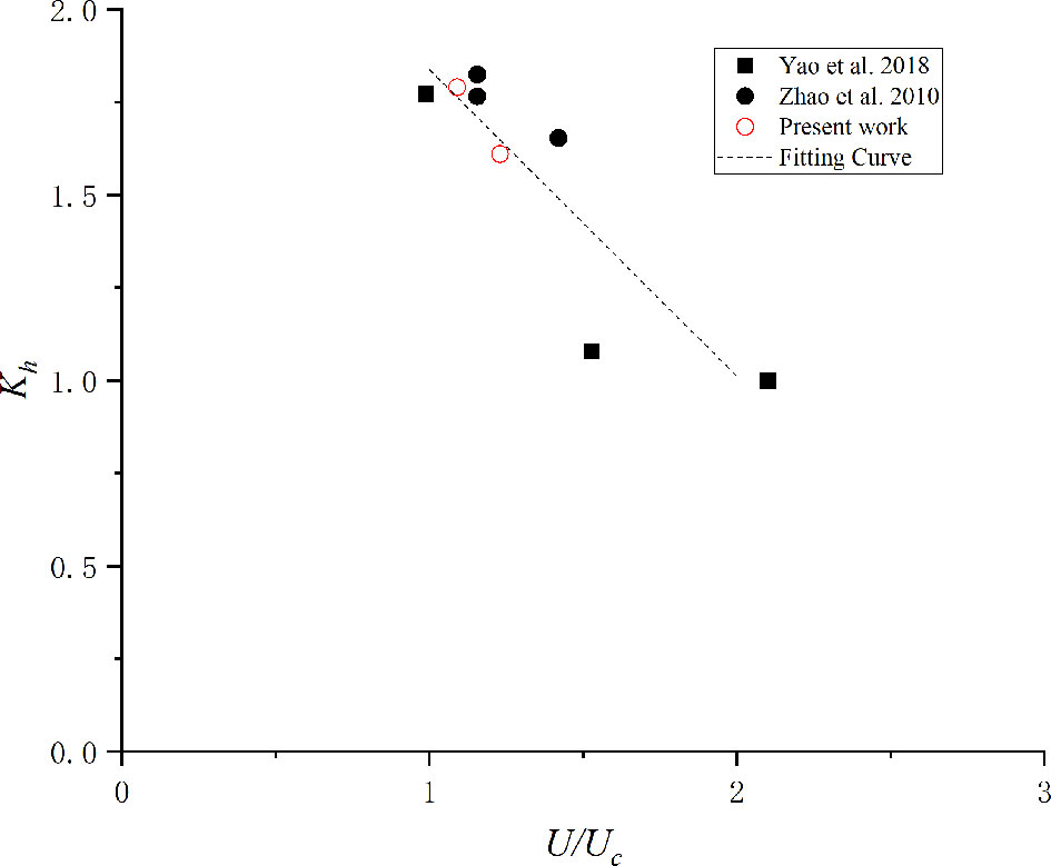
Eq. 35 is derived using the detailed values of Kh in the present work. The experimental data and fitting curve are plotted in Figure 10.
The present fitting has a limitation wherein the velocity intensity should be 1.0 < U / Uc < 2.0. Eq. 35 is suitable for both pier and pile groups. However, it cannot be applied to scour under shallow water flow.
4.4 Scour Area and Scour Volume
Scour depth has been studied as a key scour feature by many research studies. However, the maximum scour depth by itself is insufficient to describe the scour characteristics comprehensively. Scour area and volume have significance in engineering because these can determine the riprapping and dredging workloads. Scour area and scour volume are defined as follows:
The slope angles of the present experiments are in the range of 32°–34°. This is significantly close to the angle of repose determined by experiments. Thus, the slope angle can be considered to be equal to the angle of repose in the present work. This phenomenon has been observed and studied by many researchers (Cheng and Zhao, 2017; Du and Liang, 2019).
Because the slope angle of the present work is equal to the angle of response, the equilibrium scour topography should be similar to the scour topography at the end time. Thus, Ast∝Dst2 and Vst∝Dst3 . The two coefficients KA and KV are the correction factors. Because the equilibrium scour topography is similar to the scour topography at the end time, KA and KV are constant for given velocity intensity and height of pile groups.
Because Ds,end for clear water is less than Dse, the equilibrium scour topography may be not similar to that at the end time. This implies that KA and KV may vary significantly. The calculation method of the present work may cause a large deviation, whereas the Ds,end in the live-bed condition is only marginally less than Dse. It can be considered similar to the scour topography at the end time. Therefore, the methods in the present work are applied only to the live-bed experiments.
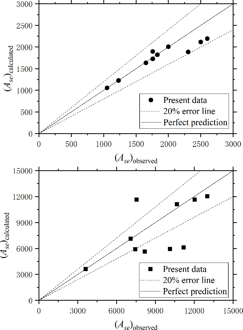
The calculated Ase and Dse are presented in detail in Table 4.
Because angle slopes are constant and equal to the angle of response, θ can be eliminated from Eqs. 21 and 22. These can be removed. KA and VA are functions of velocity intensity and aspect ratio in the present work, respectively.
Assume that KA and VA can be expressed as follows:
With the use of data in Table 4,
where comparisons of measured Ase and Vse with calculated Ase and Vse are presented in Figure 11.
5 Conclusions
The present study focuses on the effect of the aspect ratio and velocity intensity of scour around pile groups. Experiments were conducted in a wide flume, with uniform and cohesionless sand as the bed material. A time factor for both clear-water and live-bed scour around submerged pile groups was determined based on the present experiments. Then, this new time factor is verified by data from the literature, showing a good performance. The scour depth, area, and volume were calculated using this new time factor.
The following conclusions can be drawn from the previous discussion.
A time factor for submerged pile groups is proposed based on the present experiments. It has been verified by experiments in the literature and shows good performance in predicting the equilibrium scour depth for both single pile and pile groups under clear-water and live-bed conditions.
The Dse in the live-bed condition is smaller than the Dse under the threshold velocity intensity in the present work. However, the turning point is significantly smaller than that for a single pile. The turning point is close to 1.1 in the present study.
The Kh in previous studies for submerged structures was corrected, showing that it performs better for scour in the live-bed condition.
Empirical relationships are obtained to predict the equilibrium scour area and volume around submerged pile groups. Both the prediction equations are effective in the present work.
It should be noted that the present conclusion can only be reliable in deep-water regions (d / De> 3). The present time factor is available for U / Uc< 2; more experiments are needed to expand the range of velocity intensity.
Data Availability Statement
The raw data supporting the conclusions of this article will be made available by the authors, without undue reservation.
Author Contributions
BL, ZW, SD, and XP acquired the funding and provided contributions for the design of the work. YL conducted the experiments and wrote the original draft. ZW, BL, and ZY were responsible for the experimental data checksum processing and drawing of figures. All authors contributed to the writing of the revised manuscript and the answers to the reviewer’s comments.
Funding
This study is financially supported by the National Natural Science Foundation of China (Grant Nos. 51739010, 52101338) and Shandong Provincial Key Laboratory of Ocean Engineering (Grant No. kloe202009).
Conflict of Interest
The authors declare that the research was conducted in the absence of any commercial or financial relationships that could be construed as a potential conflict of interest.
Publisher’s Note
All claims expressed in this article are solely those of the authors and do not necessarily represent those of their affiliated organizations, or those of the publisher, the editors and the reviewers. Any product that may be evaluated in this article, or claim that may be made by its manufacturer, is not guaranteed or endorsed by the publisher.
References
Amini A., Melville B. W., Ali T. M., Ghazali A. H. (2012). Clear-Water Local Scour Around Pile Groups in Shallow-Water Flow. J. Hydraulic Eng. 138 (2), 177–185. doi: 10.1061/(asce)hy.1943-7900.0000488
Arneson L., Zevenbergen L., Lagasse P., Clopper P. (2012). Evaluating Scour at Bridges (US: National Highway Institute).
Briaud J.-L., Ting F. C., Chen H., Gudavalli R., Perugu S., Wei G. (1999). SRICOS: Prediction of Scour Rate in Cohesive Soils at Bridge Piers. J. Geotechnical Geoenvironmental Eng. 125 (4), 237–246. doi: 10.1061/(ASCE)1090-0241(1999)125:4(237
Cheng L., An H., Draper S., Luo H., Brown T., White D. “ (2014)UWA's O-Tube Facilities: Physical Modelling of Fluid-Structure-Seabed Interactions”, in: The 8International Conference on Physical Modelling in Geotechnics)
Cheng N.-S., Zhao K. (2017). Difference Between Static and Dynamic Angle of Repose of Uniform Sediment Grains. Int. J. Sediment Res. 32 (2), 149–154. doi: 10.1016/j.ijsrc.2016.09.001
Dey S., Raikar R. V., Roy A. (2008). Scour at Submerged Cylindrical Obstacles Under Steady Flow. J. Hydraulic Eng. 134 (1), 105–109. doi: 10.1061/(asce)0733-9429(2008)134:1(105
Du S., Liang B. (2019). Comparisons of Local Scouring for Submerged Square and Circular Cross-Section Piles in Steady Currents. Water 11 (9), 1820–1833. doi: 10.3390/w11091820
Ettema R., Melville B. W., Barkdoll B. (1998). Scale Effect in Pier-Scour Experiments. J. Hydraulic Eng. 124 (6), 639–642. doi: 10.1061/(asce)0733-9429(1998)124:6(639
Franzetti S., Larcan E., Mignosa P. (1982). “Influence of Tests Duration on the Evaluation of Ultimate Scour Around Circular Piers,” in Int. Conf. On the Hydraulic Modeling of Civil Engineering Structures. (Bedford, England: BHRA Fluid Engineering), 381–396.
Fazeres-Ferradosa T., Taveira-Pinto F., Rosa-Santos P., Chambel J. (2019). Probabilistic Comparison of Static and Dynamic Failure Criteria of Scour Protections. J. Mar. Sci. Eng.7 (11), 400.
Fazeres-Ferradosa T., Chambel J., Taveira-Pinto F., Rosa-Santos P., Taveira-Pinto F. V. C., Giannini G. (2021). Scour Protections for Offshore Foundations of Marine Energy Harvesting Technologies: A Review. J. Mar. Sci. Eng. 9(3), 297.
Galan A., Simarro G., Fael C., Cardoso A. H. (2018). Clear-Water Scour at Submerged Pile Groups. Int. J. River Basin Manage. 17 (1), 101–108. doi: 10.1080/15715124.2018.1446964
Lança R., Fael C., Maia R., Pêgo J. P., Cardoso A. H. (2013). Clear-Water Scour at Pile Groups. J. Hydraulic Eng. 139 (10), 1089–1098. doi: 10.1061/(asce)hy.1943-7900.0000770
Larsen B. E., Fuhrman D. R., Baykal C., Sumer B. M. (2017). Tsunami-Induced Scour Around Monopile Foundations. Coastal Eng. 129, 36–49. doi: 10.1016/j.coastaleng.2017.08.002
Melville B. W. (1984). Live-Bed Scour at Bridge Piers. J. Hydraulic Eng. 110 (9), 1234–1247. doi: 10.1061/(asce)0733-9429(1984)110:9(1234
Melville B. W. (1997). Pier and Abutment Scour: Integrated Approach. J. Hydraulic Eng. 123 (2), 125–136. doi: 10.1061/(ASCE)0733-9429(1997)123:2(125
Melville B. W., Chiew Y.-M. (1999). Time Scale for Local Scour at Bridge Piers. J. Hydraulic Eng. 125 (1), 59–65. doi: 10.1061/(asce)0733-9429(1999)125:1(59
Melville B. W., Chiew Y.-M. (2000). Time Scale for Local Scour at Bridge Piers. J. Hydraulic Eng. 125 (1), 59–65. doi: 10.1061/(ASCE)0733-9429(2000)126:10(793.2
Melville B. W., Coleman S. E. (2000). Bridge Scour (Colorado, United States:Water Resources Publication).
Melville B. W., Sutherland A. J. (1988). Design Method for Local Scour at Bridge Piers. J. Hydraulic Eng. 114 (10), 1210–1226. doi: 10.1061/(asce)0733-9429(1988)114:10(1210
Raudkivi A. J., Ettema R. (1983). Clear-Water Scour at Cylindrical Piers. J. Hydraulic Eng. 109 (3), 338–350. doi: 10.1061/(asce)0733-9429(1983)109:3(338
Richardson E. V., Davis S. R. (2001). Evaluating Scour at Bridges. (Washington, DC, USA: United States. Federal Highway Administration. Office of Bridge Technology; National Highway Institute)
Salim J., Jones J. S. (1996). “Scour Around Exposed Pile Foundations,” in North American Water and Environment Congress & Destructive Water (ASCE), 2202–2211.
Sheppard D. M., Glasser T. (2004) “Sediment Scour at Piers With Complex Geometries”. in Proc., 2004 2nd Int. Conf. on Scour and Ero-sion., November 14.–17 (Singapore: World Scientific).
Sheppard D. M., Miller W. (2006). Live-Bed Local Pier Scour Experiments. J. Hydraulic Eng. 132 (7), 635–642. doi: 10.1061/(asce)0733-9429(2006)132:7(635
Sheppard D. M., Odeh M., Glasser T. (2004). Large Scale Clear-Water Local Pier Scour Experiments. J. Hydraulic Eng. 130 (10), 957–963. doi: 10.1061/(asce)0733-9429(2004)130:10(957
Sheppard D., Renna R. (2005). Bridge Scour Manual. (Tallahassee, Florida: Florida Department of Transportation).
Sumer B. M., Fredsøe J. (2002). The Mechanics of Scour in the Marine Environment (Singapore:World Scientific Publishing Company).
Wu M., De Vos L., Arboleda Chavez C. E., Stratigaki V., Fazeres-Ferradosa T., Rosa-Santos P., et al. (2002). Large Scale Experimental Study of the Scour Protection Damage Around a Monopile Foundation Under Combined Wave and Current Conditions. J. Mar. Sci. Eng. 8 (6), 417.
Yang Y., Qi M., Wang X., Li J. (2020). Experimental Study of Scour Around Pile Groups in Steady Flows. Ocean Eng. 195, 106651–106662. doi: 10.1016/J.OCEANENG.2019.106651
Yang F., Qu L., Zhang Q., Tang G., Liang B. (2021). Local Scour Around Tandem Square Porous Piles in Steady Current. Ocean Eng. 236, 109554–109569. doi: 10.1016/j.oceaneng.2021.109554
Yao W., An H., Draper S., Cheng L., Harris J. M. (2018). Experimental Investigation of Local Scour Around Submerged Piles in Steady Current. Coastal Eng. 142, 27–41. doi: 10.1016/j.coastaleng.2018.08.015
Zhao M., Cheng L., Zang Z. (2010). Experimental and Numerical Investigation of Local Scour Around a Submerged Vertical Circular Cylinder in Steady Currents. Coastal Eng. 57 (8), 709–721. doi: 10.1016/j.coastaleng.2010.03.002
Keywords: submerged pile groups, local scour, time factor, aspect ratio, velocity intensity
Citation: Lu Y, Wang Z, Yin Z, Du S, Pan X and Liang B (2022) Experimental Study on Aspect Ratio and Velocity Intensity of Scour Around Submerged Pile Groups. Front. Mar. Sci. 9:910723. doi: 10.3389/fmars.2022.910723
Received: 01 April 2022; Accepted: 29 April 2022;
Published: 01 June 2022.
Edited by:
Zeng Zhou, Hohai University, ChinaReviewed by:
Liqin Zuo, Nanjing Hydraulic Research Institute, ChinaFrancisco Taveira-Pinto, University of Porto, Portugal
Copyright © 2022 Lu, Wang, Yin, Du, Pan and Liang. This is an open-access article distributed under the terms of the Creative Commons Attribution License (CC BY). The use, distribution or reproduction in other forums is permitted, provided the original author(s) and the copyright owner(s) are credited and that the original publication in this journal is cited, in accordance with accepted academic practice. No use, distribution or reproduction is permitted which does not comply with these terms.
*Correspondence: Zhenlu Wang, d2FuZ3poZW5sdUBvdWMuZWR1LmNu
 Youxiang Lu
 Zhenlu Wang
 Zegao Yin1,2