 Tao Zou
 Xinbo Niu1
 Longbin Tao
- 1School of Naval Architecture and Ocean Engineering, Jiangsu University of Science and Technology, Zhenjiang, China
- 2Department of Naval Architecture, Ocean and Marine Engineering, University of Strathclyde, Glasgow, United Kingdom
During the massive manufactures and installations of fixed offshore wind turbines in China, initial imperfections were often found in the inspection. As more and more attentions and efforts of the wind energy sector have been devoted to deep waters with fixed and floating wind turbines (FWTs), the impact of such initial imperfections on fatigue assessment is paramount to the reliable design and safe operation, which warrant rigorous study. This paper presents a comprehensive review of three different initial imperfections and their impacts on the fatigue lifetime of FWTs’ tower flange connections. A brief introduction on FWTs and flange connections is provided at first. This is followed by a detailed discussion of the environmental loadings and fatigue assessment on the flange bolted connections. Finally, a comprehensive review of the state-of-art research on three common initial imperfections, including flatness divergence, bolt loosening and tower inclination, are presented. Their impact on fatigue assessment is further discussed.
1 Introduction
Offshore wind power industry in China is growing rapidly to pursue a net-zero future. In 2021, the capacity of Chinese offshore wind power increased by 16.9 gigawatt, more than any other country’s increase. All these offshore wind turbines (OWTs) are fixed in shallow waters. With such a rapid expansion, the potential of shallow water wind power is nearly exhausted. The offshore wind energy sector has been increasingly focusing on the relatively deep water with floating wind turbines (FWTs).
Different from fixed OWTs, FWTs are restrained by various mooring systems typically undergo displacement in six degrees-of-freedom. They are subjected to wind, wave and current environmental loadings. The wave load is directly acting on the foundations or supporting structures. The upper structure is vulnerable to wind load and dynamic loading from blades’ rotations. The intermediate towers connect the upper structure and foundations, which are often subjected to multiple cyclic loadings from different sources. Hence, it has been often reported on fatigue damage in the tower of an operating wind turbine (Zou et al., 2021; Gao et al., 2022; Zheng and Chen, 2022; Wang et al., 2022).
To assess the fatigue damage on FWTs, Kvitten and Moan (Kvittem and Moan, 2015) presented a set of time-domain analysis procedures. An aero-hydro-servo-elastic tool FAST was used to simulate the global response of FWTs. The authors investigated the effect of simulation duration, number of random realisations and bin sizes to obtain the distribution of cyclic hot spot stress over the tower sections. Luan et al. (Fang et al., 2020; Fang et al., 2021) developed Kvitten’s approach and extended its capabilities to determine the global forces and moments in FWTs’ components through a beam element model. The result of Luan’s approach can output the time-series of stress over tower sections, which is the boundary conditions for following local model (flange connections) analysis. Xu et al. (Xu et al., 2019; Xu et al., 2019) upgraded Kevitten’s approach with fully nonlinear wave theory to investigate the effect of wave nonlinearity on FWTs’ fatigue damage and extreme response. They concluded that effect of wave nonlinearity is significant for FWTs’ surge motions and not sensitive to tower base bending moments.
During the large number of OWTs’ installations in China, a lot of imperfect geometric conditions are found in the wind turbines’ towers. Due to improper manufactures and installations, different initial imperfections may occur and undermine the fatigue strength of wind towers, see Figure 1. To improve the design of FWTs in the future exploitation of deep waters, the impact of initial imperfections on the fatigue assessment of FWTs’ towers should be clarified.
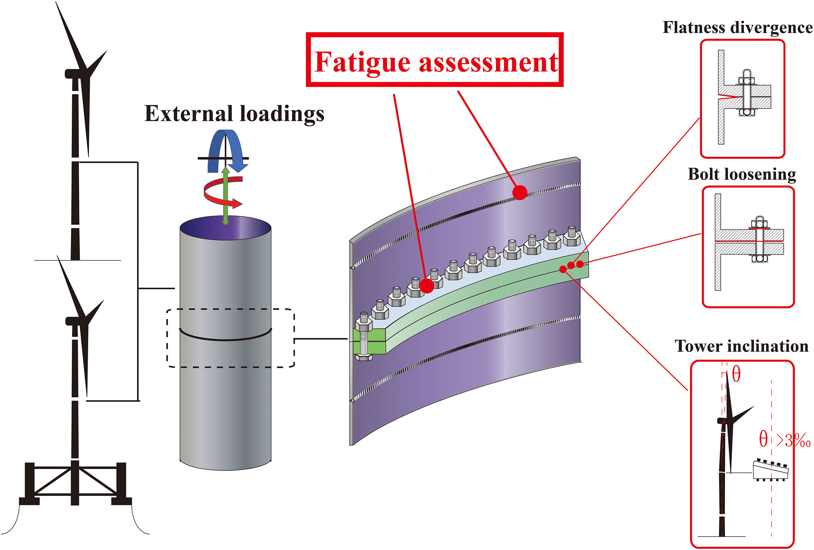
Figure 1 Initial imperfections in offshore wind turbines.
2 Floating wind turbines and flanges
The components of FWTs include upper structure (rotor-nacelle assembly), substructure (tower and foundation) and mooring system. In the past decades, significant research focused on the global response simulations of FWTs (Dong et al., 2012; Kvittem and Moan, 2015; Luan et al., 2017; Luan et al., 2018; Xu et al., 2019), as it is the foundation for any other further analysis. It is still challenging to simulate the global motion of FWTs accurately, because FWTs are flexible and subjected to wind, wave and current simultaneously, which makes FWTs’ motions rather complex. Hence, an aero-hydro-servo-elastic analysis is required to simulate the coupled effect of environmental loadings on the structural motions. Many numerical programs have been developed to simulate the global response of FWTs, as listed in Table 1.
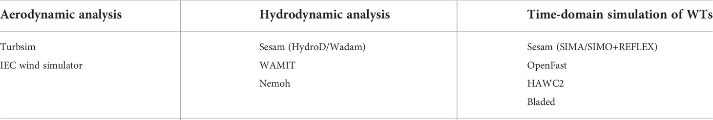
Table 1 Numerical programs for the analysis of floating wind turbines’ global response.
Wind turbine failure is often due to the failure of rotor blades or of the steel tower (Márquez et al., 2016).Wind turbines’ towers are typically manufactured in steel segments with bolted flange connections. Due to the stress concentration around the flange, many fatigue cracks have been found around the flange connections of the inland wind turbines, see Figure 2. Offshore FWTs suffer from more severe environmental loadings, thus more attentions should be paid on their design of flange connections (Mehmanparast et al., 2020).
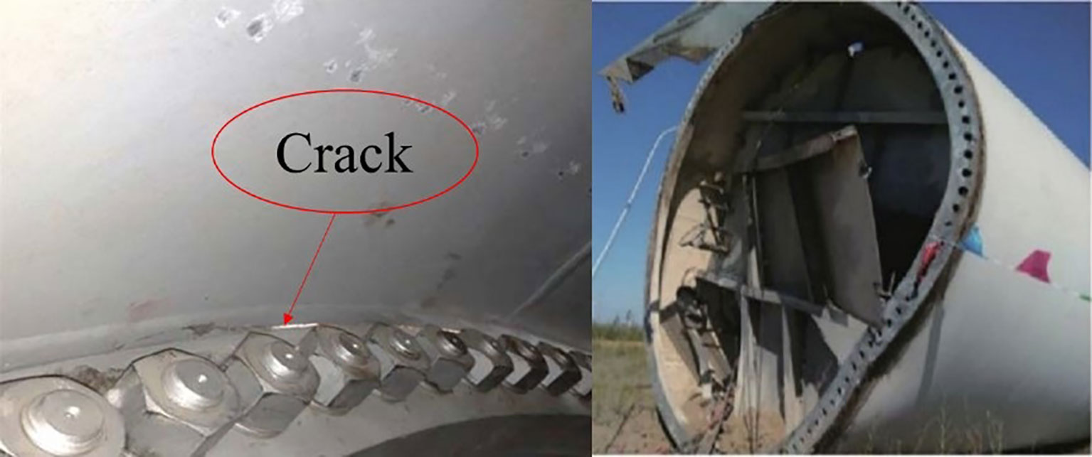
Figure 2 Fatigue cracks and fatigue failures of inland wind turbine towers (Zou et al., 2021).
The conventional bolted flanges are L-shaped, as seen in Figure 3. Researchers have extensively investigated the stiffness and mechanical resisting capacities of conventional L-shape flanges (Seidel, 2001; Heistermann et al., 2009; Schwingshackl and Petrov, 2012; Van-Long et al., 2013; Wang et al., 2013). When wind turbines are installed increasingly from shallow water into deep water, the thickness and diameter of wind turbine towers are also increasing to support larger rotors and nacelles accordingly. Another type of flanges are Reverse Balanced (RB) flanges, see Figure 3. The RB flange connections consist of flange plates, stiffening plates, and high–strength blots. Compared to the conventional bolted flanges, RB flanges have advantages such as higher stiffness and lower cost (He et al., 2016).
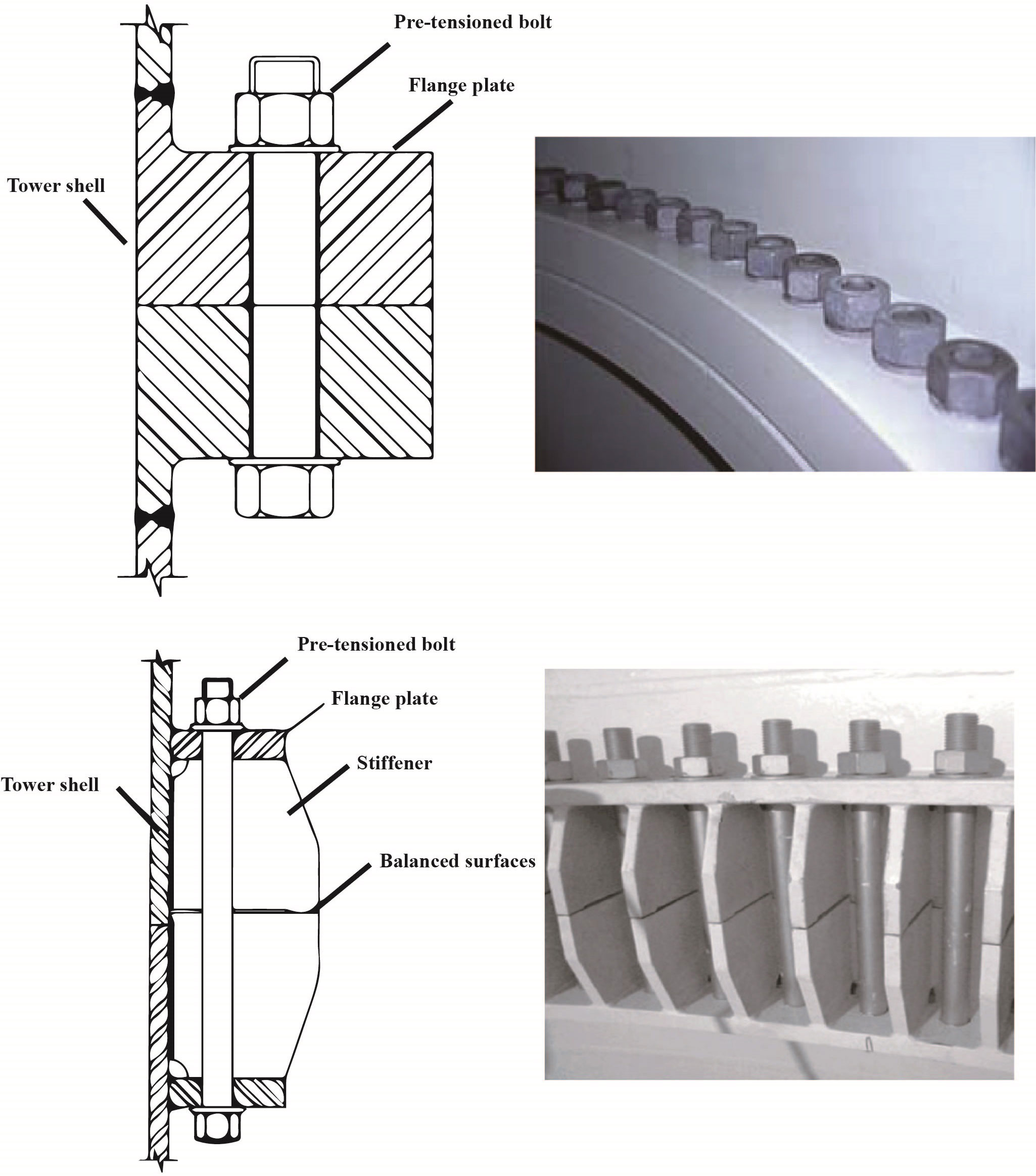
Figure 3 Configurations of L-shape flanges (up) and reverse balanced flanges (down) (He et al., 2016; Alonso-Martinez et al., 2019) description of environmental conditions.
During manufactures and installations, imperfect geometric flange connections may occur which can lead to initial imperfections such as flatness divergence or tower inclinations. In addition, the bolt loosening may also undermine the fatigue strength of flange connections. The details of these initial imperfections and their impacts on fatigue damage are discussed in Section 7.
The design of offshore wind turbines requires both functionality and safety. For safety purpose, the OWTs should be strong enough under ultimate limit states (ULS), fatigue limit states (FLS) and accidental limit states (ALS). Among them, FLS is especially important for FWTs, because the system is subjected to millions of cycles of dynamic loads during the whole service life of FWTs.
According to the experience from inland wind turbine, many wind turbine collapse cases are due to the fatigue damage on cylinder tower and flanges (Alonso-Martinez et al., 2019). In order to ensure the safety of OWTs, the environmental loads, including wind, wave and current, should be clarified first (Hu et al., 2020). All these environmental loads induce aerodynamic and hydrodynamic impacts on the structures.
2.1 Wind
The description of wind can be divided into two parts: spatial part and temporal part, as seen in Equation (1)
where us(x,y,z) denotes the mean wind speed spatial variation, and [u1(x,y,z,t), u2(x,y,z,t), u3(x,y,z,t)]. stands for the temporal variation. The spatial mean wind speed variation is usually described by wind shears, and the temporal variation is represented by wind turbulence in vertical, longitudinal and lateral directions. In addition, the temporal variation can also be represented by frequency spectrum models such as Kaimal or Mann models. The temporal variation is described as stationary or non-stationary depending on the time scales. In practice, a short-term wind condition with 10 minutes period is assumed as stationary.
For OWTs, wind conditions are the primary external environmental conditions, while the wave and current conditions may also play a role. The aerodynamic loads are dependent (among other factors) upon the rotational speed of the rotor, the average wind speed across the rotor plane, the three-dimensional turbulence intensity, the wind shear, wind direction changes, the density of the air, the aerodynamic shapes of the wind turbine components and their interactive effects, including the aeroelastic effects (DNVGL (2016a)). According to the blade element momentum theory, wind blows over airfoil and generates lift force and drag force. These forces rotate the blades and push the wind tower structure in horizontal direction, which eventually results in torque and thrust acting on the wind tower. The other loads acting on the wind tower include the wind-induced pressure, the eccentric moment from the gravity of nacelle and blades. The OC3 baseline 5 MW NREL offshore wind turbine is exemplified here with rated wind speed 11.4 m/s, rotor diameter 126m, mean torque 2500 KN• m and mean thrust 300KN (Goupee et al., 2017).
2.2 Wave
The distribution of ocean waves is usually described by wave spectra. Depending on the location and the sea state, wave spectra contain substantial energy mainly in the range from 5 to 25 seconds. For a FWT, the natural periods of motion should be designed to avoid resonance. The natural period in heave is normally above 25 second for a spar and below 5 second for a tension leg platform. The short-term wave conditions are usually described as stationary with 1-3 hours, and they are characterized by wave height and wave period. For instance, JONSWAP spectrum is used to describe its frequency distribution of wave energy for fetch-limited seas; Pierson-Moskowitz (PM) spectrum is for fully developed seas. Sometimes, a two peak spectrum is used to describe combined seas with wind wave and swell. To simplify the calculations, a linear wave assumption is often applied, but the nonlinear effect of wave is getting more and more attentions these years (Xu et al., 2019; Xu et al., 2019). Stationarity of wave conditions is usually assumed for 1-3 hours.
The hydrodynamic forces on slender structures are usually calculated based on Morison’s formula, which is a semi-empirical formulation to capture the wave force on a fixed or floating offshore structures. It’s composed of three terms to stand for inertia force, drag force and added mass force induced by the structures’ acceleration in water. For large volume structures, linear potential theory is recommended to calculate the diffraction and radiation forces. Computational Fluid Dynamics (CFD) approach is utilized to mathematically model a physical-fluid-flow related phenomenon (Gao et al., 2020; Gao et al., 2021). CFD approach is used to solve strongly nonlinear problems. It has the highest accuracy if properly verified and validated but can be computational expensive.
Current may also affect the FWT’s motions especially on supporting structures of extensive draft, but it mainly acts on the mooring systems and contributes less to fatigue damage on the towers. Therefore, current force is not discussed here.
3 Fatigue assessment
Fatigue damage is a cumulative process and it requires long-term sea condition data to predict. Unlike structural failures due to insufficient ultimate strength, fatigue failures usually attribute to moderate sea conditions, because the occurrence of moderate sea conditions is much higher than that of extreme conditions. The long-term sea conditions are usually represented either by a long-term distribution of several sea state related parameters or the sum of short-term sea conditions. A structure’s fatigue design should ensure that its fatigue strength can resist all these wave conditions in the operation stage. However, initial imperfections may introduce stress concentration and undermine the fatigue strength of flange connections. They should be considered in the design stage.
3.1 S-N curve based approach
For offshore structures’ design, fatigue damage is usually calculated based on the S-N curve approach. The fatigue resistance is represented by S-N curves. If the long-term stress range distribution is defined as the sum of the Rayleigh distribution of each short-term stress range corresponding to each sea state, the cumulative fatigue damage with one slope S-N curve is given by:
where D is accumulated fatigue damage, ω0.is the average long-term zero-crossing frequency, a and m are the S-N curve parameters, Td is the design life of offshore structures Γ is gamma function, Nload is total number of load conditions, pn is the fraction of design life in load condition n, rijn is relative number of stress cycles in short-term condition i,j, m0ijnthe zero spectral moment of stress response process.
The stress response spectrum and spectral moments in linear models are defined as
where Hσ(ω|θ) is the transfer function representing the relation between unit wave amplitude and response, Sn(ω|Hs,Tz) is wave spectrum, f(θ) is the wave spreading function. It can be seen that, for a particular offshore structure, the fatigue damage is mainly determined by sea states which are represented by wave scatter diagrams, as seen in Table 2. The blocks with dark color background contribute most to the fatigue damage, because they have much higher frequency of occurrences.
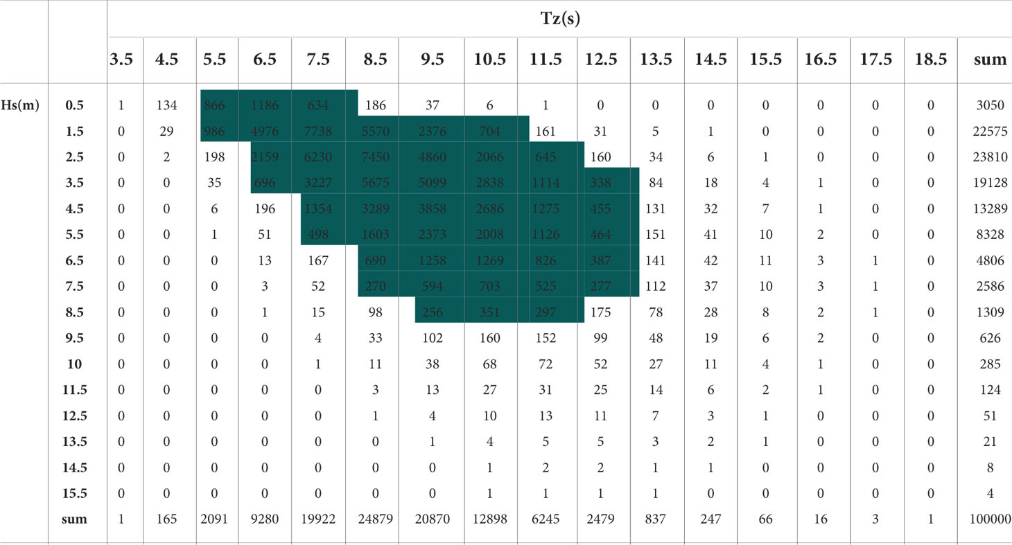
Table 2 The wave scatter diagram.
3.2 Full long-term analysis
As discussed in section 3.2, wave loadings are the primary source of fatigue damage for offshore structures. In design stage, it is highly recommended to identify all the wave conditions which the offshore structures will encounter in their service life.
Wave scatter diagram combines all effective short-term extreme response distribution associated with their corresponding probability of occurrence. Each block is defined as the statistical description of wave conditions over 3 or 6 hours with its significant wave height (Hs), zero crossing period (Tz) and occurrence. The sea states in scatter diagrams are characterized based on observations, measurements or hindcast. Then, the fatigue damage in each short-term sea state is calculated, and the long-term fatigue damage is accumulated by the summation of all short-term fatigue damages.
3.3 Global-local methodology
In this section, a global-local methodology of the fatigue calculation procedure is described, emphasizing the theoretical concepts associated with the modal superposition and fatigue methods. A general workflow for the global-local fatigue assessment methodology is suggested in Figure 4, introducing two different phases of analysis that follow an increasing detail of geometrical, material and contact properties as the assessment progresses from the global to the local scale. The two fatigue analysis phases are systematized as follows. In the first phase, a global approach based on the accumulation of damage computed with nominal stresses and S-N curves is introduced. The adopted global numerical model should be accurate enough to obtain nominal stresses to be used as input loading for the linear damage accumulation method. Nonetheless, the available S-N curves with nominal stress may not properly reflect the local geometrical and material characteristics of critical details, and conservative assessment for the fatigue resistance may be considered. Based on this fatigue analysis result, the critical details should be identified which require a more refined assessment by implementing local scale models. Then, in the second phase, submodelling techniques leveraged by modal superposition concepts are used to evaluate accurately local fatigue damage. Hot spot stress and notch stress concepts are proposed to consider more geometrical and local surfaces details (Horas et al., 2022).
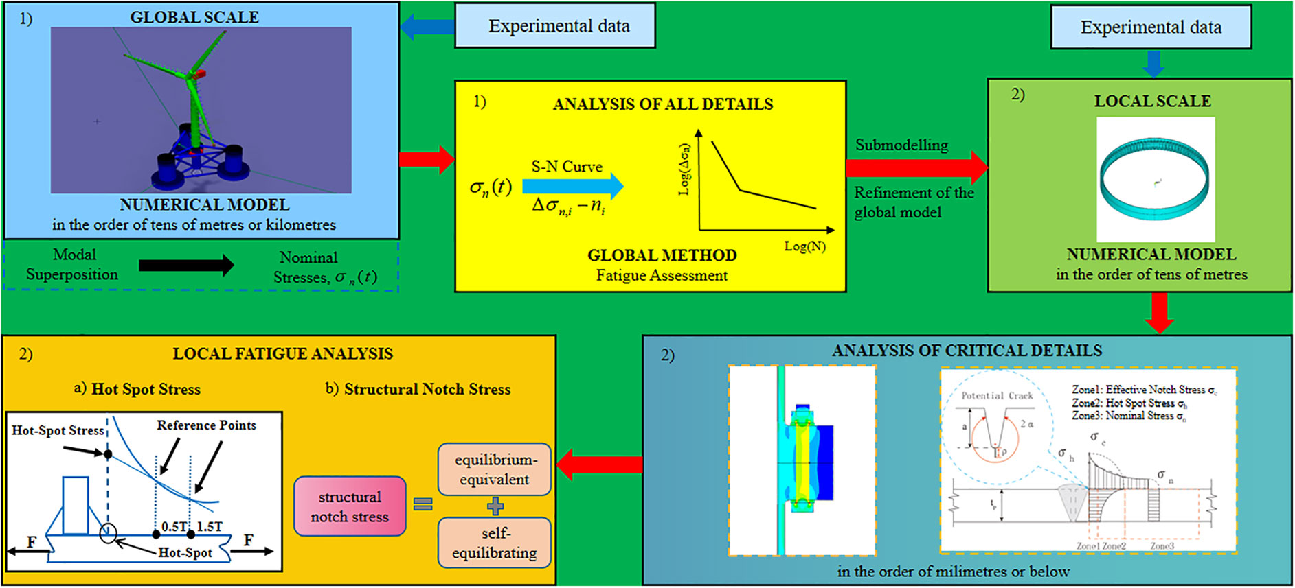
Figure 4 Workflow of the global-local fatigue assessment methodology for offshore wind turbines.
4 External loadings on flange bolted connections
According to the section above, wind towers are subjected to various external dynamic and constant loadings. Some of them are acting directly on the wind tower, the rest are acting on nacelles, blades and substructures. For fatigue assessment of flange bolted connections, the sensitive areas, where high geometric stress concentration occurs, should be clarified first. There are basically two types of sensitive area in the tower: bolts and welding seams. The local structure of flange bolted connections and sensitive areas are shown in Figure 1. The external loadings over the tower cross section are classified as follows:
1. The torque induced x-axis moments Mx
2. The wind thrust induced y-axis moments My1
3. The wind pressure induced y-axis moments My2
4. The wind induced shear S1
5. The by the eccentric gravity of upper structure (rotor and nacelle) G1 and its induced y-axis moments My3
6. The gravity of tower itself G2
7. The FWT’s motion induced inertia forces F(i)
In short, the flange connections are mainly subjected to moments, pressure and shear. The axial stress over the tower cross section was calculated according to Equation (5). The shear is neglected due to its minor contribution to fatigue damage.
My3 and gravity loadings are considered as constant loadings. They do not affect the stress range over the cross section, but may still play a role in fatigue assessment by increasing or decreasing the mean stress. For FWTs, the motion induced inertia forces should be considered.
As FWTs’ substructures are not fixed to the seabed, they have oscillating motions in six degrees of freedom (DOFs). The substructure’s motions may influence the aerodynamic condition of rotor, which makes the aerodynamic loadings on FWTs much more complicated than those on fixed wind turbines. Mostafa et al. (Nihei et al., 2012) studied the interactions between the rotary motion of the wind turbine blade and the dynamic motion of the Spar type FWT through both numerical simulations and experiments. Among all motions in DOFs, surge and pitch are regarded as the most important ones affecting the FWTs’ aerodynamics (Bayati et al., 2016; Fang et al., 2020; Fang et al., 2021). Once the aerodynamic conditions are affected by the substructures’ motions, the external forces on the wind tower, such as Mx and My1, are also changed. Hence, it is necessary to consider the impact of FWTs’ motions in the fatigue assessment. This impact is further discussed in section 7.3.
5 Numerical model of flange connections
The research on fatigue assessment for wind turbine towers requires experiments (Shirani and Härkegård, 2011a; Shirani and Härkegård, 2011b; Van-Long et al., 2013; Schaumann and Eichstädt, 2015; Oechsner et al., 2015) or on-site measurements (Pollino and Huckelbridge, 2012; Benedetti et al., 2013). However, due to the limit of these measured data, numerical modelling is more widely used to analyze the fatigue life of local flange connections. In a numerical model of large flange connections, the fatigue strength involves many factors which should be considered (Sutherland, 1999; Ding and Chen, 2013; Do et al., 2015; Do et al., 2015; Ragan and Manuel, 2016; Blachowski and Gutkowski, 2016). The large size of flange connections in OWTs means large dimensions, large number of bolts and more complex interactions, which makes more uncertainties in modellings (Redondo and Mehmanparast, 2020). Hobbs et al. (Hobbs, 2000) have investigated the fatigue strength of M12 high tensile bolts. Their study revealed that bolted joints’ fatigue strength is highly related to the stiffness level of joints and the preload level. Couchaux et al. (2017) pointed out that secondary forces are induced in bolts by the contact stress between flange parts.
The finite element method (FEM) is a recommended approach to analyze the stress distribution around flange connections, as shown in Figure 5. To simplify the modelling and minimize the computational cost, one or a half flange segment of interest is usually generated through ANSYS, ABAQUS or other FEM software. There are three key issues in the FEM modellings: element selection and mesh, external load and boundary conditions, preload and fiction between contact surfaces.
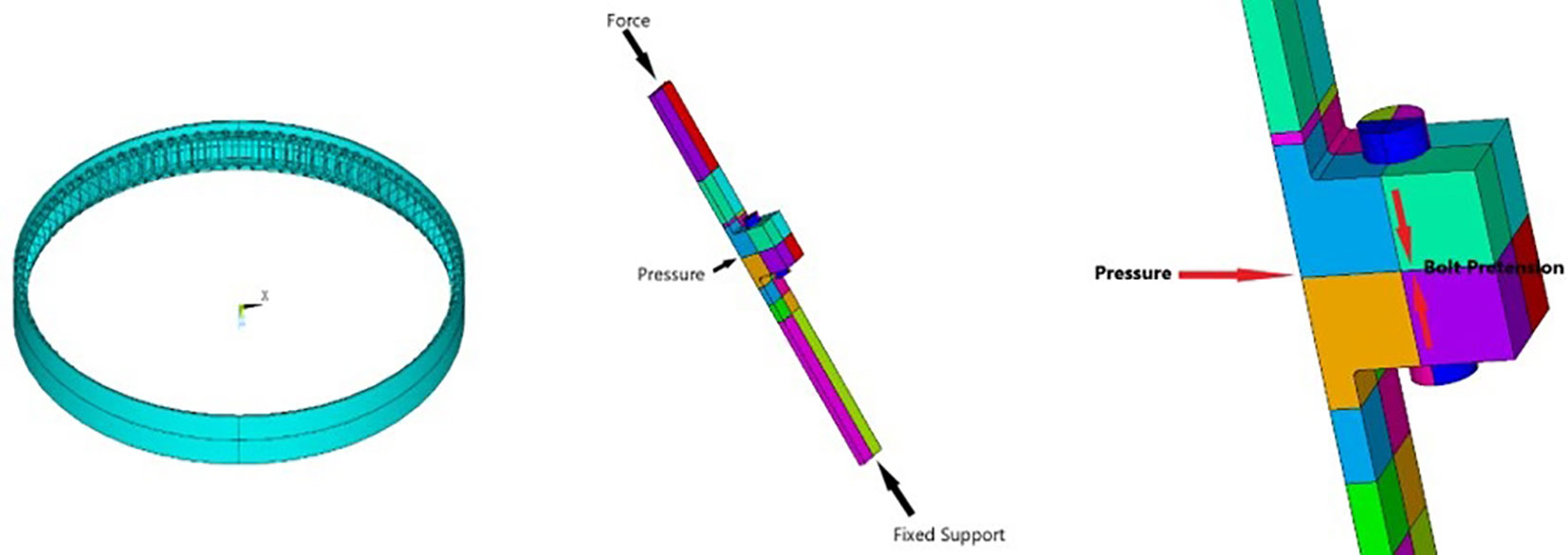
Figure 5 Finite element model of ring shape flanges (left); local model of flanges and its boundary conditions (right).
A finite element model should not only have a low computational requirement but reflect the key characteristics such as irregular geometries and large deformations. Finite elements with more nodes, for example SOLID95 in ANSYS, are often recommended to model the structural parts with irregular geometries or large deformations; finite elements with less nodes, for example SHELL93 in ANSYS, for other parts. Besides, a pretension element is used to apply preload on the bolts. As for meshing, a small mesh size is used to mesh the areas with high stress concentration; while relatively large mesh size is adopted for the other areas.
In the fatigue assessment of wind tower, cyclic loadings on the tower shell sections are simulated by the global simulations and transferred as the boundary conditions for the local model simulation. Then, a local model of flange is required to obtain the stress time series at the sensitive locations. A load transfer function (LTF) is usually used to calculate the cyclic loadings at the bolts or welding seams based on the boundary conditions.
The FE model is under compression or tension depending on where this segment located around the ring flange. The lower surface of tower shell is usually fixed as the boundary condition. The whole tower shell also suffers from wind load, and a preloading force is applied on the bolt and flange. All these loads are shown in Figure 5.
The preload on the pretension elements connects the upper and lower parts of flanges together. DNVGL ST-0126 and DNVGL-OS-C101 have suggested the requirements for the bolt preloading (DNVGL (2018); DNVGL (2016b)).
where:
Fp = preloading force
fub = ultimate tensile strength of bolt material
As = stress area of bolt
However, there are many uncertainties exist in the preloading forces during the installation stage. Attention should also be paid on the self-loosening effect, which will be further discussed in Section 7.2. The contact surface between the flange parts is set as frictional; and the contacts between the bolts and flanges are often defined as either frictional (Alonso-Martinez et al., 2019; Weijtjens et al., 2021) or bonded (Badrkhani Ajaei and Soyoz, 2020), see Figure 6. The frictional contacts are defined with frictional coefficients µ Ajaei and Soyoz recommended a value of the frictional coefficient between two flange parts as 0.45 according to DNV-OS-C101 (DNVGL (2016b)). Gorst et al. (Weijtjens et al., 2021) suggested µ=0.25 for contacts between washers and flange surfaces.
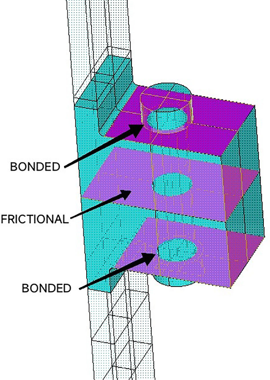
Figure 6 Contact surfaces in a local flange.
6 Initial imperfection
Flange imperfections have a significant influence on the LTF (Weijtjens et al., 2021). Since the design criterion of FWTs is higher than that of fixed wind turbines, it is necessary to pay more attention on the occurrence of initial imperfections during the manufacture and installation of FWTs. China’s offshore industry has manufactured and installed significant number of offshore wind turbines during recent years. Among them, it is reported that three types of initial imperfections are most common to occur. They are flatness divergence, bolt loosening and tower inclination.
6.1 Flatness divergence
Under perfect geometric conditions, as the surface pressure between the two flange parts increases due to the tightening, a clamp force emerges centrically around the longitudinal bolt axis as a counterpart of the preload, as shown in Figure 7. With the clamp force distributed symmetrically around the bolt axis, external forces acting on the tower shell first diminish the clamp force before stressing the bolt. However, under imperfect flatness divergence conditions, the flange contact surface is not ideally plane due to a flange inclination αs, a flange gap length k and a flange opening length L. The two flange parts may open, and the clamp force may emerge eccentric from the bolt’s longitudinal axis when preloading. According to the location of openings, flatness divergence can be classified as inner sided, outer sided and parallel, as shown in Figure 8. When preloading, these gaps close initially, and then clamp solids emerge. Seidel (2018) investigated the fabrication tolerance of flange connections in wind turbine towers. His analysis shows that the gap length and tower wall thickness are the driving factors to affect the gap closing behaviors. It is more difficult to close those gaps with shorter length and thicker tower walls by preloading. This conclusion is also confirmed by Lüddecke et al. (Lüddecke et al., 2019). Jakubowski (Jakubowski and Schmidt, 2003) analyzed the flanges through experiments with these three different opening types, The result shows that it is most difficult to close openings with parallel gaps, while the inner sided gaps appeared to be less difficult. The outer sider gaps, in contrast, play a positive role in LTFs.
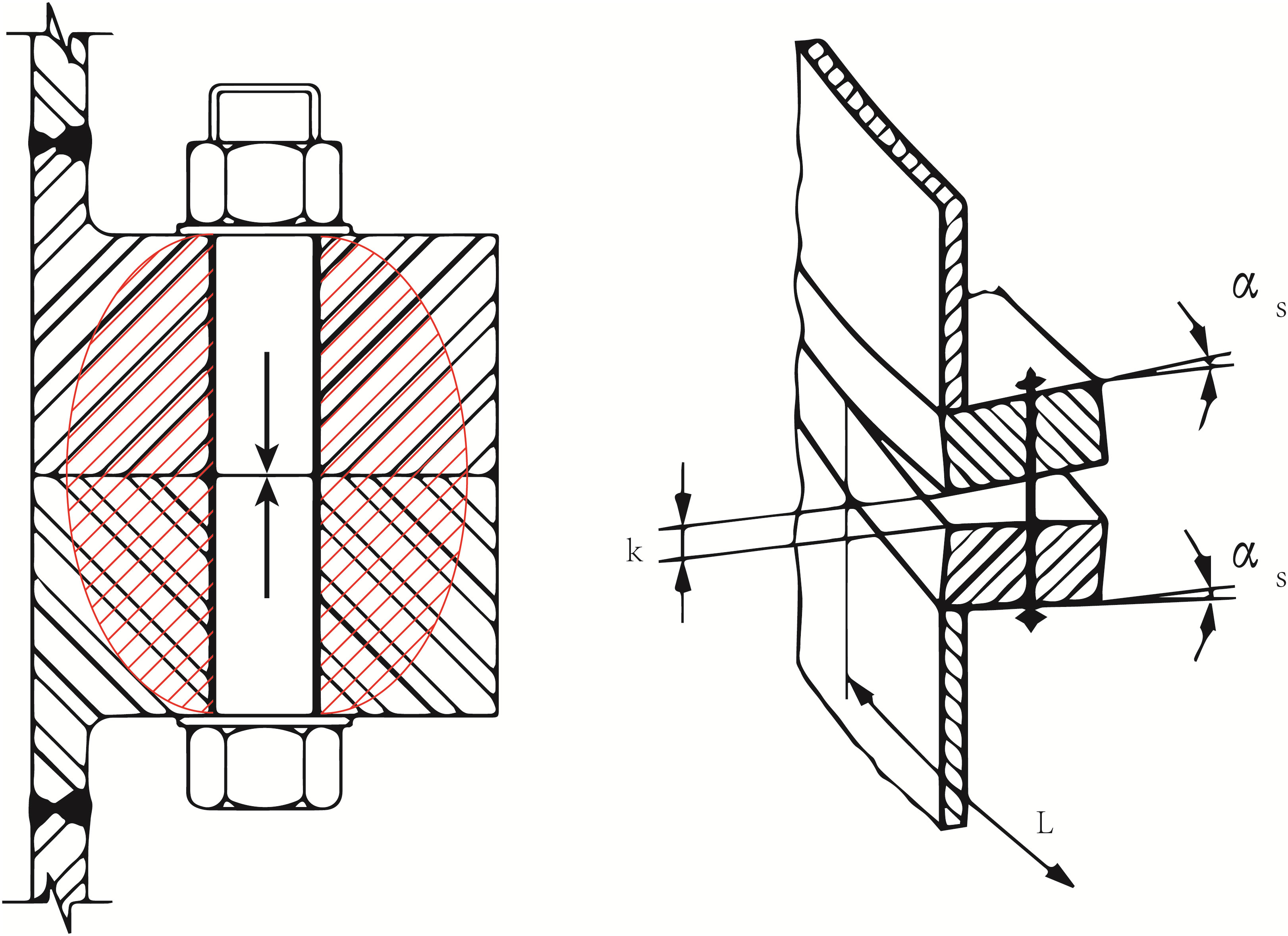
Figure 7 Clamp forces in a perfect bolted flange (left); the detailed configuration of flatness divergence (right).
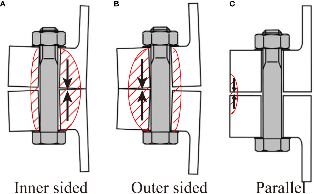
Figure 8 Clamp forces in imperfect bolted flanges. (A) Inner sided; (B) Outer sided; (C) Parallel.
DIN 18088-3 (DIN (2019)) as well as the DNVGL-ST-0126 (DNVGL (2018)) have stated the requirement for imperfect flanges. The flatness divergence of one flange must be less than 2 mm in length over the entire flange circumference and less than 1 mm over a 30° segment. However, Weijtjens et al. (2021) pointed out that this requirement is semi-empirical and it does not consider those geometric imperfection explicitly. With the widely use of large flange and bolt diameters, it becomes more and more challenging to fulfil all these requirements during the OWT installations.
The flatness divergence may significantly influence the stress distribution over the whole flanges when external loading is acting on the tower. According to the standard (DASt (2013)), load transfer functions are recommended to describe the relationship between external force Z and bolt load Fb. With the increase of external forces, this process can be described in four stages:
1. Stresses between the flanges are dominant by bolt preload, and the contact is closed.
2. Stresses increase and some small imperfection-induced openings show up. In this case, the clamp solid begins to degrade.
3. Stresses keeps on increasing and the openings become large.
4. Flanges and bolts begin to deform plastically.
For fatigue assessment, the first stage account most for fatigue life. The other stages are relatively less important. When clamp solids emerge, the stress may distribute differently depending on the geometric perfection or imperfection. Figure 9 illustrates that imperfect flange with flatness divergence has higher bolt load and variance which is more vulnerable to fatigue damage.
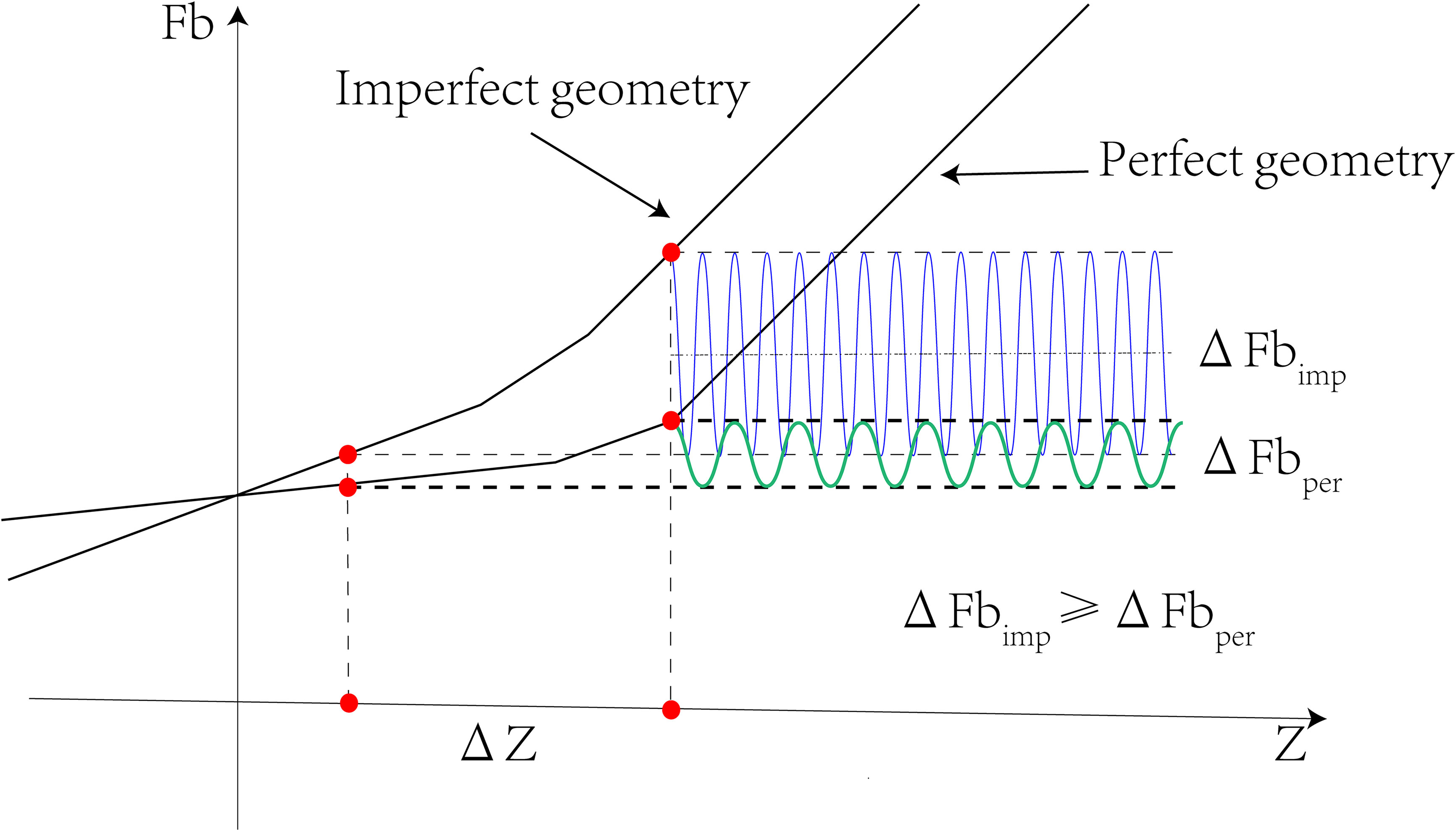
Figure 9 The relationship between external force Z and bolt load Fb under perfect and imperfect geometry.
Schaumann and Seidel (2002) measured the stresses in the ring flanges of an onshore wind turbine. The result indicates that there is a strong fluctuation of load transfer functions due to the influence of geometric imperfections. Another research (Weijtjens et al., 2021) found the existence of flatness divergences, but all of them satisfy the requirement of standards. FE models were built and their result was compared with the measurement. The comparison revealed that it is necessary to consider the effect of flatness divergence to match the FE analysis result with on-site measurements.
6.2 Bolt loosening
Ring-shaped flanges are widely used to connect the tubular steel segments of offshore wind turbine towers. With the high demand of large capacity generators, the bolts’ size has grown to M36 or even bigger (Braithwaite and Mehmanparast, 2019). For safety purpose, high preload forces are applied on flanges by tightening bolts to keep flange connections close and strong. However, considerable observations have been recorded that the flange connections may turn loose during installations and operations (Badrkhani Ajaei and Soyoz, 2020). The bolt loosening reduces the clamp forces between flange parts and lowers the strength of connections (Wegener et al., 2020).
According to standards and guidelines (DNVGL (2016b); IEC, 2005; GL, 2010), all bolts in a flange should be preloaded uniformly. However, in the installation stage, this requirement is hardly fully satisfied due to the elastic interaction between nearby bolts or flanges. Tightening a bolt may affect the other tightened bolts and reduce their preloading forces. One practical solution is to tighten all these bolts in a scientific sequence with a limited number of passes to minimize the variation of their preloading forces (Tsuji and Nakano, 2002; Abid and Nash, 2006; Nassar et al., 2010; Braithwaite and Mehmanparast, 2019). Another reason of un-uniform preloading is that the accurate on-site measurement of preloading forces is still a challenge to engineers. Meisterling (2010) monitored the preload forces of a series of M36 bolts, and found that the standard deviation of these bolts preload forces is more than 12%. Nagata et al. (2006) measured the bolt preloading forces in a vessel and indicated that the scatter of the preloads in the bolts of a flange can reach 45.2% of the intended preload. In addition, self-loosening of bolts is often found during OWTs’ operations. It has been widely accepted that preloaded bolts may loosen themself when subjected to long term vibrations or cyclic loadings. Cyclic loadings are the source of fatigue damage. When they loosen the preloaded bolts and influence the cyclic stress fluctuations, OWT towers are more vulnerable to fatigue failures.
To investigate the effect of bolt preload level on fatigue strength of ring shaped flange connections, Ajaei and Soyoz (Badrkhani Ajaei and Soyoz, 2020) performed the fatigue assessment on a finite element model of the maximal-loaded segment of the bolted connection in an on-shore wind turbines. The flanges are connected by 88 M36 bolts with a designed preload level of 510kN. In order to simulate the process of bolt loosening, five preload levels are applied as 510kN, 255kN, 127.5kN, 51kN and 10-6 kN. In the numerical model, the upper edge is applied with external loadings (axial forces and bending moments), and the lower edge is fixed. The time series of bolt stress is shown in Figure 10. The fatigue damage with different preload levels was calculated based on S-N curves. This research revealed that the reduction of bolt preload level from 510kN to nearly 0kN can cause an increase of the cyclic bolt stress ranges and result in more fatigue damage. In addition, the bending stresses in higher preload levels contribute much more to fatigue damage than in lower preload levels.
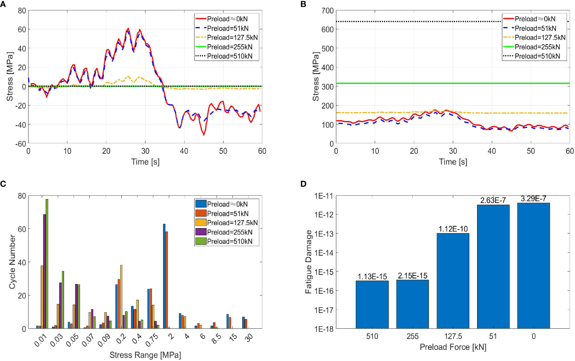
Figure 10 (A) Time series of bolt stress with averages removed under different preloads; (B) Time series of bolt stress under different preloads; (C) stress range histograms; (D) fatigue damage under different preloads for one minute loading (Badrkhani Ajaei and Soyoz, 2020).
6.3 Tower inclination
Initial imperfections in flanges or improper installations of wind turbines may lead to tower inclination of fixed OWTs. DNVGL-ST-N001 (DNVGL (2016c)) requires that the relative motion of tilt is 2° in the lifting operation of upper modules. DNVGL-ST-0126 (DNVGL (2018)) states that the total tolerance for the tower axis tilt is 0.25°. However, the research on the tower inclination induced by initial imperfections of flange is rather limited, because its impact is much less significant than inclinations from other sources. For fixed offshore wind turbines, the surrounding seabed soil is losing strength and stiffness under cyclic external loadings and scour, and the tower inclination is mainly due to the soil-pile interface behaviors (Zhou et al., 2021).
Tower inclinations for FWTs are, however, inevitable due to their floating foundations. FWTs typically experience motions from six DOFs as surge, sway, heave, roll, pitch and yaw (Jonkman, 2007; Jonkman, 2009). Considerable research has been conducted for the impact of motions on the aerodynamic and hydrodynamic performance of a FWT, including surge (Hu et al., 2015; Micallef and Sant, 2015; Tran and Kim, 2016), heave (Khosravi, 2015), pitch (Jeon et al., 2014; Hu et al., 2016; Wen et al., 2018; Wen et al., 2018; Ortolani et al., 2020), yaw (Miao et al., 2016) and the combined motion like pitch & yaw (Tran and Kim, 2015), pitch & surge (Bayati et al., 2016) or even surge, heave & pitch (Liu et al., 2016). Some research concluded that up to 10° inclination is acceptable for FWTs (Sebastian and Lackner, 2012a; Rockel et al., 2014; Antonutti et al., 2016).
Among all the motions, pitch and surge are believed to have the most significant impact on FWT’s aerodynamic performance by different ways, as listed in Table 3. Fang et al. (Fang et al., 2020; Fang et al., 2021) validated their numerical model of a 1:50 scale FOWT by experiments, and investigated the change of rotor’s aerodynamics including thrust, torque and rotor power, which may lead to cyclic loadings on the flange connections and result in fatigue damage. Their comparisons indicates that pitch and surge motions with higher amplitude can result in higher range of thrust and torque variations, as shown in Figure 11. Antonutti et al. (2016) conducted study focusing on the effect of large inclination on the hydrodynamic performance of a FOWT and concluded that large inclinations can amplify the motions of FOWTs. The authors further pointed out that such impact is also very sensitive to the relative directions of wind and waves.
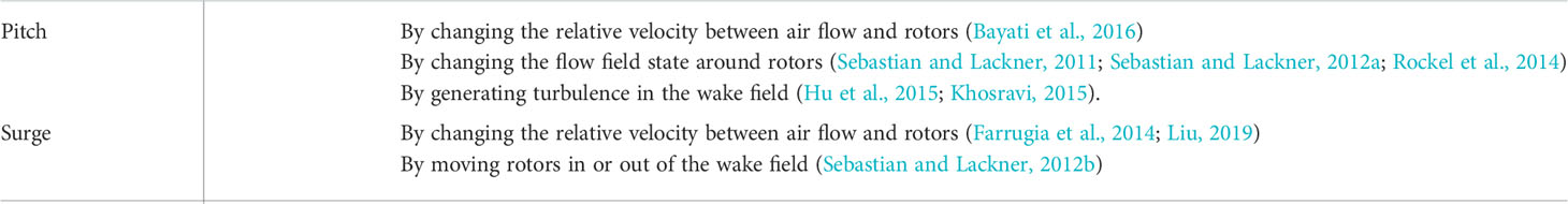
Table 3 The impact of pitch and surge on aerodynamics of FWTs.
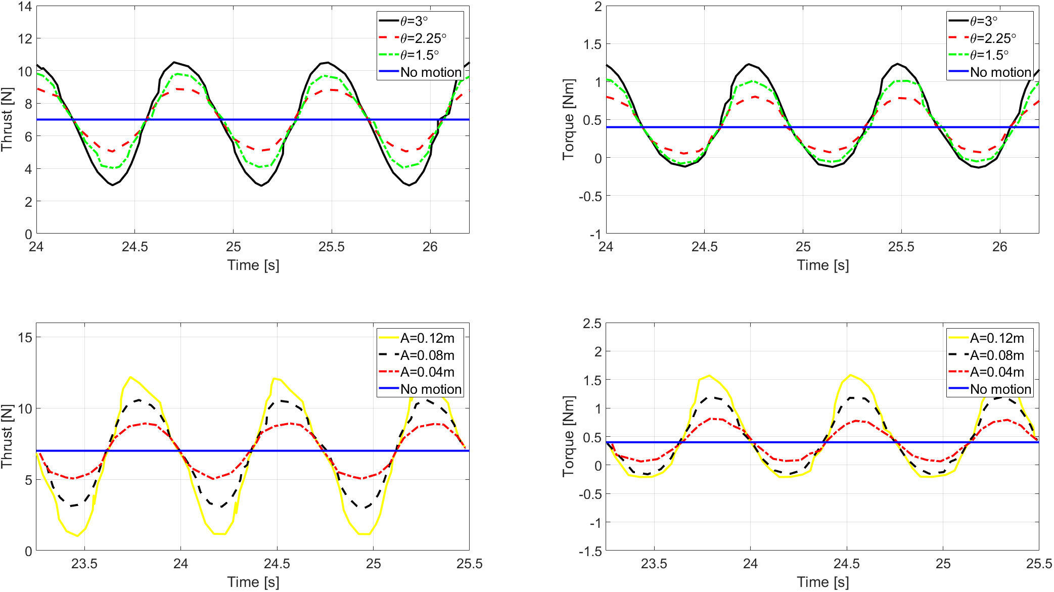
Figure 11 Comparison of the thrust and torque among different pitch motion (up) and surge motion (down) (Fang et al., 2020; Fang et al., 2021).
7 Conclusions
This paper provides a comprehensive review of the initial imperfections’ impact on the fatigue assessment of FWT towers’ flange connections. Among the massive recent installations of OWTs in China, three types of initial imperfections were reported most likely to occur. They are flatness divergence, bolt loosening and tower inclination. As the global wind power industry tends to develop progressively towards deepwater offshore with FWTs, the impact of initial imperfections can be even more critical thus further studies in the topic are is warranted and timely.
The initial imperfections are likely to occur during manufacture and installations of FWTs, which has a negative impact on the fatigue strength of bolted flange connections. This paper reviewed recent literature about the impact of these initial imperfections. The main conclusions are as follows:
1. Flatness divergence opens the upper and lower flange parts and results in imperfect geometric conditions. The clamp force may distribute eccentrically from the bolt’s longitudinal axis when preloading, and the stress fluctuations in the hotspots is highly dependent on the imperfect geometric conditions. The flatness divergence makes the flange connections more vulnerable to fatigue damage than under perfect conditions.
2. Large size bolts in the flange connections may lose preloading forces due to the vibration during the installation or operation stages. The self-loosening of preload forces may lead to an increase of cyclic stress range and result in a reduction of fatigue life.
3. Standards and guidelines have strict requirements for the tower tilt angle of fixed OWTs. However, due to the floating substructures, it is impossible to require FWTs to limit their tower tilt as much as fixed wind turbines. The research on FWTs’ inclination reveals that the pitch and surge motions may enlarge the variation of torque and thrust, which also has a negative impact on the fatigue strength of flange connections.
Author contributions
TZ: Conceptualization, Methodology, Software, Investigation, Formal Analysis, Writing - Original Draft XN: Picture Making XJ: Picture Making ML: Validation, Corresponding author LT: Writing - Review & Editing. All authors contributed to the article and approved the submitted version.
Funding
This research is supported by the Shandong Provincial Key Laboratory of Ocean Engineering with grant No. kloe202010, the Natural Science Foundation of Jiangsu Province (Grant No. BK20220654, BK20190962) and the National Natural Science Foundation of China (Grant No. 52001144). The authors would like to thank the Key R & D Projects in Guangdong Province (No. 2020B1111500001) for their financial supports.
Conflict of interest
The authors declare that the research was conducted in the absence of any commercial or financial relationships that could be construed as a potential conflict of interest.
Publisher’s note
All claims expressed in this article are solely those of the authors and do not necessarily represent those of their affiliated organizations, or those of the publisher, the editors and the reviewers. Any product that may be evaluated in this article, or claim that may be made by its manufacturer, is not guaranteed or endorsed by the publisher.
References
Abid M., Nash D. H. (Eds.) (2006). Joint relaxation behavior of gasketed bolted flanged pipe joint during assembly. 2nd WSEAS international conference on applied and theoretical mechanics (Venice, Italy).
Alonso-Martinez M., Adam J. M., Alvarez-Rabanal F. P., del Coz Díaz J. J. (2019). Wind turbine tower collapse due to flange failure: FEM and DOE analyses. Eng. Failure Analysis. 104, 932–949. doi: 10.1016/j.engfailanal.2019.06.045
Antonutti R., Peyrard C., Johanning L., Incecik A., Ingram D. (2016). The effects of wind-induced inclination on the dynamics of semi-submersible floating wind turbines in the time domain. Renewable Energy. 88, 83–94.
DIN (2019). Design standard - Structures for wind turbines and platforms – part 3: Steel structures. DIN-18088-3.
DASt. (2013). Hot-dip galvanized HV-bolt assemblies of the M36 to M72 in accordance with EN 14399–4, EN 14399–6. Guideline 0212013.
Badrkhani Ajaei B., Soyoz S. (2020). Effects of preload deficiency on fatigue demands of wind turbine tower bolts. J. Constructional Steel Res. 166, 105933. doi: 10.1016/j.jcsr.2020.105933
Bayati I., Belloli M., Bernini L., Zasso A. (2016). Wind tunnel validation of AeroDyn within LIFES50+ project: imposed surge and pitch tests. J. Physics: Conf. Series. 753, 092001. doi: 10.1088/1742-6596/753/9/092001
Benedetti M., Fontanari V., Battisti L. (2013). Structural health monitoring of wind towers: residual fatigue life estimation. Smart Materials Structures. 22 (4), 045017. doi: 10.1088/0964-1726/22/4/045017
Blachowski B., Gutkowski W. (2016). Effect of damaged circular flange-bolted connections on behaviour of tall towers, modelled by multilevel substructuring. Eng. Structures. 111, 93–103. doi: 10.1016/j.engstruct.2015.12.018
Braithwaite J., Mehmanparast A. (2019). Analysis of tightening sequence effects on preload behaviour of offshore wind turbine M72 bolted connections. Energies 12 (23), 4406. doi: 10.3390/en12234406
Couchaux M., Hjiaj M., Ryan I., Bureau A. (2017). Effect of contact on the elastic behaviour of tensile bolted connections. J. Constructional Steel Res. 133, 459–474. doi: 10.1016/j.jcsr.2016.10.012
Ding J., Chen X. (2013). Assessing small failure probability by importance splitting method and its application to wind turbine extreme response prediction. Eng. Structures. 54, 180–191. doi: 10.1016/j.engstruct.2013.03.051
Do T. Q., Mahmoud H., van de Lindt J. W. (2015). Fatigue life of wind turbine tower bases throughout Colorado. J. Perform. Constructed Facilities. 29 (4), 04014109. doi: 10.1061/(ASCE)CF.1943-5509.0000612
Dong W., Moan T., Gao Z. (2012). Fatigue reliability analysis of the jacket support structure for offshore wind turbine considering the effect of corrosion and inspection. Reliabil Eng. System Safety. 106, 11–27. doi: 10.1016/j.ress.2012.06.011
Do T. Q., van de Lindt J. W., Mahmoud H. (2015). Fatigue life fragilities and performance-based design of wind turbine tower base connections. J. Struct. Engineering. 141 (7), 04014183. doi: 10.1061/(ASCE)ST.1943-541X.0001150
Fang Y., Duan L., Han Z., Zhao Y., Yang H. (2020). Numerical analysis of aerodynamic performance of a floating offshore wind turbine under pitch motion. Energy. 192, 116621. doi: 10.1016/j.energy.2019.116621
Fang Y., Li G., Duan L., Han Z., Zhao Y. (2021). Effect of surge motion on rotor aerodynamics and wake characteristics of a floating horizontal-axis wind turbine. Energy. 218, 119519. doi: 10.1016/j.energy.2020.119519
Farrugia R., Sant T., Micallef D. (2014). Investigating the aerodynamic performance of a model offshore floating wind turbine. Renewable Energy. 70, 24–30. doi: 10.1016/j.renene.2013.12.043
Gao J., Ma X., Dong G., Chen H., Liu Q., Zang J. (2021). Investigation on the effects of Bragg reflection on harbor oscillations. Coast. Engineering. 170, 103977. doi: 10.1016/j.coastaleng.2021.103977
Gao J., Ma X., Zang J., Dong G., Ma X., Zhu Y., et al. (2020). Numerical investigation of harbor oscillations induced by focused transient wave groups. Coast. Engineering. 158, 103670. doi: 10.1016/j.coastaleng.2020.103670
Gao J., Sweetman B., Tang S. (2022). Multiaxial fatigue assessment of floating offshore wind turbine blades operating on compliant floating platforms. Ocean Engineering. 261, 111921. doi: 10.1016/j.oceaneng.2022.111921
Goupee A. J., Kimball R. W., Dagher H. J. (2017). Experimental observations of active blade pitch and generator control influence on floating wind turbine response. Renewable Energy. 104, 9–19. doi: 10.1016/j.renene.2016.11.062
Heistermann C., Husson W., Veljkovic M. (Eds.) (2009). Flange connection vs. friction connection in towers for wind turbines. Nordic steel construction conference (Malmö, Sweden: Stålbyggnadsinstitutet.).
He M., Li Z., Ma R., Huang D., Liu K., Pei Z. (2016). Experimental investigation and on–site measurement of reverse–balanced flange connections in wind turbine towers. Adv. Struct. Engineering. 18 (8), 1215–1225. doi: 10.1260/1369-4332.18.8.1215
Hobbs J. (2000). The effect of eccentric loading on the fatigue performance of high-tensile bolts. Int. J. Fatigue. 22 (6), 531–538. doi: 10.1016/S0142-1123(00)00004-9
Horas C. S., De Jesus A. M. P., Ribeiro D., Calçada R. (2022). Efficient multiscale methodology for local stress analysis of metallic railway bridges based on modal superposition principles. Eng. Failure Analysis. 138, 106391. doi: 10.1016/j.engfailanal.2022.106391
Hu H., Khosravi M., Sarkar P. (Eds.) (2016). An experimental investigation on the aeromechanic performance and wake characteristics of a wind turbine model subjected to pitch motions. 34th wind energy symposium (San Diego, California, USA: American Institute of Aeronautics and Astronautics, Inc.).
Hu H., Morteza Khosravi M., Sarkar P. (2015). An experimental investigation on the performance and the wake characteristics of a wind turbine subjected to surge motion Proceedings of the 33rd Wind Energy Symposium. (Kissimmee, Florida). doi: 10.2514/6.2015-1207
Hu Y., Yang J., Baniotopoulos C., Wang X., Deng X. (2020). Dynamic analysis of offshore steel wind turbine towers subjected to wind, wave and current loading during construction. Ocean Engineering. 216, 108084. doi: 10.1016/j.oceaneng.2020.108084
Jakubowski A., Schmidt H. (2003). Experimentelle untersuchungen an vorgespannten ringflanschstößen mit imperfektionen, [Experimental analysis on preloaded ring flange connections with imperfections]. Stahlbau. 72 (3), 188–196. doi: 10.1002/stab.200300660
Jeon M., Lee S., Lee S. (2014). Unsteady aerodynamics of offshore floating wind turbines in platform pitching motion using vortex lattice method. Renewable Energy. 65, 207–212. doi: 10.1016/j.renene.2013.09.009
Jonkman J. M. (2007). Dynamics modeling and loads analysis of an offshore floating wind turbine. doi: 10.2172/921803
Jonkman J. M. (2009). Dynamics of offshore floating wind turbines-model development and verification. Wind Energy. 12 (5), 459–492. doi: 10.1002/we.347
Khosravi M. (2015). An experimental study on the near wake characteristics of a wind turbine model subjected to surge, pitch, and heave motions (United States: Iowa State University). doi: 10.31274/etd-180810-3919
Kvittem M. I., Moan T. (2015). Time domain analysis procedures for fatigue assessment of a semi-submersible wind turbine. Mar. Structures. 40, 38–59. doi: 10.1016/j.marstruc.2014.10.009
Liu Y. (2019). An optimization-driven dynamic vehicle routing algorithm for on-demand meal delivery using drones. Comput. Operations Res. 111, 1–20. doi: 10.1016/j.cor.2019.05.024
Liu Y., Xiao Q., Incecik A., Wan D. C. (2016). Investigation of the effects of platform motion on the aerodynamics of a floating offshore wind turbine. J. Hydrodynamics. 28 (1), 95–101. doi: 10.1016/S1001-6058(16)60611-X
Luan C., Gao Z., Moan T. (2017). Development and verification of a time-domain approach for determining forces and moments in structural components of floaters with an application to floating wind turbines. Mar. Structures. 51, 87–109. doi: 10.1016/j.marstruc.2016.10.002
Luan C., Gao Z., Moan T. (2018). Comparative analysis of numerically simulated and experimentally measured motions and sectional forces and moments in a floating wind turbine hull structure subjected to combined wind and wave loads. Eng. Structures. 177, 210–233. doi: 10.1016/j.engstruct.2018.08.021
Lüddecke F., Victor A., Schwedler M. (2019). Analyse des einflusses fertigungsbedingter imperfektionen auf die schraubenkraft an großen ringflanschverbindungen, [Analysis of the influence of flange imperfections due to fabrication tolerances on the bolt force in large ring flange connections]. Der Prüfinegieur 5, 42–57.
Márquez F. P. G., Pérez J. M. P., Marugán A. P., Papaelias M. (2016). Identification of critical components of wind turbines using FTA over the time. Renewable Energy. 87, 869–883. doi: 10.1016/j.renene.2015.09.038
Mehmanparast A., Lotfian S., Vipin S. P. (2020). A review of challenges and opportunities associated with bolted flange connections in the offshore wind industry. Metals. 10 (6), 732. doi: 10.3390/met10060732
Meisterling J. R. (2010). Joint integrity monitoring using permanent ultrasonic bolt load transducers Proceedings of the ASME 2010 Power Conference. (Chicago, Illinois, USA) 319–324. doi: 10.1115/POWER2010-27046
Miao W., Li C., Yang J., Xie X. (2016). Numerical investigation of the yawed wake and its effects on the downstream wind turbine. J. Renewable Sustain. Energy. 8 (3), 033303. doi: 10.1063/1.4953791
Micallef D., Sant T. (2015). Loading effects on floating offshore horizontal axis wind turbines in surge motion. Renewable Energy. 83, 737–748. doi: 10.1016/j.renene.2015.05.016
Mostafa N., Murai M., Nishimura R., Fujita O., and Nihei Y (2012). Study of motion of spar-type floating wind turbines in waves with effect of gyro moment at inclination. J. Naval Architect Mar. Engineering. 9 (1), 67–79. doi: 10.3329/jname.v9i1.10732
Nagata S., Sawa T., Hamamoto S. (Eds.) (2006). Effects of scatter in bolt preload on the sealing performance in bolted flange connections with cover of pressure vessel under internal pressure. ASME pressure vessels and piping division conference (Vancouver, British Columbia, Canada).
Nassar S. A., Wu Z., Yang X. (2010). Achieving uniform clamp load in gasketed bolted joints using a nonlinear finite element model. J. Pressure Vessel Technol. 132 (3), 031205. doi: 10.1115/1.4001040
Oechsner M., Simonsen F., Schaumann P., Eichstdt R. (2015). “Experimental and analytical assessment of the fatigue strength of bolts with Large dimensions under consideration of boundary layer effects,” in METEC and 2nd ESTAD, (Düsseldorf, Germany).
Ortolani A., Persico G., Drofelnik J., Jackson A., Sergio Campobasso M. (2020). Computational fluid dynamics analysis of floating offshore wind turbines in severe pitching conditions. J. Eng. Gas Turbines Power 142 (12), 12100. doi: 10.1115/1.4048776
Pollino M. C., Huckelbridge A. A. (Eds.) (2012). In-situ measurements of fatigue demands on a wind turbine support structure. IEEE energytech (Cleveland, OH, USA).
Ragan P., Manuel L. (2016). Comparing estimates of wind turbine fatigue loads using time-domain and spectral methods. Wind Engineering. 31 (2), 83–99. doi: 10.1260/030952407781494494
Redondo R., Mehmanparast A. (2020). Numerical analysis of stress distribution in offshore wind turbine M72 bolted connections. Metals. 10 (5), 689. doi: 10.3390/met10050689
Rockel S., Camp E., Schmidt J., Peinke J., Cal R., Hölling M. (2014). Experimental study on influence of pitch motion on the wake of a floating wind turbine model. Energies. 7 (4), 1954–1985. doi: 10.3390/en7041954
Schaumann P., Eichstädt R. (2015). “Fatigue assessment of high-strength bolts with very Large diameters in substructures for offshore wind turbines,” in he Twenty-fifth International Ocean and Polar Engineering Conference, Hawaii, USA.
Schaumann P., Seidel M. (2022) Ermüdungsbeanspruchung geschraubter ringflanschverbindungen bei windenergieanlagen, [Fatigue loading of bolted ring flange connections for wind turbines]. Stahlbau 71(3):204–11. doi: 10.1002/stab.200200570
Schwingshackl C. W., Petrov E. P. (2012). Modelling of flange joints for the nonlinear dynamic analysis of gas turbine engine casings Proceedings of the ASME Turbo Expo 2012: Turbine Technical Conference and Exposition (Copenhagen, Denmark) 7, 1283–1293. doi: 10.1115/GT2012-69281
Sebastian T., Lackner M. (Eds.) (2011). Offshore floating wind turbines an aerodynamic perspective. Proceedings of the 49th AIAA aerospace sciences meeting (Orlando, Florida, USA).
Sebastian T., Lackner M. (2012a). Analysis of the induction and wake evolution of an offshore floating wind turbine. Energies. 5 (4), 968–1000. doi: 10.3390/en5040968
Sebastian T., Lackner M. (Eds.) (2012b). Unsteady near-wake of offshore floating wind turbines. 50th AIAA aerospace sciences meeting including the new horizons forum and aerospace exposition (Tennessee, USA).
Seidel M. (Ed.) (2001). Measuring fatigue loads of bolts in ring flange connections. European wind energy conference (Copenhagen, Denmark).
Seidel M. (2018). Tolerance requirements for flange connections in wind turbine support structures. Stahlbau. 87 (9), 880–887. doi: 10.1002/stab.201810050
Shirani M., Härkegård G. (2011a). Fatigue life distribution and size effect in ductile cast iron for wind turbine components. Eng. Failure Analysis. 18 (1), 12–24. doi: 10.1016/j.engfailanal.2010.07.001
Shirani M., Härkegård G. (2011b). Large Scale axial fatigue testing of ductile cast iron for heavy section wind turbine components. Eng. Failure Analysis. 18 (6), 1496–1510. doi: 10.1016/j.engfailanal.2011.05.005
Sutherland H. J. (1999). On the fatigue analysis of wind turbines (Albuquerque, New Mexico, and Livermore, California, United States: Sandia National Laboratories).
Tran T. T., Kim D. H. (2015). The aerodynamic interference effects of a floating offshore wind turbine experiencing platform pitching and yawing motions. J. Mechanical Sci. Technol. 29 (2), 549–561. doi: 10.1007/s12206-015-0115-0
Tran T. T., Kim D.-H. (2016). A CFD study into the influence of unsteady aerodynamic interference on wind turbine surge motion. Renewable Energy. 90, 204–228. doi: 10.1016/j.renene.2015.12.013
Tsuji H., Nakano M. (2002). Bolt preload control for bolted flange joint Proceedings of the ASME 2002 Pressure Vessels and Piping Conference. Analysis of Bolted Joints. (Vancouver, BC, Canada) 163–170. doi: 10.1115/PVP2002-1094
Van-Long H., Jean-Pierre J., Jean-François D. (2013). Behaviour of bolted flange joints in tubular structures under monotonic, repeated and fatigue loadings I: Experimental tests. J. Constructional Steel Res. 85, 1–11. doi: 10.1016/j.jcsr.2013.02.011
Wang S., Moan T., Jiang Z. (2022). Influence of variability and uncertainty of wind and waves on fatigue damage of a floating wind turbine drivetrain. Renewable Energy. 181, 870–897. doi: 10.1016/j.renene.2021.09.090
Wang Y. Q., Zong L., Shi Y. J. (2013). Bending behavior and design model of bolted flange-plate connection. J. Constructional Steel Res. 84, 1–16. doi: 10.1016/j.jcsr.2013.01.012
Wegener F., Seidel M., Glienke R., Marten F., Schwarz M. (2020). Numerische simulation von vorspannkraftverlusten in ringflanschverbindungen. Stahlbau. 89 (12), 1003–1015. doi: 10.1002/stab.202000055
Weijtjens W., Stang A., Devriendt C., Schaumann P. (2021). Bolted ring flanges in offshore-wind support structures - in-situ validation of load-transfer behaviour. J. Constructional Steel Res. 176, 106361. doi: 10.1016/j.jcsr.2020.106361
Wen B., Dong X., Tian X., Peng Z., Zhang W., Wei K. (2018). The power performance of an offshore floating wind turbine in platform pitching motion. Energy. 154, 508–521. doi: 10.1016/j.energy.2018.04.140
Wen B., Zhang Q., Wei S., Tian X., Peng Z. (Eds.) (2018). Comparisons between the typical wind shear and the wind shear induced by platform pitch motion for an offshore floating wind turbine. 37th international conference on ocean, offshore and Arctic engineering (Madrid, Spain).
Xu K., Shao Y., Gao Z., Moan T. (2019). A study on fully nonlinear wave load effects on floating wind turbine. J. Fluids Structures. 88, 216–240. doi: 10.1016/j.jfluidstructs.2019.05.008
Xu K., Zhang M., Shao Y., Gao Z., Moan T. (2019). Effect of wave nonlinearity on fatigue damage and extreme responses of a semi-submersible floating wind turbine. Appl. Ocean Res. 91, 101879. doi: 10.1016/j.apor.2019.101879
Zheng T., Chen N.-Z. (2022). Time-domain fatigue assessment for blade root bolts of floating offshore wind turbine (FOWT). Ocean Engineering. 262, 112201. doi: 10.1016/j.oceaneng.2022.112201
Zhou W., Guo Z., Wang L., Li J., Li Y., Rui S. (2021). Simplified t-z models for estimating the frequency and inclination of jacket supported offshore wind turbines. Comput. Geotechnics. 132, 103959. doi: 10.1016/j.compgeo.2020.103959
Zou T., Liu W., Li M., Tao L. (2021). Fatigue assessment on reverse–balanced flange connections in offshore floating wind turbine towers. 41st international conference on ocean, offshore & artic engineering. Proceedings of the 41st international conference on ocean, offshore & artic engineering, online doi: 10.1115/OMAE2021-64973
Keywords: floating wind turbine, fatigue assessment, flatness divergence, bolt loosening, tower inclination, initial imperfections
Citation: Zou T, Niu X, Ji X, Li M and Tao L (2022) The impact of initial imperfections on the fatigue assessment of tower flange connections in floating wind turbines: A review. Front. Mar. Sci. 9:1063120. doi: 10.3389/fmars.2022.1063120
Received: 06 October 2022; Accepted: 26 October 2022;
Published: 14 November 2022.
Edited by:
Wei-Bo Chen, National Science and Technology Center for Disaster Reduction, TaiwanCopyright © 2022 Zou, Niu, Ji, Li and Tao. This is an open-access article distributed under the terms of the Creative Commons Attribution License (CC BY). The use, distribution or reproduction in other forums is permitted, provided the original author(s) and the copyright owner(s) are credited and that the original publication in this journal is cited, in accordance with accepted academic practice. No use, distribution or reproduction is permitted which does not comply with these terms.
*Correspondence: Mingxin Li, enRfZHJlYW1AMTYzLmNvbQ==