 Yong-qiang Ling
 Lei Song1
95% of researchers rate our articles as excellent or good
Learn more about the work of our research integrity team to safeguard the quality of each article we publish.
Find out more
ORIGINAL RESEARCH article
Front. Ecol. Evol. , 18 September 2023
Sec. Environmental Informatics and Remote Sensing
Volume 11 - 2023 | https://doi.org/10.3389/fevo.2023.1249239
This article is part of the Research Topic Response and Catastrophe Mechanisms of Geotechnical Underground Exploration: Theories and Numerical Modeling View all 14 articles
The pile-anchor supporting structure is widely used in foundation pit engineering, it is particularly necessary for calculating lateral displacement of the pile-anchor supporting structure. The soil stress state is transformed by the additional stress caused by the prestress, thus the lateral displacement can be decreased own to pile-anchor supporting structure bearing active earth pressure had changed. Prestress as a concentrated force is decomposed into the horizontal component and vertical component, calculating the additional stress caused by the prestress and getting the formula of active earth pressure of considering the additional stress, setting up calculation model of the pile-anchor supporting structure. For typical examples of foundation pit engineering, the parameters are substituted into a program written based on derived formulas, and the elastic deformation superposition method is used to calculate the horizontal displacement of the pile anchor support structure. The comparison and verification is carried out by Finite element analysis. The influence of cohesion and friction angle on pile displacement, bending moment, and shear force has been studied. This study found that cohesion and friction angle have a significant impact on the displacement of pile anchor support structures.
Pile anchor support is an important support measure for deep foundation pits, which is combined with the anti-slip pile support method and the anchor rod support method. Its support principle combines the support principles of anti-slip piles and anchor cables, that is, the anti-slip force that prevents the slope from sliding in the foundation pit mainly comes from the anchoring force provided by the anchor rod and the anti-slip force provided by the anti-slip piles (Kung et al., 2007; Gao et al., 2020; Han et al., 2021; Zheng et al., 2021; Sun and Li, 2022a).
To study the bearing characteristics of pile anchor support structures in foundation pit support, slope support and other engineering projects, scholars have conducted a lot of work through numerical simulation(Lin et al., 2022; Sun and Li, 2022b; Yin and Fu, 2023) and experimental research (Fu and Hong, 2011; Li et al., 2020). Liu and Xu (2011) used the ADINA to simulate the deep foundation excavation and pile-anchor supports process, and analysis the support results of pile-anchor supports in ShenYang City. Through the field test of foundation pit engineering, Fu and Hong (2011) studied and analyzed the distribution and change law of reinforcement stress and pile moment during deep foundation pit excavation. Zhu and Wang (2013) combined field test and numerical analysis, taking pile-anchor support structure as an example, and proposed an analysis scheme combining monitoring of pile internal force and deformation with numerical analysis. Peng et al. (2014) analyzed the relationship between the pile-anchor support system and the nearby subway structure, and studied how to control the deformation of the nearby subway structure through the design of the pile-anchor support system. Saleem (2015) evaluated the main influencing factors of pile and anchor system collapse in five-star hotels under construction. In order to maintain the pile and backfill, earth anchors were installed during the excavation of the foundation pit. It is found that with the increase of grouting and ungrouting, 4 bolts are used for each bolt in the first row, and 5 bolts are used for the other three rows. On the basis of deformation coordination theory, Yin et al. (2016) deduced the solving model of working stress and prestress of PARBSS anchor rod. The results show that the calculation model is correct and the improved support system can be applied widely. Kung et al. (2007) used the finite element program analysis to analyze the main factors affecting the deformation of the retaining wall, and proposed a semi empirical calculation formula for the maximum deformation. According to the principle of survival of the fittest based on genetic algorithm, Wang (2021) designed the optimal design system of pile and anchor support structure for deep foundation pit. Combined with practical engineering examples, the research provides an important reference for the application of genetic algorithm in the field of foundation pit engineering. Recently, Liu et al. (2021) adopted monitoring techniques such as anchor rod axial force and deep horizontal displacement monitoring to study the mechanism of pile soil interaction in deep foundation pits. Taking a deep foundation pit in Xi’an as an example, Zheng et al. (2021) analyzed the redistribution of soil pressure and the variation of stress in the anchor pile support structure under local pile cutting conditions. To achieve a balance between structural capacity and cost-effectiveness, Chen et al. (2021) conducted research on different designs under pile anchor support. However, the above research lacks a calculation method for horizontal displacement of support piles considering prestress.
In this work, it is necessary to propose a simplified engineering algorithm that can quickly and accurately calculate the horizontal displacement of pile anchor support structure along the depth, taking into account the influence of anchor pre-stress in pile anchor support structure. This article calculates the horizontal displacement of the pile anchor support structure in the form of additional stress using the prestressed anchor rod, and uses the elastic deformation superposition method to calculate the horizontal displacement of the support structure. It is compared and verified with the current general design software and finite element analysis software for foundation pit support.
The calculation diagram of the pile anchor support structure is shown in Figure 1. The axis coordinates corresponding to anchor rod 1 are y1, y2····,yn and the prestressing force applied to anchor rod 1-n is T1, T2, ·····,Tn EI represents the bending stiffness of the support pile and the edge load of the foundation pit is Qi; Applying prestressing force Tn on the anchor rod causes additional stress to be generated in the soil on the side of the support pile along the anchor rod position. The prestressed anchor rod is divided into a free section and an anchoring section. The free section passes through the potential sliding surface, and the soil behind the potential sliding surface can be regarded as a stable zone. The soil in the sliding area on the front side of the potential sliding surface is subjected to prestressing Tn.
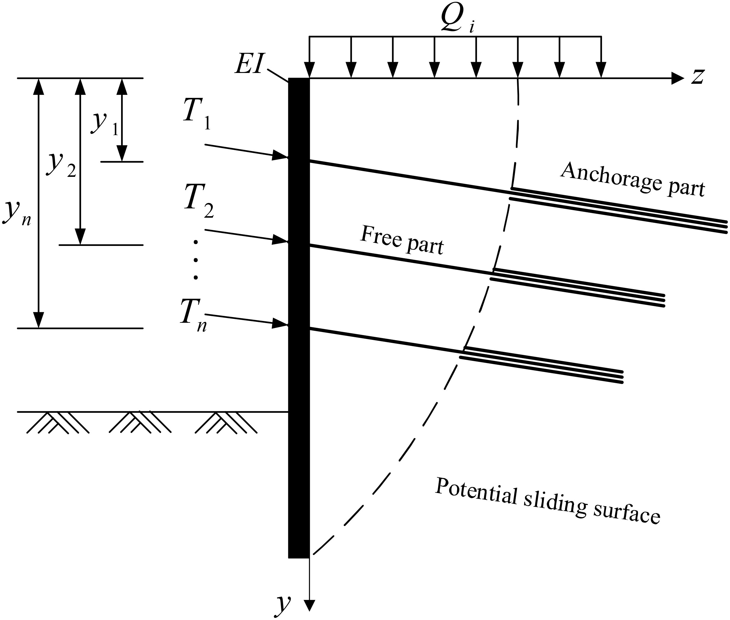
Figure 1 The Calculation diagram of pile-anchor supporting structure.
The prestressed Tn of the anchor rod in Figure 1 can be decomposed into two directions: vertical and horizontal, assuming the angle between Tn and the horizontal direction is α. The vertical component of the prestressed anchor rod is mainly transmitted to the soil at the bottom of the pile through the support pile. In practical engineering, the horizontal inclination angle α of the prestressed anchor rod is generally less than 15°, and the horizontal component is much greater than the vertical component. In terms of the deformation resistance of the support structure, the contribution of the horizontal component is much greater than the vertical component, so the role of the vertical component is temporarily ignored.
In this model, the anchor rod is actually arranged between two supporting piles, and after applying pre-stress to the anchor rod, additional stress is required at any point in the soil. This article draws inspiration from Sun Youlan’s (Poulos and Davis, 1974) “Elastic Solution of Rock and Soil Mechanics” to find the solution for additional stress at any point in the spatial semi infinite body under concentrated force. As shown in Figure 2, the additional stress at any point on the sliding surface of the horizontal component of pre-stress is:
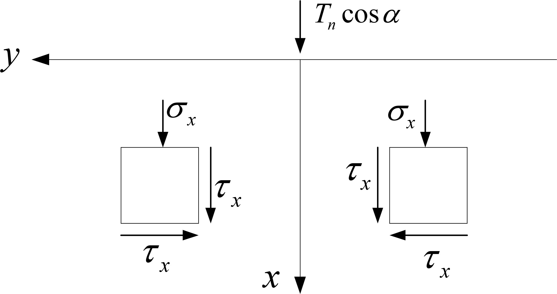
Figure 2 Normal force on the boundary of semi-infinite body.
where σx and τxy are normal and shear stresses respectively. In the calculation process, when the boundary of a semi infinite body is subjected to a normal concentrated force, and additional stress σv will also be generated, which plays a positive role in resisting deformation of the support structure. However, considering the influence of the top boundary condition of the supporting structure, σv has a large error between the calculated value and the actual value, so the influence of this stress is temporarily ignored in this paper.
After the prestressed anchor rod of the pile anchor support structure is applied, additional stress will be generated in the soil on the pile side. The calculation diagram is shown in Figure 3, and the soil pressure on both sides of the support pile will also change accordingly. The calculation of the active soil pressure on the pile side needs to consider the influence of the additional stress generated by the prestressed anchor rod. In Figure 2, the combined force of the additional stress in the x-axis direction is , and the combined force of the additional stress in the y-axis direction is zero. When calculating the active earth pressure on the side of the retaining pile, the non-limiting active earth pressure calculation method of clay proposed by Xu et al. (2020) is adopted, and the influence of additional stress in the soil is considered.

Figure 3 Calculation diagram of displacement.
where cm is the value of cohesive force development; φm is the limit value of internal friction angle; θ is the angle between the potential sliding surface of the wall bottom and the vertical direction; μ is the additional stress reduction coefficient, and the value of MM ranges from 0.2 to 0.5; c1 is the initial earth pressure; Sa is the failure ratio, ranging from 0.75 to 1.0; c1 is the weighted average value of cohesion; Sa is the displacement value required to reach the active state, and S(z) is the horizontal displacement value of the wall; γ1 is the weighted average of the soil mass density in the active zone; The axial coordinates of prestressed anchor rods T1, T2, and TN are y1, y2, and yn, respectively.
where α is the corner stress coefficient, which is related to the length, width, and depth h of the foundation pit; m is a constant, with an average value of 0.64.
The vertical direction is the y-axis, and the prestress at y=y1 is T1, at y=y2 is T2, and at ····· y=yn is Tn; Assuming a unit horizontal force is applied at y=y1, the bending moment at the corresponding position of the support pile is:
The shear force of the support pile under active soil pressure is:
The bending moment generated by the support pile is:
The horizontal displacement of the support pile under active soil pressure at y=y1 is:
Similarly, the horizontal displacement under passive earth pressure is:
Obtain the final horizontal displacement of y=y1 using the elastic superposition method:
Similarly, the horizontal displacement of the support pile at y=yn under active soil pressure
The horizontal displacement under passive earth pressure is:
The final horizontal displacement at y=yn is:
Similarly, the horizontal displacement of the pile anchor support structure at the bottom h of the foundation pit is calculated as:
By using the superposition method, the horizontal displacement curves of the support pile calculated by equations (17), (20), and (21) are superimposed to obtain the final horizontal displacement curve of the support pile considering anchor prestress. Compared to the current calculation rules of foundation pit design software, this article considers the influence of anchor pre-stress on the horizontal displacement of the support structure when calculating the horizontal displacement of the support pile. The additional stress generated by anchor pre-stress in the soil is used to calculate the horizontal displacement of the pile anchor support structure, which is more practical in engineering.
In this section, the finite element method was used to verify the correctness of the calculation method in this paper. A certain pile anchor support foundation pit project is used, and the excavation depth of the foundation pit is 19.8m. The design adopts pile anchor support structure, soil nail walls plus pile anchor support structure, and soil nail wall support structure support in areas with large local space. The foundation pit is classified as Level 1, with an overall stability coefficient of 1.3 and a partial load coefficient of 1.25. The parameters of the soil are shown in the Table 1.

Table 1 Soil parameters.
Figure 4 shows the mesh deformation diagram. Figure 5 shows a comparison between the finite element results and the calculation methods presented in this article. From the comparison in Figure 5, it can be observed that there are slight differences in the results obtained by the two calculation methods, but the overall trend is consistent. This indicates that the theoretical calculation method proposed in this article can be used to analyze the horizontal deformation of pile anchor support structures.
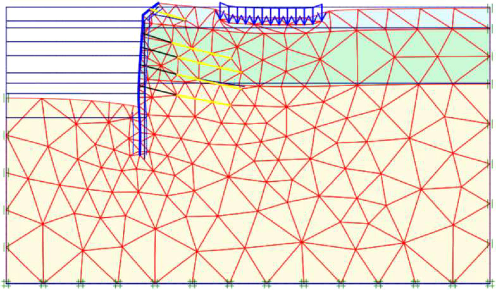
Figure 4 Mesh deformation diagram.
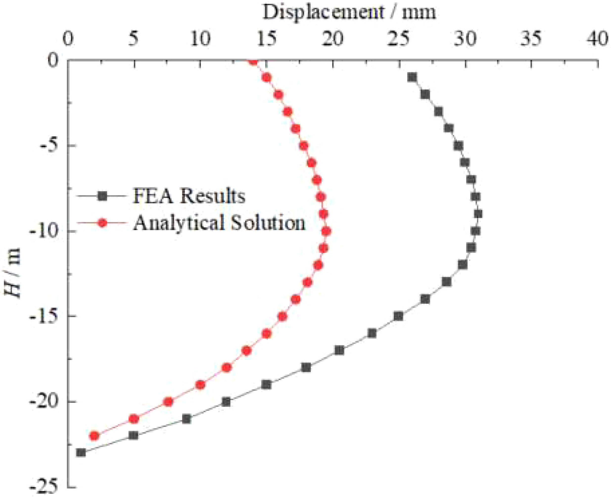
Figure 5 Comparison results between the calculation method in this article and the finite element method.
Figures 6–11 show the effects of soil cohesion and friction angle on the horizontal deformation, pile bending moment, and pile shear force of the support pile. The cohesive forces of the soil are selected as 10kPa, 20kPa, 30kPa, and 40kPa respectively; The internal friction angles are selected as 20°, 24°, 27°, and 30°.
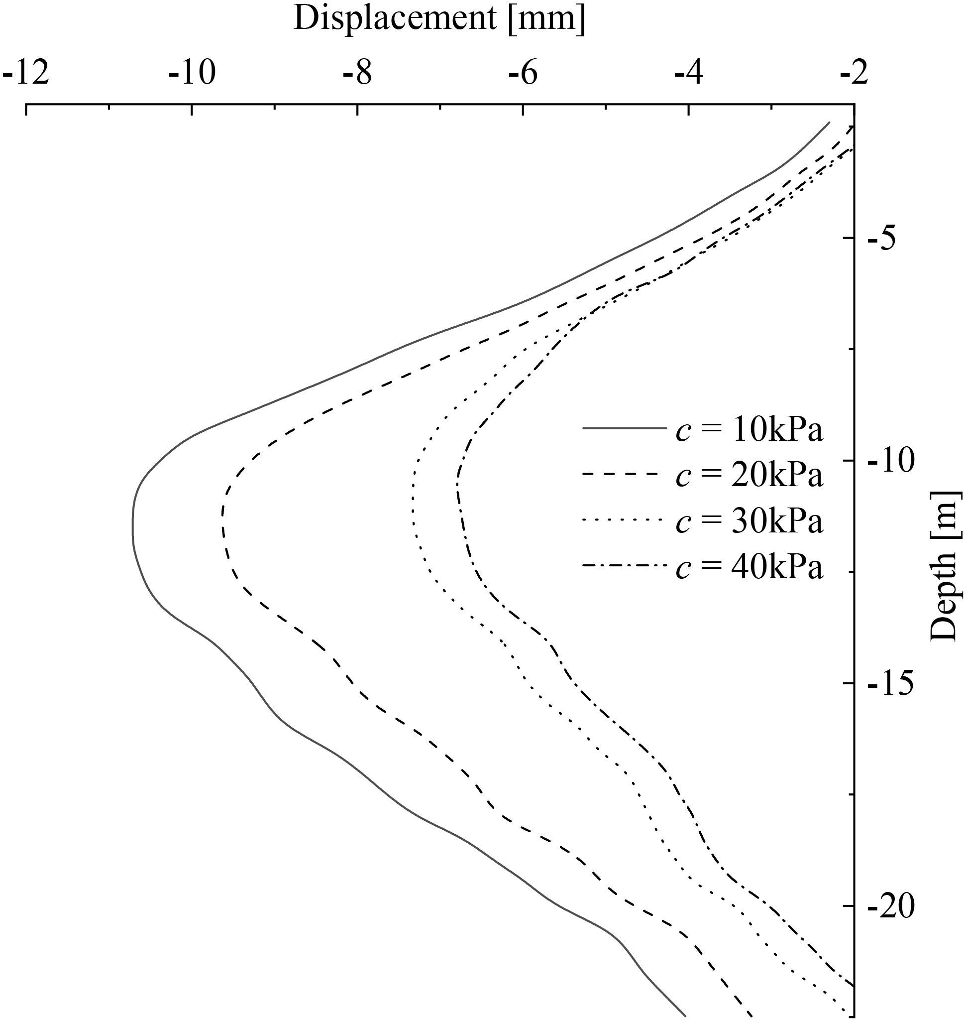
Figure 6 Effect of soil cohesion on pile displacement.
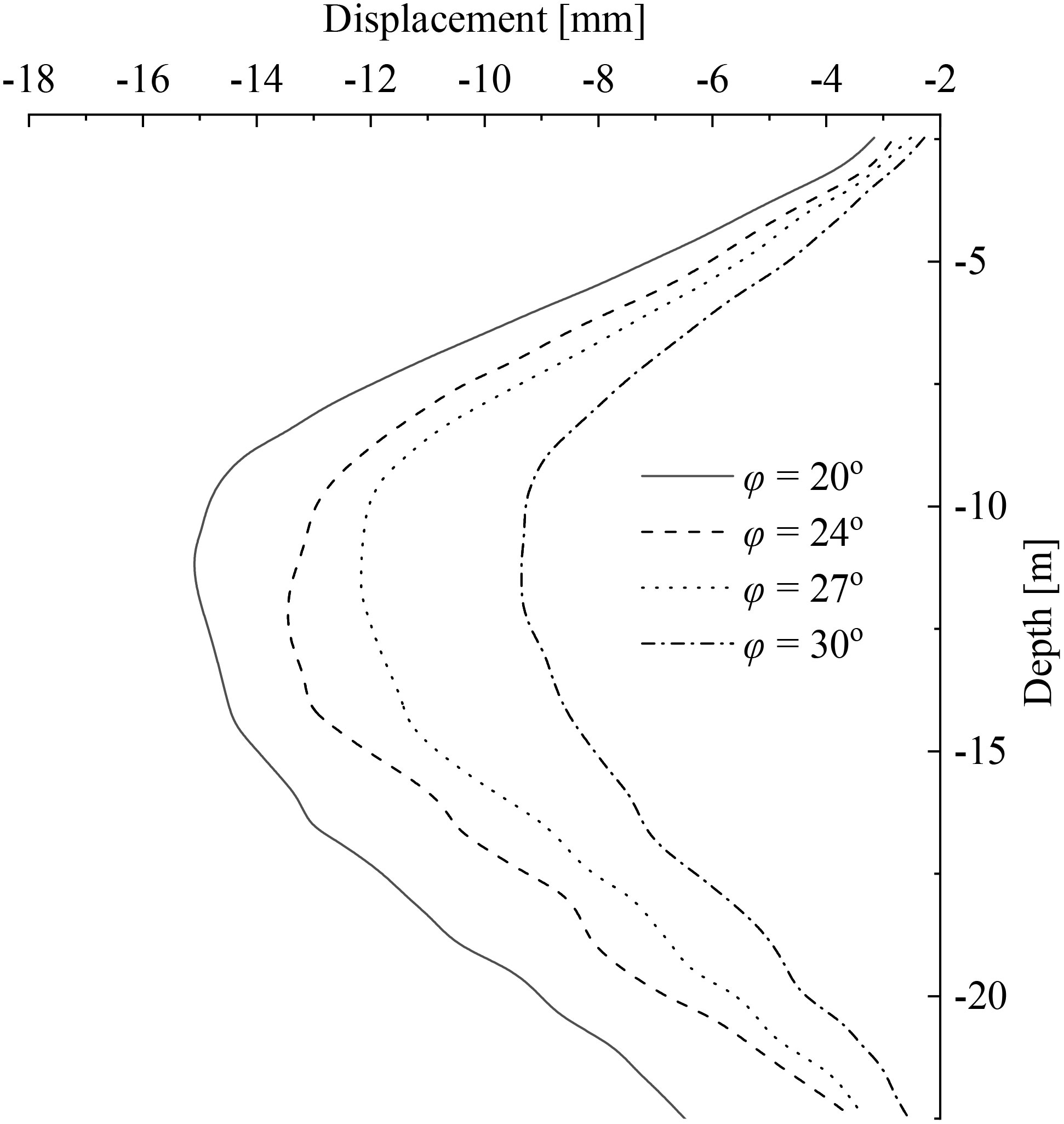
Figure 7 Effect of friction angle on pile displacement.
The influence of cohesion and friction angle on pile displacement is shown in Figures 6, 7. As shown in Figure 6, with the increase of soil cohesion c, the horizontal elastic resistance of the soil changes. The most direct impact on the support structure is that the horizontal displacement of the pile decreases accordingly. The horizontal displacement decreases most significantly at around -11.5m of the pile body, and the variation trend of the four curves shows a state of large in the middle and small at both ends, which better reflects the basic law of horizontal deformation of the support structure. At the same time, it is not difficult to see from the figure that at the top of the pile, the displacement of the pile body varies around -3.41mm under four different parameters. The overall trend of the entire curve is as follows: as the soil cohesion c value increases, the overall displacement of the pile body decreases. When the soil cohesion is taken as 10kPa, 20kPa, 30kPa, and 40kPa, the maximum horizontal displacement of the support pile is -10.74mm, -9.67mm, -7.36mm, and -6.82mm, respectively. Compared to the soil cohesion c taken as 10kPa, it decreases by 9.96%, 31.47%, and 36.50%, respectively. That is to say, when the soil cohesion c is taken as 20kPa and 30kPa, the corresponding displacement of the support pile decreases more significantly. From Figures 6, 7, it was found that as the cohesion and friction coefficient increase, the deformation decreases. This is because the increase in soil cohesion increases the strength of the soil, increases the bearing capacity of the pile anchor support structure, and reduces deformation.
From Figure 7, it can be seen that, while other parameters remain unchanged, only changing the internal friction angle of the soil itself results in a basically consistent trend in the displacement curve of the pile body. The trend also shows a small change at both ends and a large change in the middle, meeting the basic law of horizontal deformation of the support structure. When the friction angle increases, the horizontal displacement of the pile body significantly decreases. At the same time, it is not difficult to see from the figure that the displacement of the pile body at the top of the pile varies slightly under four different parameters, approximately -3.12mm. This is because the upper soil nail wall structure has completed support at this time, and the lower support pile is in a static state without any movement. When the internal friction angle is 20°, 24°, 27°, and 30°, the maximum distribution of horizontal displacement of the pile body is -15.12mm, -13.47mm, -12.22mm, and -9.38mm. Compared to the friction angle of 20°, it decreases by 10.91%, 19.17%, and 37.96%, respectively.
From Figures 8, 9, it can be seen that under different burial depths, the soil cohesion c value gradually increases with the increase of burial depth, and the bending moment of the pile body within the range of 10m gradually increases. As the excavation depth increases, the bending moment and shear force of the pile body significantly change, and as the c value increases, the absolute values of the maximum bending moment and maximum shear force of the pile body gradually decrease. At the same time, it is not difficult to see from the figure that the absolute values of the maximum bending moment and maximum shear force corresponding to the excavation depth of 10m are the maximum values, and when the cohesion is taken as 10kPa, 20kPa, 30kPa, and 40kPa, the corresponding maximum bending moment values are 190.76kN · m, 172.16kN · m, 136.27kN · m, 130.77kN · m, respectively, with a difference of 9.75%, 20.58%, and 4.04%. The maximum shear force values are 158.79kN, 155.38kN, 140.02kN, and 137.51kN, respectively, the difference between the two is 2.15%, 9.88%, and 1.80%, respectively. When c is taken as 20kPa and 30kPa, the corresponding maximum bending moment and shear value decrease significantly, which is consistent with the results shown in the comparison diagram of pile displacement when the soil cohesion changes. Through Figure 8, it is found that as the cohesion increases, the bending moment decreases. Through Figure 9, it is found that with the increase of Cohesion, the change in shear force is not significant.
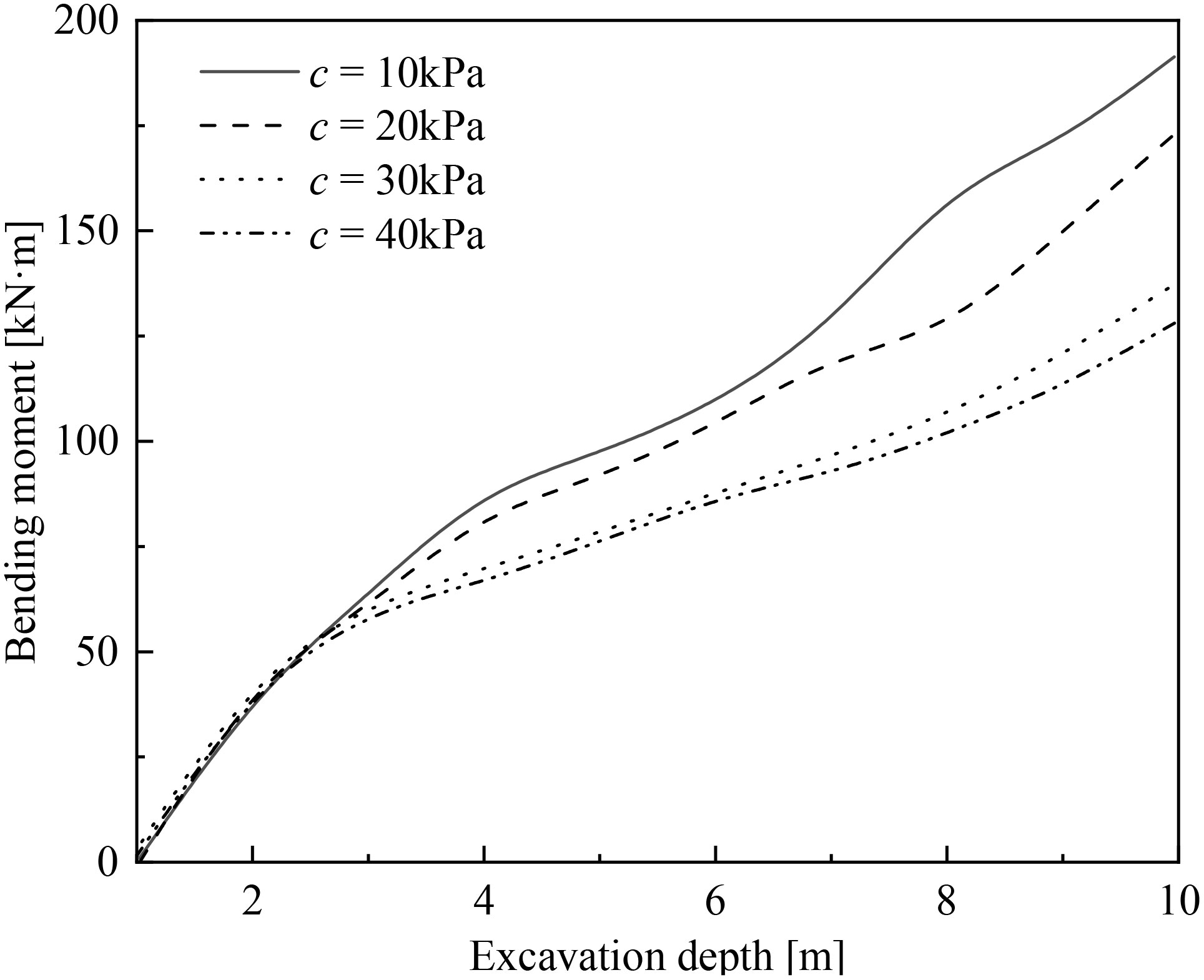
Figure 8 Effect of cohesion on pile bending moment.
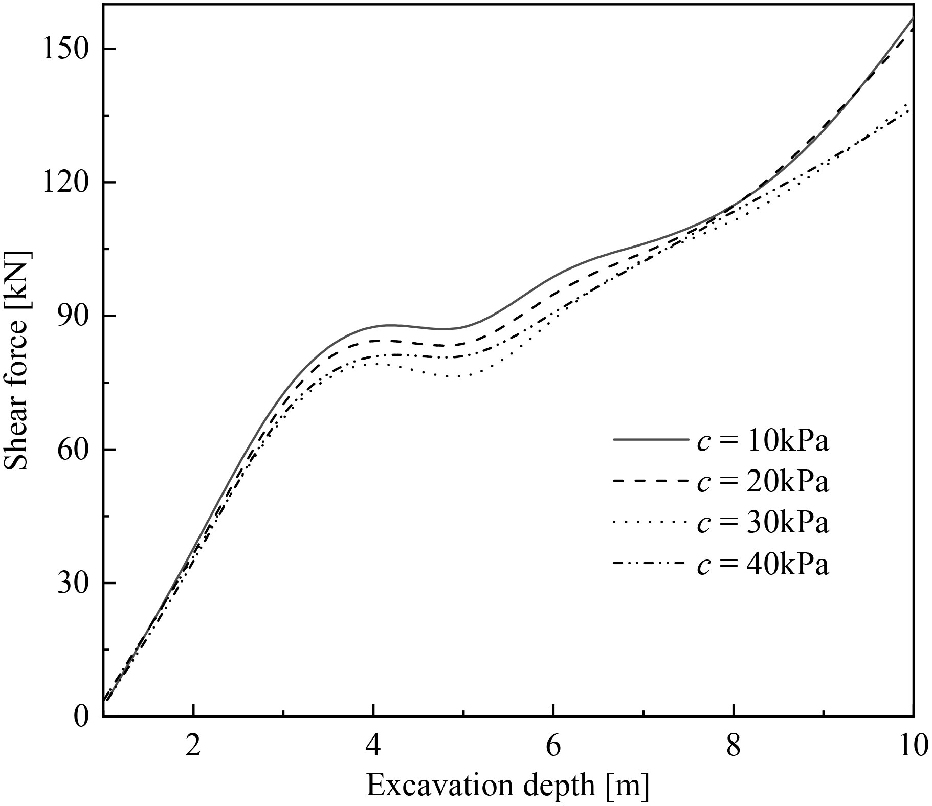
Figure 9 Effect of cohesion on pile shear force.
From Figures 10, 11, it can be seen that under different values of the internal friction angle of the soil, as the excavation depth of the foundation pit increases, there are significant changes in the bending moment and shear force of the pile body. Moreover, as the internal friction angle of the soil increases, the absolute values of the maximum bending moment and maximum shear force of the pile body show a gradually decreasing trend. At the same time, it is not difficult to see from the table that the absolute values of the maximum bending moment and maximum shear force corresponding to the excavation depth of 10m are the maximum values of the entire construction process, and when the friction angles are taken as 20°, 24°, 27°, and 30°, the corresponding maximum bending moment values are 256.31kN · m, 206.52kN · m, 190.22kN · m, 167.41kN · m, respectively, with differences of 19.43%, 7.89%, and 11.99%, and the maximum shear force values are 225.71kN, 189.83kN, respectively 183.94kN and 163.66kN, with a difference of 15.90%, 3.11%, and 11.03% respectively, and the absolute values of the maximum bending moment and maximum shear force of the pile body when the internal friction angle of the soil changes are generally greater than the corresponding results when the soil cohesion changes. From Figures 10, 11, it was found that as the friction angle increase, the bending moment shear force decreases.
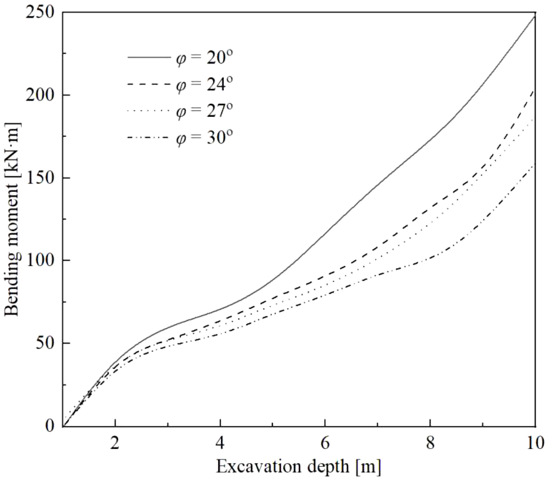
Figure 10 Effect of friction angle on pile bending moment.
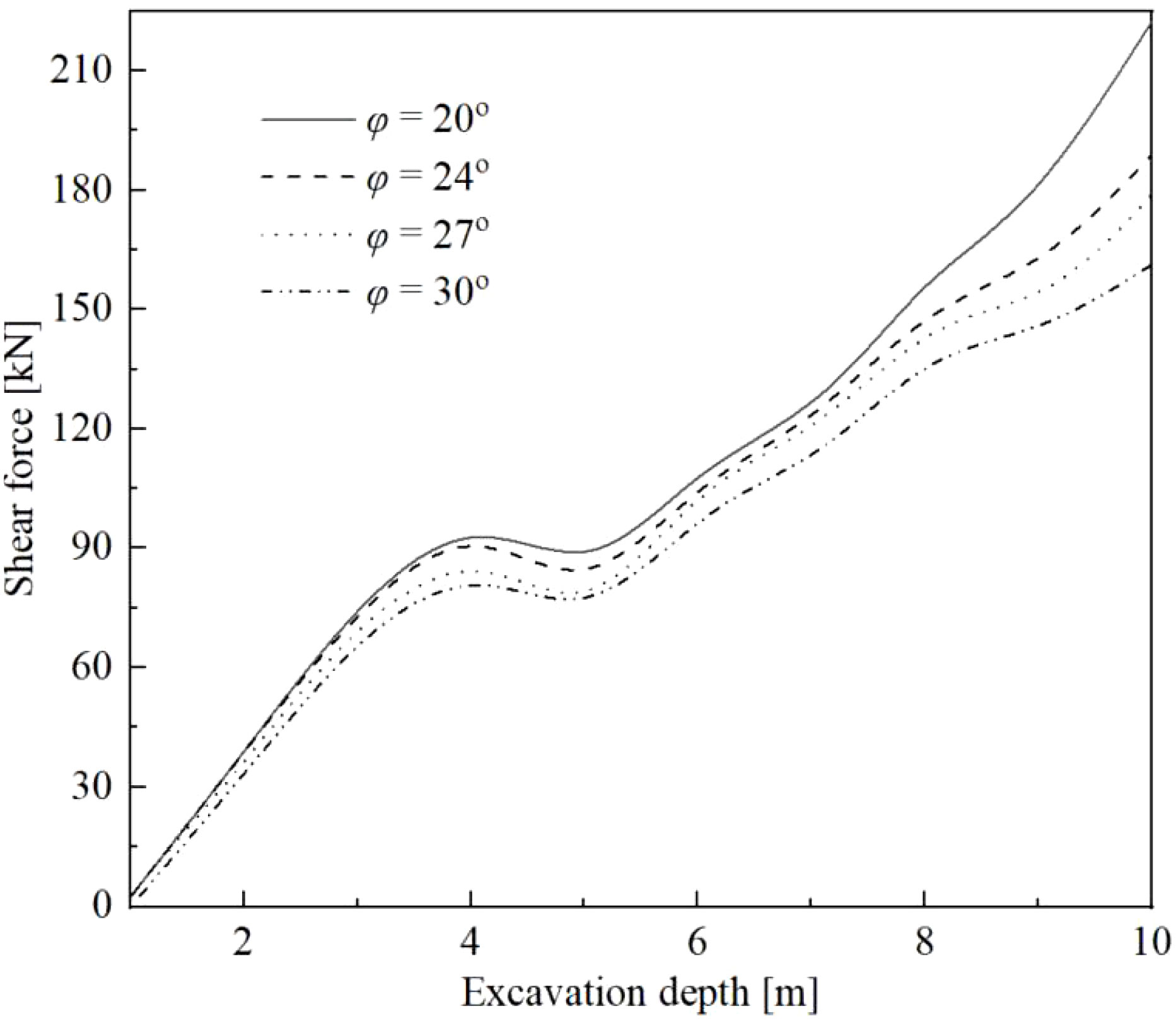
Figure 11 Effect of friction angle on pile shear force.
In this paper, a computational model is presented to quickly and accurately calculate the horizontal displacement of pile anchor support structure along the depth, taking into account the influence of anchor pre-stress in pile anchor support structure. Based on the proposed model, the main findings as follows:
1. The displacement increases with the increase of cohesion and friction angle.
2. As the cohesion and friction angle increase, the bending moment decreases. As the friction force increases, the change in bending moment is not significant.
3. As the cohesion and friction angle increase, the shear force decreases.
The original contributions presented in the study are included in the article/supplementary material. Further inquiries can be directed to the corresponding authors.
Y-QL: Conceptualization, Writing- Original draft preparation. LS: Methodology. JH: Verify, X-LC: Supervision. X-HY: Software. All authors contributed to the article and approved the submitted version.
This work was supported by the Key research and development project of Jiangsu Province, (No.2021GJZPY15); Gansu Provincial Science and Technology Commissioner Special (22CX8GA112).
The authors declare that the research was conducted in the absence of any commercial or financial relationships that could be construed as a potential conflict of interest.
All claims expressed in this article are solely those of the authors and do not necessarily represent those of their affiliated organizations, or those of the publisher, the editors and the reviewers. Any product that may be evaluated in this article, or claim that may be made by its manufacturer, is not guaranteed or endorsed by the publisher.
Chen A., Wang Q., Chen Z., Chen J., Chen Z., Yang J. (2021). Investigating pile anchor support system for deep foundation pit in a congested area of Changchun. Bull. Eng. Geology Environ. 80, 1125–1136. doi: 10.1007/s10064-020-01985-7
Fu W. C., Hong L. C. (2011). Filed test studies on internal force of pile in pile-anchor supporting system for deep foundation pit. Adv. Mater. Res. 383–390, 7713–7717. doi: 10.4028/WWW.SCIENTIFIC.NET/AMR.383-390.7713
Gao X., Tian W., Zhang Z., Li J., Qi H., Bergillos R. J. (2020). Simulation parameter test and seepage effect analysis of pile-anchor support for binary slope. Adv. Civil Eng. 2020, 1–20. doi: 10.1155/2020/8862163
Han J. H., Wang J. P., Gu C. Y. (2021). Study on the interaction mechanism between deep displacement of soil and internal force of anchor cable under pile-anchor support system of ultra-deep foundation pit. J. Physics: Conf. Ser. 1904 (1), 1–9. doi: 10.1088/1742-6596/1904/1/012019
Kung G. T., Juang C. H., Hsiao E. C., Hashash Y. M. (2007). Simplified model for wall deflection and ground-surface settlement caused by braced excavation in clays. J. Geotechnical Geoenvironmental Eng. 133 (6), 731–747. doi: 10.1061/(ASCE)1090-0241(2007)133:6(731
Li X., Xu R., Yang W., Li P., Yang K., Zhang W. (2020). Experimental study on distribution of landslide thrust in pile-anchor structure based on photoelastic technique. Materials 13 (6), 1–13. doi: 10.3390/ma13061358
Lin Q. B., Sun Y. S., Li Z. M. (2022). Analysis of deep foundation pit pile-anchor supporting system based on FLAC3D. Geofluids 1699292, 1–19. doi: 10.1155/2022/1699292
Liu L., Wu R., Congress S. S. C., Du Q., Cai G., Li Z. (2021). Design optimization of the soil nail wall-retaining pile-anchor cable supporting system in a large-scale deep foundation pit. Acta Geotech. 16, 2251–2274. doi: 10.1007/S11440-021-01154-4
Liu J. B., Xu Q. (2011). Numerical simulation research for stress and distortion of pile-anchor support structure of the deep foundation. Adv. Mater. Res. 1269 (243-249), 23128–23131. doi: 10.4028/www.scientific.net/AMR.243-249.3128
Peng H., Xiao Q. X., Dong Y. Z. (2014). Study on deformation influence of deep foundation pit pile-anchor supporting system nearby metro structure. Appl. Mechanics Materials 3489 (638-640), 1190–1194. doi: 10.4028/www.scientific.net/AMM.638-640.1190
Poulos H. G., Davis E. H. (1974). Elastic solutions for soil and rock mechanics (New York: John Wiley & Sons, Inc.), 21–34.
Saleem M. (2015). Application of numerical simulation for the analysis and interpretation of pile-anchor system failure. Geomechanics Eng. 9 (6), 689–707. doi: 10.12989/gae.2015.9.6.689
Sun Y. S., Li Z. M. (2022a). Study on design and deformation law of pile-anchor support system in deep foundation pit. Sustainability 14 (19), 12190–12190. doi: 10.3390/SU141912190
Sun Y. S., Li Z. M. (2022b). Analysis of deep foundation pit pile-anchor supporting system based on FLAC3D. Geofluids. 2022, 1–19. doi: 10.1155/2022/1699292
Wang H. (2021). Effect of genetic algorithm in optimizing deep foundation pit supporting structure. Arab. J. Geosci. 14 (4), 1–6. doi: 10.1007/S12517-021-06602-9
Xu R., Xu Y., Cheng K., Feng S. Y., Shen S. (2020). Non-limit active earth pressure solution considering soil arch effect under finite soil mass. Rock Soil Mechanics 42 (02), 362–371.
Yin Q., Fu H. L. (2023). Analysis of foundation pit excavation deformation and parameter influence of pile-anchor-ribbed-beam support system. Appl. Sci. 13 (4), 2379. doi: 10.3390/app13042379
Yin Q., Fu H. L., Liu Y. S. (2016). Anchor tension calculation for the special pile anchor supporting structure in a deep foundation pit. J. Residuals Sci. Technol. 13 (8), 1–15.
Zheng Y., Hu Z., Ren X., Wang R., Zhang E. (2021). The influence of partial pile cutting on the pile-anchor supporting system of deep foundation pit in loess area. Arab. J. Geosci. 14 (13), 1–12. doi: 10.1007/S12517-021-07560-Y
Keywords: pile anchor support structure, prestress, additional stress, horizontal displacement, theoretical analysis
Citation: Ling Y-q, Song L, Hao J, Cao X-l and Yang X-h (2023) Analytical analysis for horizontal displacement of pile anchor support structure considering prestress. Front. Ecol. Evol. 11:1249239. doi: 10.3389/fevo.2023.1249239
Received: 28 June 2023; Accepted: 14 August 2023;
Published: 18 September 2023.
Edited by:
Shaobo Chai, Chang’an University, ChinaReviewed by:
Yijie Sun, Nanjing Tech University, ChinaCopyright © 2023 Ling, Song, Hao, Cao and Yang. This is an open-access article distributed under the terms of the Creative Commons Attribution License (CC BY). The use, distribution or reproduction in other forums is permitted, provided the original author(s) and the copyright owner(s) are credited and that the original publication in this journal is cited, in accordance with accepted academic practice. No use, distribution or reproduction is permitted which does not comply with these terms.
*Correspondence: Jian HAO, c2tkaGFvamlhbkBzZHVzdC5lZHUuY24=; Xiao-lin CAO, eGxjYW9AbHV0LmVkdS5jbg==
Disclaimer: All claims expressed in this article are solely those of the authors and do not necessarily represent those of their affiliated organizations, or those of the publisher, the editors and the reviewers. Any product that may be evaluated in this article or claim that may be made by its manufacturer is not guaranteed or endorsed by the publisher.
Research integrity at Frontiers
Learn more about the work of our research integrity team to safeguard the quality of each article we publish.