 Ahsan Naseem
 Wajahat Sammer Ansari
 Muhammad Kashif3
94% of researchers rate our articles as excellent or good
Learn more about the work of our research integrity team to safeguard the quality of each article we publish.
Find out more
ORIGINAL RESEARCH article
Front. Environ. Sci. , 28 August 2023
Sec. Environmental Informatics and Remote Sensing
Volume 11 - 2023 | https://doi.org/10.3389/fenvs.2023.1242296
This article is part of the Research Topic Advances in Development and Utilization of Underground Space, volume II View all 13 articles
Tunnel construction in soft soil necessitates a thorough evaluation of soil behavior, embedment depth, ground heaves, and tunnel distortions, especially in earthquake-prone areas. This study presents a numerical parametric investigation of an unconventional tunnel complex formed by combining the closely located twin tunnels. The complex is subjected to varying horizontal ground vibrations, and the influence of lining thickness, embedment depth, and interface conditions on seismic-induced thrusts, shear forces, bending moments, tunnel distortions, and ground heaves is assessed. The applicability of analytical solutions from existing literature for singular tunnels is examined through detailed analyses of different embedment ratios. The study reveals that increased tunnel flexural rigidity leads to higher seismic-induced bending moments in the tunnel complex. Comparison of full-slip and no-slip interface conditions shows that the former exhibits reduced overall tunnel distortions. Furthermore, a comparison is made with a conventional-shaped rectangular tunnel complex. The results indicate that the twin tunnel complex behaves more rigidly under a constant embedment ratio and input motion amplitude. It also results in lower ground heaves and suffers lesser induced lining forces during seismic events, making it a superior performer in comparison. Overall, this research provides valuable insights into the behavior of twin tunnel complexes in soft soil under seismic conditions, showcasing their advantages over conventional shaped tunnels in terms of tunnel distortions, ground heaves, and overall structural response.
Tunnel construction is becoming the need of urban areas to cater to the higher traffic demands. Underground tunnels provide the benefit of uninterrupted traffic flow in areas where surface construction is not possible while keeping the surrounding area compact. Many cities are now planning and constructing underground tunnels. Apart from the singular tunnel, multiple tunnels including the twin tunnel and triplet tunnel complexes are also under consideration now. However, tunnels require extra attention when planned in an earthquake-prone area. It makes them more vulnerable to excessive settlements, thrusts, and severe damage in case of seismic activity. The condition becomes worse when the tunnels are lying in soft soil and when multiple tunnels lie close to each other. The literature explains that the major earthquakes of the past like the Kobe earthquake (Japan, 1995), the Loma Prieta earthquake (United States, 1989), and Chi-Chi earthquake (Taiwan, 1999) have caused severe damage to underground structures. The damage depends on the type of soil, groundwater condition, embedment depth of the tunnel, lining thickness of the tunnel, amplitude, duration of the earthquake, etc.
In the past, less attention was given to the effects of an earthquake on the tunnels, but the damages caused during major earthquakes have caused researchers to study this aspect as well. Many researchers are now working on the evaluation of the seismic response of tunnels analytically (Hoeg (1968), Wang (1993), Penzien (2000), Bobet (2003), Park et al. (2009), Bobet (2010), experimentally (Adalier et al., 2003; Lanzano, 2009; Lanzano et al., 2010; Bilotta et al., 2014; Ulgen, Saglam, and Ozkan, 2015), and numerically (Hashash et al., 2010; Sandoval and Bobet, 2017; Tsinidis, 2017; Sadiq et al., 2019; Naseem et al., 2020). Sharma and Judd (1991) studied the effect of the type of the soil medium and the embedment of the tunnel on seismic behavior. The study concluded that the tunnels in soft soil are more vulnerable than those in dense soil or rock. Similarly, shallower tunnels suffer more damage than deeper ones. Power et al. (1998) studied the effect of earthquake acceleration on the tunnels and found that the tunnels suffer very little damage for the peak ground acceleration (PGA) of 0.2 g while slight-to-heavy damage for PGA greater than 0.2 g. Penzien (2000), Wang (1993), and Anderson (2008) studied the seismic-induced thrusts and bending moments in tunnels and developed closed-form solutions for rectangular and circular tunnels. Chen et al. (2012) performed the numerical simulation of shake table tests and reported that the most affecting parameters in the case of mountain tunnels are embedment depth, lining thickness, distance from the epicenter, and amplitude of the seismic vibrations. Owen and Scholl (1981) studied the effect of PGA on rock tunnels and concluded that a PGA less than 0.4 g results in very slight damage. Cilingir and Madabhushi (2011c, b, a) performed centrifuge modeling to study the dynamic and post-earthquake behavior of rectangular and circular tunnels in sand and found out that after some vibrations, tunnels achieve dynamic equilibrium after which the earth pressures oscillate at a residual value around the tunnel lining. Yang et al. (2004) performed centrifuge tests to study the internal forces generated in the tunnel lining during the seismic activity. Chen and Shen (2014) recorded the seismic-induced bending moments, while Cao and Huang (2010) installed the strain gages in centrifuge tests to study the strains developed during the dynamic vibrations. Qiu et al. (2017) studied the dynamic behavior and interaction of twin tunnels in loess using centrifuge modeling to evaluate the optimum space and other tunnel parameters. Apart from experiments, numerical modeling has also been used to evaluate the dynamic behavior of tunnels. Tsinidis (2017) performed a detailed numerical parametric study on rectangular tunnels in soft soil to evaluate the forces developed in the tunnel lining, structure–ground interaction, and dynamic earth pressures. Chang, Travasarou, and Chacko (2008) evaluated the liquefaction-induced uplift of immersed tunnels using both centrifuge and numerical analyses. Azadi et al. (2010) numerically studied the uplift and the developed pore pressures of tunnels in liquefiable soils. Patil et al. (2018) performed the parametric numerical study of shallow circular tunnels in soft soils under horizontal ground shaking to evaluate tunnel forces, the effect of vibration’s amplitude, etc. However, all the available literature consists of studies on rectangular and circular tunnels, either singular or in pair located in a close proximity. The seismic behavior of the combined multiple tunnels, leading to unconventional shapes, has not been studied.
This study evaluates the seismic performance of the twin tunnel complex which is an unconventional shape resulting from the combination of two closely located circular tunnels and one of the novel tunnel shapes that have been hypothetically proposed to carry multiple underground railway tracks. This research is divided into different parts. In the first part, the construction arrangement for different configurations of closely spaced multiple tunnels has been studied in terms of the produced ground settlements (Naseem et al., 2019). In the second part, three closely spaced circular tunnels combined into a novel triple tunnel complex have been parametrically estimated and compared to the equivalent rectangular tunnel complex (Naseem et al., 2020). This paper parametrically evaluates the behavior of a twin tunnel complex in soft soil, numerically using finite element (FE) software PLAXIS 2D. The study evaluates the effect of amplitude, embedment depth, and lining thickness on structural distortions, lateral pressures, and seismic-induced lining forces. A comparison is also made with the equivalent conventional-shaped rectangular tunnel complex to identify the better performer between the two.
This study is carried out using the dynamic module of PLAXIS 2D which is a finite element (FE) software. It is capable of performing analyses on various types of soil types. The constitutive models available include hardening soil (HS), hardening soil with small strains (HSsmall), concrete, and Mohr–Coulomb (MC) (Brinkgreve et al., 2010). This study is performed using the MC model. As it is an elastic-perfectly plastic model, to be able to use it for dynamic analyses, PLAXIS 2D makes use of the modified MC model. The input parameters, i.e., elastic modulus (E) and shear modulus (G), for the model are calculated for each soil layer based on its shear wave velocity (Vs). Apart from this, the variation in the moduli with respect to depth is also taken into account.
Seismic vibrations produce cyclic stresses, developing the hysteric loop with energy dissipation and damping. As the MC model is incapable of capturing this phenomenon, so to cater to this, frequency-dependent Rayleigh viscous damping parameters are incorporated in the model. The equations are given as
While
where α and β are the Rayleigh viscous damping coefficients, ω1, and ω2 are the angular frequencies, h is the thickness of the soil layer, Vs represents the shear wave velocity for the respective soil layer, f1, and f2 are the first and second target frequencies, and ξ1 and ξ2 are the respective damping ratios which are taken as 10% for soft soil.
The layered soil system is used in this study. The top layer is silty clay which is followed by very soft silty clay and soft clay, underlain by clay and silty clay–silty sand layers. The soil system is categorized as soft soil type D according to Eurocode 8 (Code, 2005). The detailed geotechnical soil parameters are tabulated in Table 1, while the Vs profile with respect to the depth is given in Figure 1D. The ground conditions are considered fully saturated with the groundwater table (GWT) at the surface. The benefit of using a layered soil profile is to include the effect of variation of Vs along the depth as well as the different soil properties on the tunnel’s C/H ratio. This is the same layered soil as previously used by Huo et al. (2005), Naseem et al. (2020), and Patil et al. (2018).
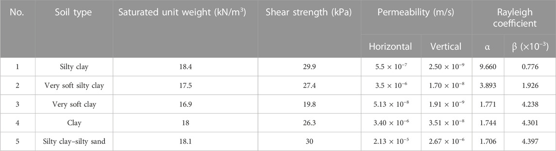
TABLE 1. Soil properties used in the study.
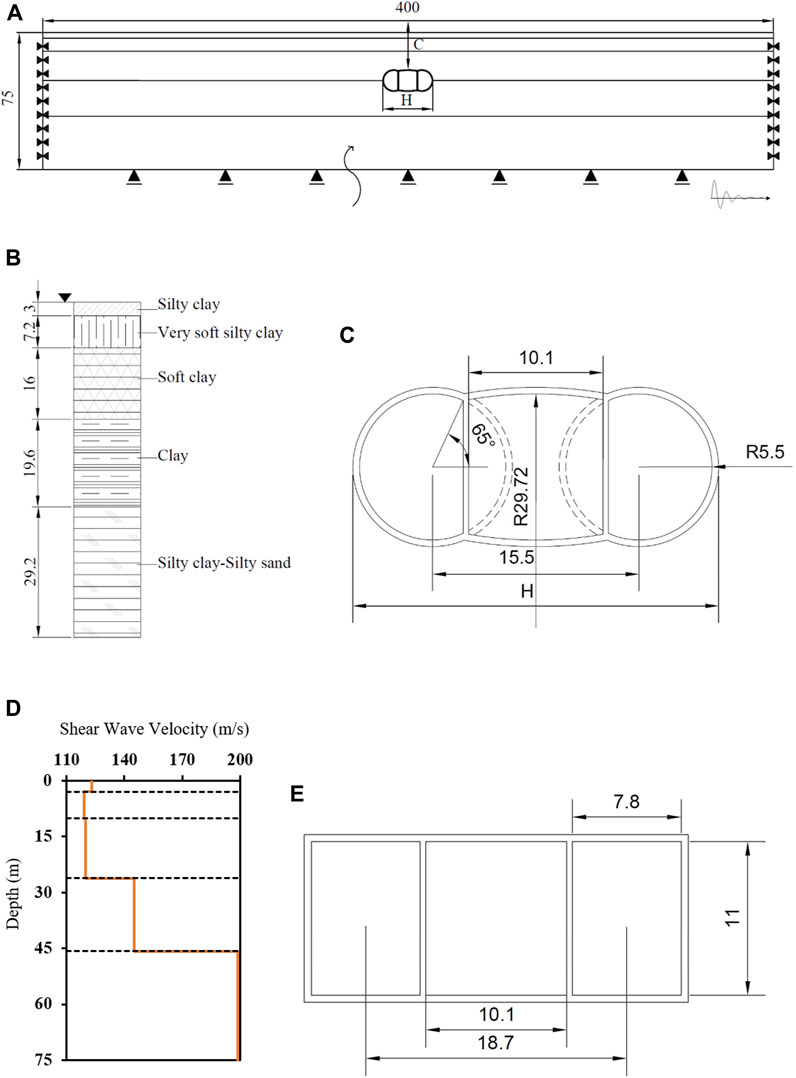
FIGURE 1. Soil–tunnel geometry (A). Soil layers with the embedded triple tunnel complex (B). Soil column with respect to the depth and type (C). Enlarged twin tunnel complex section, also showing the truncated parts (units in “m”) (D). Shear wave velocity profile with respect to depth (E) Equivalent rectangular tunnel complex with dimensions (units in “m”).
The 2D plane strain numerical model with 15-noded triangular elements is used, with the tunnel lining elements being considered the elastic plate elements. The elastic modulus of the liner (El) is taken as 37 GPa, while the unit weight as 25 KN/m3, and the Poisson’s ratio (υl) as 0.2. The detailed layered soil profile along with the tunnel geometry can be seen in Figures 1A–C. The tunnel width (H) and embedment depth (C) are kept as variables to study the effect of the embedment ratio (C/H) on the overall tunnel seismic behavior. The dimensions of the model are kept at 400 × 75 m. The boundaries of the model are so kept that they do not interfere with the wave propagation. The free-field boundaries are considered at the lateral ends to absorb the incident waves, while the bottom boundary is considered to be fully reflective. The mesh size is selected based on the Kuhlemeyer et al. (1973) equation so that the wave does not pass one element per single time step.
And
where Δl is the length of the finite elements and λ is the wavelength, Vs is the least shear wave velocity, and f is the frequency. The time step also plays an important role in the overall accuracy of the results and hence is selected as
where δt is the time step, t is the total time duration of the seismic vibration, and Δt is the sub-step.
The major earthquakes in history are used to evaluate the seismic performance and design the structures in earthquake-prone regions. This study includes three earthquakes from the past. The Kocaeli (Turkey, 1999) earthquake, the Coyote (United States, 1979), and the Kobe (Japan, 1995) earthquake signals are applied to the tunnel–soil system to evaluate the seismic performance. The input motions (IMs) are scaled to the amplitude of 0.4 g for using them in this study. The details of the earthquake records are tabulated in Table 2, while the acceleration–time histories and Fourier amplitudes are given in Figures 2A–C. The normalized spectral acceleration curves plotted with the Eurocode 8 site class A can be seen in Figure 2D.
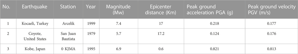
TABLE 2. Records of earthquake vibrations.
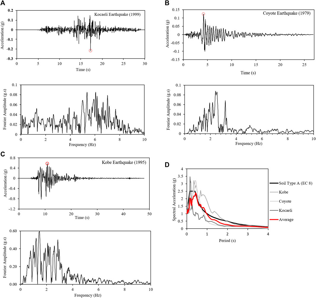
FIGURE 2. Acceleration–time history and the Fourier amplitude of (A) Kocaeli earthquake (1999), (B) Coyote earthquake (1979), and (C) Kobe earthquake (1995). (D) Comparison of the normalized spectral accelerations with the design spectrum of site class A (EC8).
This research studies an unconventional tunnel complex for which experimental data and specific analytical solutions are not available. To verify that the produced results by PLAXIS 2D are acceptable, a validation study is performed. A circular tunnel of 6 m diameter is considered in the same layered soil profile (Table 1) with no-slip conditions at the soil–structure interface (SSI) and the Kobe earthquake with 0.4 g amplitude is applied to the model. The lining thickness varies from 0.1 to 1 m to have a wide range of flexibility ratios (Table 3). The obtained shear strains from the 1D soil column analysis are converted to the pseudo-static displacements and applied to the soil–tunnel system to compute the lining forces. The calculated numerical values are then compared with the analytical solutions of Wang (1993), Penzien (2000), and Bobet (2010) tabulated in Table 4. The results can be seen in Figures 3A, B, which are in close agreement, hence depicting that the obtained numerical values are accurate. A similar type of a validation study was also conducted by Patil et al. (2018) and Naseem et al. (2020).
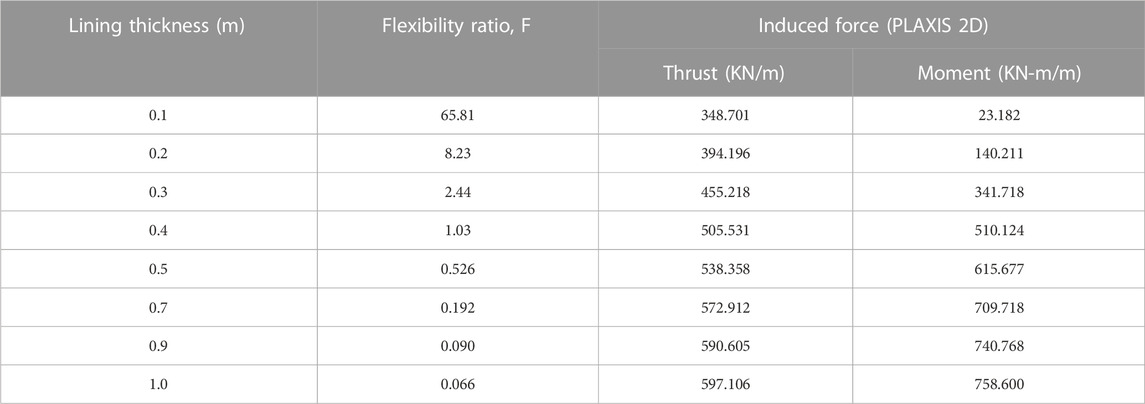
TABLE 3. Tunnel lining thicknesses and induced thrusts and bending moments.
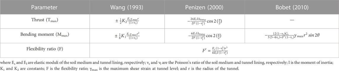
TABLE 4. Analytical solutions to calculate induced thrusts and moments.

FIGURE 3. Comparison between numerical and analytical solutions: (A) thrust and (B) bending moment.
In this research, a detailed numerical parametric study is performed to evaluate seismic performance. The effect of variation in lining thickness, C/H ratio, and the amplitude of the seismic vibrations are studied to evaluate the produced ground deformations, tunnel distortions, seismic-induced thrusts, shear forces, and bending moments. An equivalent rectangular tunnel complex (Figure 1E) is also analyzed, and a detailed comparison is then made to evaluate the overall performance.
The analytical solutions to calculate the flexibility ratio (F) that are available in the literature are for singular tunnels. To find their applicability to the combined circular twin tunnel complex, detailed dynamic analyses are performed by varying the tunnel lining thickness from 0.1 to 1.5 m to calculate the ratio of distortions in free-field (FF) and the tunnel complex. Three C/H ratios, i.e., 0.25, 0.5, and 0.75, are considered for this study. The F is obtained from the ratio of soil deformations (obtained using PLAXIS 2D) and structural deformations (obtained using the structural analyses program). The normalized tunnel distortions are also calculated using the closed-form solutions by Wang (1993), Penzien (2000), and Anderson (2008), and the results from the numerical and analytical methods are compared, which can be seen in Figures 4A–C. From the figures, it can be noticed that there is some minor difference between the numerically and analytically obtained values which is because the numerical analyses are performed taking into consideration the nonlinear behavior of soil, while the analytical solutions are developed considering the linear elastic behavior. The overall results are in good agreement with the analytical solutions; hence, they can be used to calculate the normalized structural distortions and F for the combined circular twin tunnel complex.
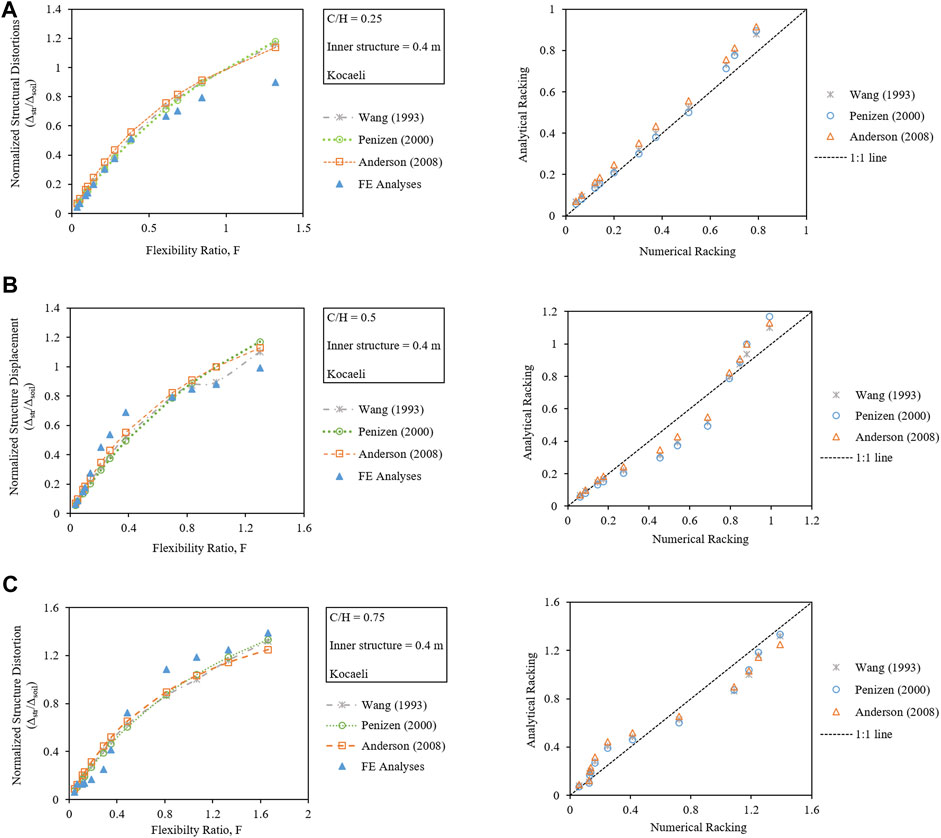
FIGURE 4. Validation of analytical R–F relationships for C/H ratios: (A) 0.25, (B) 0.5, and (C) 0.75.
To study the variation in lining thickness, twin tunnel complexes with different lining thicknesses varying from 0.12 to 2 m are seismically analyzed. The range is so selected that it covers both flexible and rigid tunnels. All the other parameters, i.e., the C/H ratio, the amplitude of the IM, and the thickness of the inner structure, are kept constant. The thickness variation in the tunnel is represented in terms of F, and their relationship is represented in Figure 5A. From the figure, it can be observed that the tunnel section of approximately 0.15 m thickness is the critical section having F ≈ 1.
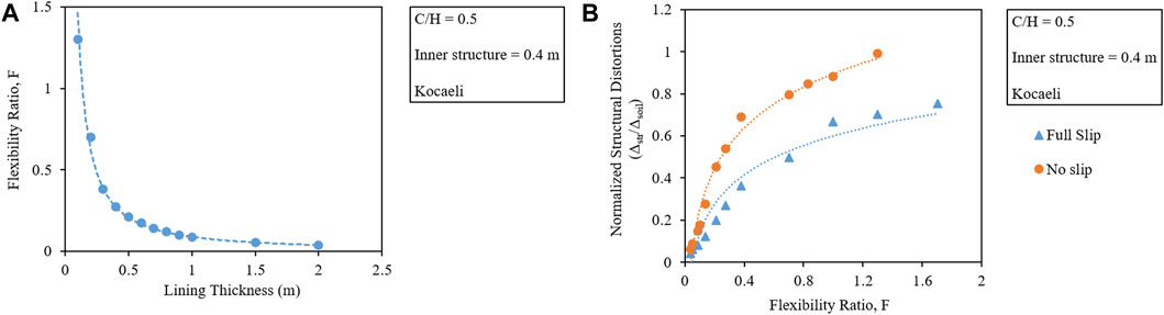
FIGURE 5. (A) Lining thickness representation in terms of flexibility ratios. (B) Comparison of tunnel distortions for full-slip and no-slip interface conditions.
To study the tunnel distortions, both full-slip (μ = 1) and no-slip (μ = 0) cases are considered. From Figure 5B, it can be seen that the normalized tunnel distortions increase with the flexibility of the tunnel lining, while the same thickness of tunnel lining would undergo more distortions in case of no-slip condition as compared to when the slip is present in between the tunnel–soil interface. The reason is that the full slip allows for easier movements and rotation within the soil, hence reducing the distortions, which are in line with the results obtained by Tsinidis (2017) and Debiasi, Gajo, and Zonta (2013).
The produced ground deformations and seismic-induced forces (thrusts, shear forces, and bending moments) can be seen in Figures 6A–D, respectively. From the surface displacement curve, it can be noticed that the increased thickness of the tunnel lining makes the tunnel behave as rigid and results in lesser ground heave because the tunnel would resist the distortions produced by seismic vibrations, resulting in lesser seismic-induced thrusts (T) and more shear forces (Q) and bending moments (M). As the F ≥ 1, the tunnel behaves almost like the soft soil medium; hence, the induced T and Q get excessively large and the M is reduced to the minimum as the capacity to resist is sufficiently reduced. These results are similar to those obtained by Azadi et al. (2010) and Abdel-Motaal, El-Nahhas, and Khiry (2014). Hence, to increase the tunnel resistance, reinforcement should be increased instead of providing thicker tunnel linings, as recommended by Hashash et al. (2001).

FIGURE 6. Variation in (A) surface displacements and seismic-induced (B) thrusts, (C) shear force, (D) and bending moments in a combined twin tunnel complex of varying F.
The induced forces in the internal connection members can be seen in Figures 7A, B. From the figures, it can be observed that the induced Q and M in the tunnel lining also have an impact on the forces generated in the internal connecting members. With a decrease in the F of the tunnel, the tunnel lining becomes stiff and more forces are taken up by it, resulting in lesser forces in the internal members, and hence the reduced dimensions of the members. On the contrary, if the tunnel structure is more flexible, the stability of the tunnel complex would be relying more on the internal connecting members as more forces will be generated in the internal connecting members, and hence will lead to the thicker dimensions of the internal members.
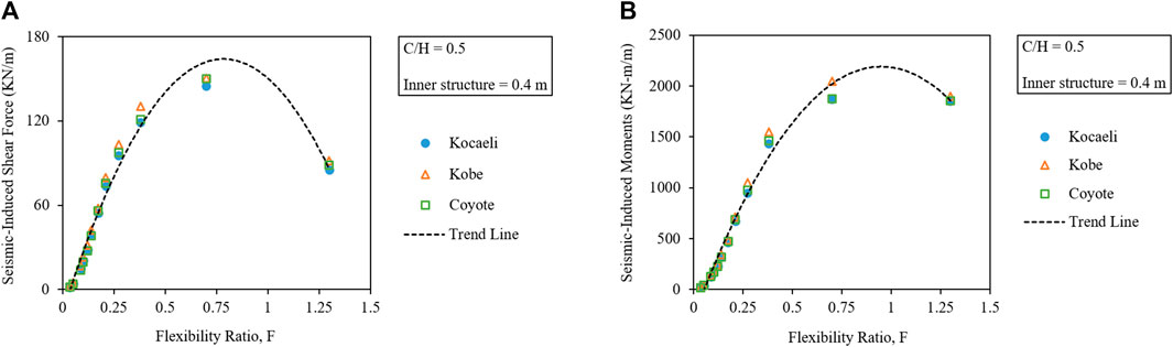
FIGURE 7. Variation in seismic-induced (A) shear forces and (B) bending moments in connecting members of a combined twin tunnel complex of varying F.
To study the effect of variation in C/H, the lining thickness, the amplitude of the IM, and the thickness of the inner structure are kept constant. Three C/H ratios, i.e., 0.25, 0.5, and 0.75, are studied in this regard that produced ground deformations, and normalized tunnel distortions are plotted, which can be seen in Figure 8. The figure shows that although negligible but there are lesser structural distortions in case of the C/H ratio of 0.75 for F < 0.5. The reason is that for F ≤ 0.5, the lining thickness is more than the inner connecting members; hence, embedment depth contributes to lesser distortions. As the lining thickness decreases than the inner members, the overburden pressure results in the buckling and collapse of inner structures, and thus results in more structural distortions. This explanation is corroborated by the drastically increasing seismic-induced M, Q, and T beyond the F of 0.5 plotted in Figures 5–7. From the obtained trendlines, it is evident that as the C/H ratio increases, the tunnel behaves more flexibly and undergoes increased tunnel distortions.
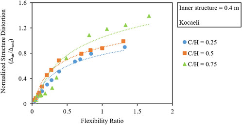
FIGURE 8. Effect of variation in the embedment depth on normalized tunnel deformations.
While keeping the lining thickness, C/H ratio, and thickness of the inner structure constant, the amplitude of input motion (IM) is varied from 0.1 g to 0.5 g. The variation in the settlement trough along the width, maximum produced ground displacements, and seismic-induced lining forces with respect to the amplitude for the three IMs is plotted in Figures 9A–E. From the figures, it can be seen that the increased amplitude of IM results in exponentially increased ground heaves, and also a logarithmic increase in the seismic-induced lining forces. The obtained results show a similar trend as those obtained by Azadi et al. (2010) and Patil et al. (2018).
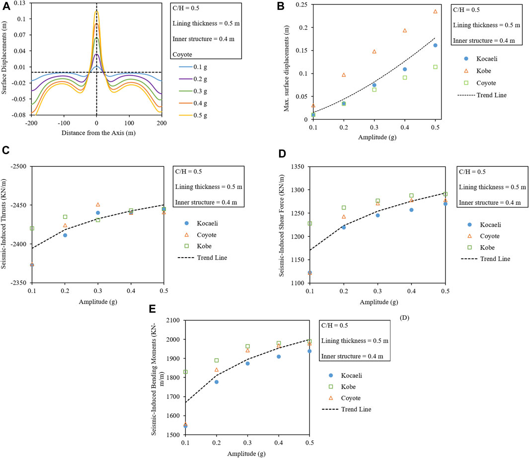
FIGURE 9. Comparison of (A) surface displacement troughs to the variation in amplitude (B), maximum ground displacements and seismic-induced maximum (C) thrusts, (D) shear forces, and (E) bending moments with respect to the amplitude of three IMs.
The residual earth pressures from the dynamic analyses are also calculated, which can be seen plotted along with the normalized tunnel perimeter (given in Figures 10B, C) and the deformed tunnel complex shape in Figure 10A. The figures show that the higher amplitude vibrations result in higher uplift pressures on the tunnel structure. This phenomenon causes the dynamic earth pressure to decrease at the invert (0) and on the crown (0.5) due to the heaving of soil and increase on the side walls (0.25 and 0.75) and the shoulder parts (0.3125 and 0.6875) due to the densification and inward movement of the surrounding soil to fill up the void with the increase in the amplitude of the seismic vibration.
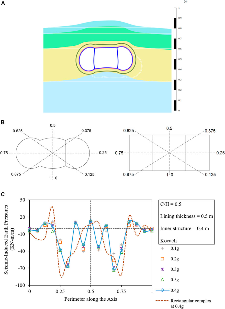
FIGURE 10. (A) Deformed complex under the seismic vibrations (50 x zoom). (B) Normalized tunnel perimeter for the circular twin and rectangular tunnel complex. (C) Variation in residual earth pressures with respect to the amplitude along with the circular twin tunnel perimeter and comparison with the rectangular tunnel complex.
The evaluation of seismic-induced T, Q, and M is very important to understand the distribution of forces along the tunnel lining, which helps in the optimum design of the tunnel structure. To evaluate the forces, the circular twin tunnel complex is subjected to the selected acceleration–time histories while keeping the C/H ratio, the thickness of the lining, and internal connection members constant. The detailed T, Q, and M diagrams can be seen in Figures 11A–C.
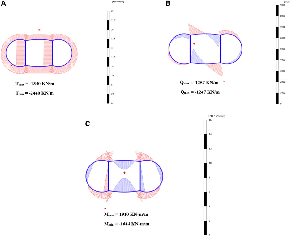
FIGURE 11. Seismic-induced (A) thrusts, (B) shear forces, and (C) bending moments in the circular twin tunnel complex.
Apart from this, the variation in the induced forces along with the tunnel perimeter is also plotted for each of the IMs, which can be seen in Figures 12A–C. The figures show that the critical sections are the invert (0 and 1) and the crown (0.5) which suffer the maximum M, while the knee portions (0.125 and 0.875) are other important sections suffering the maximum T.
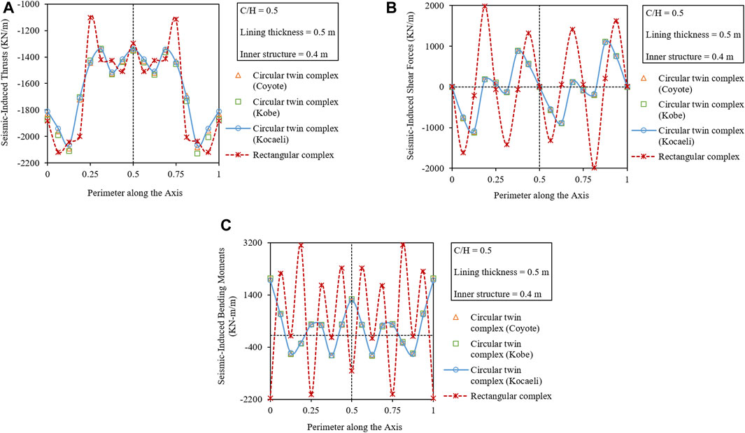
FIGURE 12. Variation in seismic-induced (A) thrusts, (B) shear forces, and (C) bending moments along the perimeter of the circular twin tunnel complex and comparison with the rectangular tunnel complex.
To better understand the seismic performance of the twin tunnel complex, it is compared with the conventional equivalent rectangular tunnel complex (given in Figure 1E).
The obtained F and the normalized tunnel distortions with respect to the thickness of the tunnel lining are plotted together for both the tunnel complexes, which can be seen in Figures 13A, B, respectively. All the other affecting parameters, i.e., the C/H ratio, IMs, and the thickness of the internal connecting members, are kept constant.
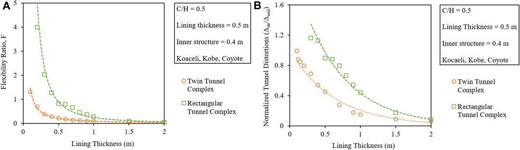
FIGURE 13. Comparison of lining thickness with the (A) flexibility ratio. (B) Normalized tunnel distortions for circular twin and rectangular tunnel complexes.
From the figures, it can be observed that the critical section of the twin tunnel complex (F = 1) has a lining thickness of approximately 0.15–0.2 m, while the rectangular tunnel complex has a lining thickness of approximately 0.45–0.5 m. It means that the same lining thickness would result in a rigid circular twin tunnel complex as well as a flexible rectangular tunnel complex.
The variation in surface displacement trough along the section width and maximum displacements for both the tunnel complexes are evaluated with respect to the varying amplitude of IMs by keeping the C/H ratio and the thickness of the internal connecting members constant. The obtained plots can be seen in Figures 14A–D. From the figures, it can be noticed that the circular twin tunnel complex results in lesser ground displacements than the equivalent rectangular tunnel complex.
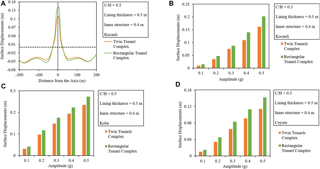
FIGURE 14. Comparison of (A) surface displacement troughs along the width and the produced maximum ground displacements with respect to the varying amplitude of (B) Kobe, (C) Coyote, and (D) Kocaeli earthquakes.
From the comparison, it can be noticed that the twin tunnel is rigid between the two for the given lining thickness and produces approximately 1.3 times lesser displacements than the rectangular tunnel complex.
The seismic-induced residual earth pressures are compared for both the tunnel complexes by plotting the variation along with the tunnel perimeter, which can be seen in Figure 10C. From the figure, it can be noticed that having the same lining thickness and other parameters, the circular twin tunnel complex undergoes approximately 1.15 times lesser earth pressures than the rectangular tunnel complex.
The seismic-induced lining forces, i.e., T, Q, and M, are compared in two different ways. One comparison is made in terms of maximum induced forces with respect to the varying tunnel lining thickness and the second in terms of the variation in induced forces along with the tunnel perimeter which can be seen in Figures 12A–C, 15A–C, respectively.
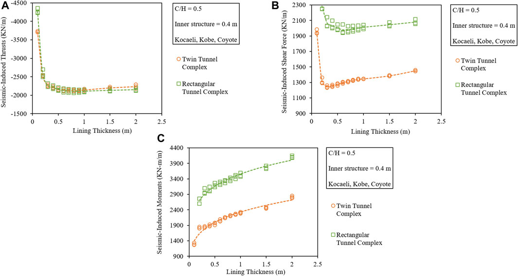
FIGURE 15. Comparison of the seismic-induced (A) thrusts, (B) shear forces, and (C) bending moments with respect to the lining thickness for the circular twin and rectangular tunnel complexes.
Figures 15A–C show that having the same C/H ratio and lining thickness, the seismic-induced forces (T, Q, and M) in the twin tunnel complex are lesser between the two complexes. From the variation of seismic-induced forces along with the normalized tunnel perimeter shown in Figures 12A–C, it can be noticed that the rectangular tunnel suffers the maximum seismic-induced forces. Furthermore, it can be noticed that the critical section in the circular twin tunnel complex is the invert (0 and 1) and the knee (0.125 and 0.875) which experience the maximum forces, but in the case of the rectangular tunnel complex, the corners and the joint sections are all critical due to larger induced forces.
Keeping the C/H ratio, the amplitude of IM, the thickness of tunnel lining, and the inner connecting members constant, the Tmax in a circular twin tunnel complex is approximately 1.03 times lesser than that of the rectangular tunnel complex. The Qmax induced in the circular twin complex is approximately 1.81 times lesser than that in the rectangular tunnel complex. The Mmax induced in the circular twin complex is approximately 1.64 times lesser than that of the rectangular tunnel complex.
This research is a preliminary study that evaluates and compares the seismic behavior of a novel twin tunnel complex with an equivalent rectangular tunnel complex in 2D. The spatial variation in the longitudinal direction along with the feasibility and practical problems associated with the construction of such a complex shape are ignored while performing this study. Hence, the effect of soil variation, presence of a fault, slope variation, etc., in the longitudinal direction should also be studied using 3D modeling for further evaluation of its seismic performance.
Tunnels being an important lifeline structure require an in-depth study when located in an earthquake-prone area to avoid damage during a seismic event. Closely spaced circular twin tunnels combined into a single circular twin tunnel complex result in a novel shape. A detailed numerical study is thus performed on this unconventional tunnel complex shape in the soft soil using three historic major earthquakes to study the effect of lining thickness, embedment depth, and variation in amplitude of seismic vibration on the overall performance. From the obtained results, it is understood that the overall behavior of the tunnel complex depends on both the tunnel lining and the inner connecting members. If the lining thickness is more than the inner structure for F ≤ 0.5, more forces are resisted by the lining than the inner structure. The suffered structural distortions are lesser because the surrounding soil pressure keeps the tunnel complex compact. On the contrary, thinner lining with thicker inner connecting members results in enormous seismic-induced forces in the inner members and hence causes severe distortions. Apart from this, the connection joints of the lining and the inner members are critical sections suffering enormous forces that may result in the collapse of the whole complex and hence need careful consideration during the design. The produced ground heaves, residual dynamic earth pressures, seismic-induced thrusts, shear forces, and bending moments are also compared with those of conventional-shaped rectangular tunnel complex. Based on the study, the following main results are concluded.
1. The increased flexural rigidity of the tunnel lining results in reduced ground heaves while also leading to the increased seismic-induced lining forces.
2. The full-slip interface conditions result in lesser tunnel distortions than the no-slip interface conditions.
3. The increased C/H ratio increases the overall normalized tunnel distortions.
4. The increase in the amplitude of the IM results in an exponential increase of the surface displacements while also leading to a logarithmic increase in the lining forces.
5. The dynamic earth pressures decrease at the invert and crown due to the ground heave and uplift phenomenon but increase at the sides because of the inward soil movement to fill in the void area due to heaving.
6. Keeping the C/H ratio and the amplitude of the IMs constant, the twin tunnel complex behaves rigidly while the rectangular tunnel complex behaves flexibly.
7. The normalized tunnel distortions in the case of a twin tunnel complex are lesser than those in the rectangular tunnel complex.
8. The twin tunnel results in lesser ground heaves and seismic-induced Q and M than the conventional equivalent rectangular tunnel complex. The overall induced T is also minimum in the case of the twin tunnel complex, which makes it a better performer during seismic vibrations.
The original contributions presented in the study are included in the article/Supplementary Material; further inquiries can be directed to the corresponding author.
AN and HD contributed to the conception. AN contributed to the design of this study, performed numerical analyses, and wrote the main manuscript draft. MK, WA, and SS reviewed and made improvements to the draft. SS, KS, and HD provided useful input and supervision. All authors contributed to the article and approved the submitted version.
The authors are thankful to Gent University (Belgium) for providing the facilities, Qilu Institute of Technology (China) to provide the funding for this particular research under the grant “QIT23TP001” and the Higher Education Commission (HEC) of Pakistan to fund this tunneling project under the grant “HRDI-UESTP/UETs Phase 1.”
The authors declare that the research was conducted in the absence of any commercial or financial relationships that could be construed as a potential conflict of interest.
All claims expressed in this article are solely those of the authors and do not necessarily represent those of their affiliated organizations, or those of the publisher, the editors, and the reviewers. Any product that may be evaluated in this article, or claim that may be made by its manufacturer, is not guaranteed or endorsed by the publisher.
Abdel-Motaal, , Ahmed, Mohamed, and Mohamed El-Nahhas, FathallaAhmed Tawfik Khiry (2014). Mutual seismic interaction between tunnels and the surrounding granular soil. HBRC J. 10 (3), 265–278. doi:10.1016/j.hbrcj.2013.12.006
Adalier, Korhan, Abdoun, Tarek, Dobry, Ricardo, Phillips, Robert, Yang, Di, and Naesgaard, Ernest (2003). Centrifuge modelling for seismic retrofit design of an immersed tube tunnel. Int. J. Phys. Model. geotechnics 3 (2), 23–35. doi:10.1680/ijpmg.2003.030203
Anderson, Donald G. (2008). Seismic analysis and design of retaining walls, buried structures, slopes, and embankments. Transp. Res. Board 611. doi:10.17226/14189
Azadi, M., Mir, S. M., and Hosseini, Mohammad (2010). Analyses of the effect of seismic behavior of shallow tunnels in liquefiable grounds. Tunn. Undergr. space Technol. 25 (5), 543–552. doi:10.1016/j.tust.2010.03.003
Bilotta, Emilio, Lanzano, Giovanni, Madabhushi, S. P. Gopal, and Silvestri, Francesco (2014). A numerical Round Robin on tunnels under seismic actions. Acta Geotech. 9 (4), 563–579. doi:10.1007/s11440-014-0330-3
Bobet, A. (2003). Effect of pore water pressure on tunnel support during static and seismic loading. Tunn. Undergr. Space Technol. 18 (4), 377–393. doi:10.1016/s0886-7798(03)00008-7
Bobet, Antonio (2010). Drained and undrained response of deep tunnels subjected to far-field shear loading. Tunn. Undergr. Space Technol. 25 (1), 21–31. doi:10.1016/j.tust.2009.08.001
Brinkgreve, R. B. J., Swolfs, W. M., Engin, E., Waterman, D., Chesaru, A., Bonnier, P. G., et al. (2010). PLAXIS 2D 2010 User manual. Delft, Netherlands: Plaxis bv.
Chang, Dongdong, Travasarou, Thaleia, and Jacob, Chacko “Numerical evaluation of liquefaction-induced uplift for an immersed tunnel,” in Proceedings of the 14th world conference on earthquake engineering, Reykjavik, Iceland, June 2008.
Chen, Zhiyi, Shi, Cheng, Li, Tianbin, and Yuan, Yong (2012). Damage characteristics and influence factors of mountain tunnels under strong earthquakes. Nat. hazards 61 (2), 387–401. doi:10.1007/s11069-011-9924-3
Chen, Z. Y., and Shen, H. (2014). Dynamic centrifuge tests on isolation mechanism of tunnels subjected to seismic shaking. Tunn. Undergr. Space Technol. 42, 67–77. doi:10.1016/j.tust.2014.02.005
Cilingir, Ulas, and Madabhushi, S. P. Gopal (2011c). A model study on the effects of input motion on the seismic behaviour of tunnels. Soil Dyn. Earthq. Eng. 31 (3), 452–462. doi:10.1016/j.soildyn.2010.10.004
Cilingir, Ulas, and Madabhushi, S. P. Gopal (2011a). Effect of depth on seismic response of circular tunnels. Can. Geotechnical J. 48 (1), 117–127. doi:10.1139/t10-047
Cilingir, Ulas, and Madabhushi, S. P. G. O. P. A. L. (2011b). Effect of depth on the seismic response of square tunnels. Soils Found. 51 (3), 449–457. doi:10.3208/sandf.51.449
Code, Euro (2005). Eurocode 8: Design of structures for earthquake resistance-part 1: General rules, seismic actions and rules for buildings. Brussels, Belgium: European Committee for Standardization.
Debiasi, E., Gajo, A., and Zonta, D. (2013). On the seismic response of shallow-buried rectangular structures. Tunn. Undergr. space Technol. 38, 99–113. doi:10.1016/j.tust.2013.04.011
Hashash, , Youssef, M. A., Hook, J. J., Schmidt, B., John, I., and Yao, C. (2001). Seismic design and analysis of underground structures. Tunn. Undergr. space Technol. 16 (4), 247–293. doi:10.1016/s0886-7798(01)00051-7
Hashash, , Youssef, M. A., Karina, Karina, Koutsoftas, Demetrious, and O'Riordan, Nick “Seismic design considerations for underground box structures,” in Proceedings of the Earth Retention Conference, Bellevue, Washington, United States, January 2010.
Hoeg, K. A. A. R. E. (1968). Stresses against underground structural cylinders. J. Soil Mech. Found. Div.
Huo, H., Bobet, A., Fernández, G., and Ramirez, J. (2005). Load transfer mechanisms between underground structure and surrounding ground: Evaluation of the failure of the daikai station. J. Geotechnical Geoenvironmental Eng. 131 (12), 1522–1533. doi:10.1061/(asce)1090-0241(2005)131:12(1522)
Kuhlemeyer, , Roger, L., and Lysmer, J. (1973). Finite element method accuracy for wave propagation problems. J. Soil Mech. Found. Div 99, 421–427. doi:10.1061/jsfeaq.0001885
Lanzano, G., Bilotta, E., Russo, G., Silvestri, F., and Madabhushi, S. P. G. “Dynamic centrifuge tests on shallow tunnel models in dry sand,” in Proceedings of the VII international conference on physical modelling in geotechnics (ICPMG 2010), Zurich, Switerland, June 2010.
Lanzano, Giovanni (2009).Physical and analytical modelling of tunnels under dynamic loadings PhD Thesis. Naples, Italy: University of Naples Federico II.
Naseem, Ahsan, Kashif, Muhammad, Iqbal, Nouman, Schotte, Ken, and De Backer, Hans (2020). Seismic behavior of triple tunnel complex in soft soil subjected to transverse shaking. Appl. Sci. 10 (1), 334. doi:10.3390/app10010334
Naseem, Ahsan, Schotte, Ken, De Pauw, Bart, and De Backer, Hans (2019). Ground settlements due to construction of triplet tunnels with different construction arrangements. Adv. Civ. Eng. 2019, 1–18. doi:10.1155/2019/8637837
Owen, G. Norman, and Scholl, Roger E. (1981).Earthquake engineering of large underground structures Washington, DC, USA: Bureau of Transportation Statistics.
Park, Kyung-Ho, Tantayopin, Kullachai, Tontavanich, Bituporn, and Owatsiriwong, Adisorn (2009). Analytical solution for seismic-induced ovaling of circular tunnel lining under no-slip interface conditions: A revisit. Tunn. Undergr. Space Technol. 24 (2), 231–235. doi:10.1016/j.tust.2008.07.001
Patil, Milind, Choudhury, Deepankar, Ranjith, P. G., and Zhao, Jian (2018). Behavior of shallow tunnel in soft soil under seismic conditions. Tunn. Undergr. Space Technol. 82, 30–38. doi:10.1016/j.tust.2018.04.040
Penzien, Joseph (2000). Seismically induced racking of tunnel linings. Earthq. Eng. Struct. Dyn. 29 (5), 683–691. doi:10.1002/(sici)1096-9845(200005)29:5<683::aid-eqe932>3.0.co;2-1
Power, M., Rosidi, D., Kaneshiro, J., Gilstrap, S., and Chiou, S. J. (1998). “Summary and evaluation of procedures for the seismic design of tunnels,” in Final report for task (New York, NY, USA: National Center for Earthquake Engineering Research, Buffalo).
Qiu, Junling, Xie, Yongli, Fan, Haobo, Wang, Zhichao, and Zhang, Yuwei (2017). Centrifuge modelling of twin-tunnelling induced ground movements in loess strata. Arabian J. Geosciences 10 (22), 493. doi:10.1007/s12517-017-3297-1
Sadiq, Shamsher, Van Nguyen, Quang, Jung, Hyunil, and Park, Duhee (2019). Effect of flexibility ratio on seismic response of cut-and-cover box tunnel. Adv. Civ. Eng. 2019, 1–16. doi:10.1155/2019/4905329
Sandoval, Eimar, and Bobet, Antonio (2017). Effect of frequency and flexibility ratio on the seismic response of deep tunnels. Undergr. Space 2 (2), 125–133. doi:10.1016/j.undsp.2017.04.003
Sharma, Sunil, and Judd, William R. (1991). Underground opening damage from earthquakes. Eng. Geol. 30 (3-4), 263–276. doi:10.1016/0013-7952(91)90063-q
Tsinidis, Grigorios (2017). Response characteristics of rectangular tunnels in soft soil subjected to transversal ground shaking. Tunn. Undergr. Space Technol. 62, 1–22. doi:10.1016/j.tust.2016.11.003
Ulgen, Deniz, Saglam, Selman, and Ozkan, M. Yener (2015). Dynamic response of a flexible rectangular underground structure in sand: Centrifuge modeling. Bull. Earthq. Eng. 13 (9), 2547–2566. doi:10.1007/s10518-015-9736-z
Wang, J. N. (1993). Seismic design of tunnels: A state-of-the-art approach, monograph, monograph 7. New York, NY, USA: Parsons, Brinckerhoff, Quade and Douglas Inc.
Keywords: twin tunnel complex, soft soil, soil–structure interaction, seismic response, numerical analysis
Citation: Naseem A, Ansari WS, Kashif M, Sadiq S, Schotte K and De Backer H (2023) Evaluating the performance of the twin tunnel complex in soft soil subjected to horizontal ground shaking. Front. Environ. Sci. 11:1242296. doi: 10.3389/fenvs.2023.1242296
Received: 19 June 2023; Accepted: 04 August 2023;
Published: 28 August 2023.
Edited by:
Zhanping Song, Xi’an University of Architecture and Technology, ChinaReviewed by:
Vinay Bhushan Chauhan, Madan Mohan Malaviya University of Technology, IndiaCopyright © 2023 Naseem, Ansari, Kashif, Sadiq, Schotte and De Backer. This is an open-access article distributed under the terms of the Creative Commons Attribution License (CC BY). The use, distribution or reproduction in other forums is permitted, provided the original author(s) and the copyright owner(s) are credited and that the original publication in this journal is cited, in accordance with accepted academic practice. No use, distribution or reproduction is permitted which does not comply with these terms.
*Correspondence: Wajahat Sammer Ansari, d2FqYWhhdHNhbW1lcmFuc2FyaUB5YWhvby5jb20=
Disclaimer: All claims expressed in this article are solely those of the authors and do not necessarily represent those of their affiliated organizations, or those of the publisher, the editors and the reviewers. Any product that may be evaluated in this article or claim that may be made by its manufacturer is not guaranteed or endorsed by the publisher.
Research integrity at Frontiers
Learn more about the work of our research integrity team to safeguard the quality of each article we publish.