- 1Collaborative Innovation Center of Geo-Information Technology for Smart Central Plains, Zhengzhou, China
- 2Key Laboratory of Spatiotemporal Perception and Intelligent Processing, Ministry of Natural Resources, Zhengzhou, China
- 3College of Surveying and Geo-Information, North China University of Water Resources and Electric Power, Zhengzhou, China
- 4School of Earth Sciences and Engineering, Hohai University, Nanjing, China
- 5Zhengzhou Communications Planning Survey and Design Institute, Zhengzhou, China
Phase unwrapping (PU) is an important bottleneck restricting the practical application of the interferometric synthetic aperture radar (InSAR) technique. In view of the similarity between solving the ambiguity number of integral cycles in PU for dual-baseline InSAR and pure integer programming (PIP) problem in science of overall planning, a new branch and bound PIP-PU algorithm for dual-baseline InSAR is proposed. A PIP-PU model with the intercept on the vertical axis as the objective function and a ray as the constraint condition is first constructed. Then, how to solve the ambiguity number is given in detail by graphical means. Finally, the axis symmetry theory is introduced to further improve PU efficiency. The proposed algorithm has the advantages of better unwrapping ability even in phase under-sampling areas and abrupt topographic change areas and lower requirement of the baselines. Through two sets of simulated data and one set of real data experiments, the feasibility, effectiveness, and practicability of this proposed algorithm are verified, respectively. In addition, compared with the branch-cut method, quality-guided method, least square method, and minimum cost flow method, the proposed method has the highest accuracy and suboptimal unwrapping efficiency.
Introduction
The interferometric synthetic aperture radar (InSAR), characterized by the advantages of all-time, all-weather, and high-resolution, has been developed as an indispensable weapon for measuring topography and ground deformation. However, phase unwrapping (PU), an irreversible problem, is an important bottleneck restricting the practical application of the InSAR technique (Wang et al., 2002; Liao and Lin,. 2003; Tang et al., 2018; Liu et al., 2019). The traditional single-baseline PU algorithms can be roughly divided into path-following type (Goldstein et al., 1988; Flynn 1997; Zhong et al., 2011), minimum norm type (Takajo and Takahashi, 1988; Long et al., 2008; Chen et al., 2012), and optimal estimation type (Costalltilli, 1988; Liu et al., 2011; Liu et al., 2017; Xie et al., 2020) according to different strategies. The path-following algorithms are difficult to set a suitable integration path and even form an isolated area that the integration path cannot reach when there are many phase residual points in the interferogram, thereby resulting in a decrease in unwrapping accuracy or even failure. There is no global error in the minimum norm algorithms, but they may have a local error in the unwrapping result at any point (Jin et al., 2014). However, the single-baseline algorithms are based on the assumption of phase continuity, the real terrain undulations usually cannot meet the requirement of terrain continuity. Therefore, the predecessors later proposed the multibaseline PU technique (Yu and Lan,. 2016; Yu et al., 2020; Yu and Hu. 2021), which can overcome the limitations of terrain factors by adding multiple interferometric phases and reduce the influence of phase under-sampling and spectrum aliasing, thereby improving the accuracy and reliability of PU. The multibaseline PU algorithms mainly include the Chinese remainder theorem method (Wei et al., 1994; Zhang et al., 2011a; Jiang et al., 2019), the difference filtering method (Zhang et al., 2011b; Jin et al., 2012; Liu and Xu. 2018), the maximum likelihood method (Si et al., 2017; Dong et al., 2018; Ma et al., 2020), the cluster-analysis method (Yu et al., 2011; Liu. 2015; Jiang et al., 2017), and the minimum norm method (Ge et al., 2013; Yu and Bao. 2013; Liu H et al., 2015; Gao et al., 2019). The Chinese remainder theorem method regards PU as the problem of solving congruence equations and uses the extended Euclidean algorithm to solve the ambiguity numbers. The difference filtering method introduces the idea of difference filtering into the multibaseline PU and guides the unwrapping for long-baseline interferogram through the unwrapping result of the short-baseline interferogram, which solves the problem of phase under-sampling of long-baseline interferogram. The maximum likelihood method uses multiple complex SAR images and maximum likelihood estimation criteria to obtain the long-baseline unwrapping phase. The cluster-analysis method first clusters all pixel into different groups and then unwraps phases of pixels group by group using the information of the cluster center. The minimum norm method uses the phase gradient of each baseline interferogram and the idea of difference to improve the accuracy of long-baseline unwrapping. In recent years, Yu et al. (2019) and Zhou et al. (2021) proposed to use artificial intelligence methods to solve the phase unwrapping problem for single-baseline or multibaseline.
However, whether it is a single-baseline or multi-baseline algorithm, the essence of PU is to solve the number of integral cycles between interferometric phases in one entire interferogram (Jin et al., 2014), to restore the interferometric phase information from interval
The remainder of this article is organized as follows: Section 2 proposes the new idea of constructing the PIP–PU model. Section 3 describes the branch and bound PIP–PU algorithm. Section 4 shows the performances of the proposed method using three sets of examples from simulated data to real data and compares with four mainstream algorithms of commercial software including the branch-cut method, quality-guided method, least squares (LS) method, and MCF method. Finally, a concise conclusion is drawn in Section 5.
The Principle of Pure Integer Programming Phase Unwrapping
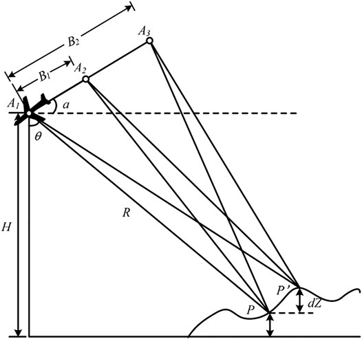
The geometry of dual-baseline InSAR is shown in Figure 1. Assuming that the antenna phase centers
Assuming that the wrapped phases corresponding to the dual-baseline InSAR are
where
If
where
In view of the similarity between solving the ambiguity number of
Adding the two equations in Eq. 3:
There are infinitely many solutions for the two equations corresponding to three unknown parameters. For the phase ambiguity number that needs to be solved, it is a set of minimum integer solutions that satisfy the equation system, which just corresponds to the fundamental solution system in the general solution of a homogeneous system of equations in linear algebra (Department of Mathematics of Tongji University. 2003). That is, the absolute value of the corresponding X is the smallest. After the phase difference
Eqs 3–5 can be transformed into the IP model as follows:
A New Branch and Bound PIP–PU Algorithm
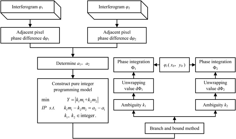
To solve the integer programming problem, it is necessary to first remove the integer constraints and convert it into a linear programming (LP) model to solve the slack problem (Eq. 7). The solution process of the branch and bound PIP–PU algorithm for dual-baseline InSAR is shown in Figure 3:
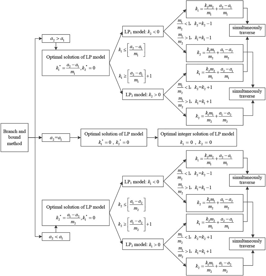
As can be seen from Figure 3, the basic idea of the branch and bound PIP–PU algorithm is as follows: using the relationship of
Ambiguity Number Solving Method
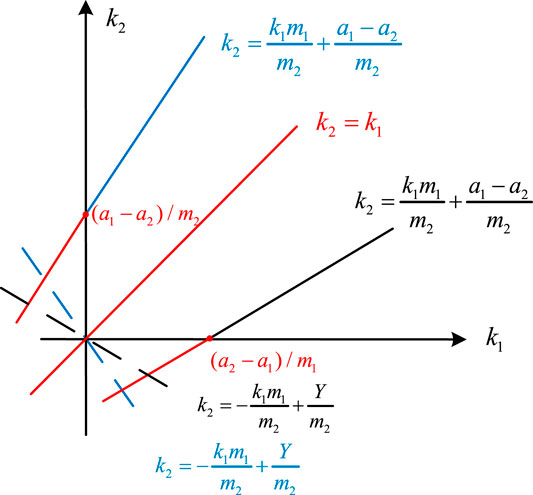
The solution of the ambiguity number can be divided into basic model and auxiliary model according to the relationship of between
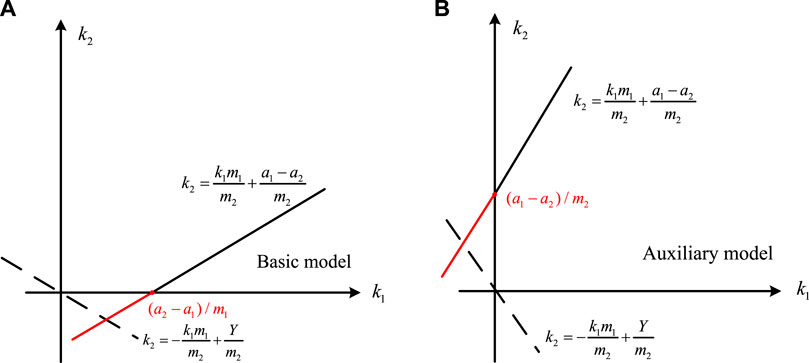
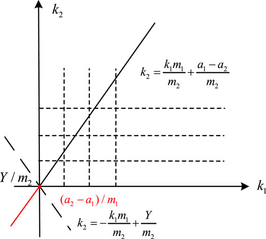
FIGURE 4. (A) Schematic diagram of objective function and constraint conditions in case of
The equation that
The optimal solution of the basic and auxiliary models can be solved, respectively:
According to the intersection of the constraint condition and the
where [] is the rounding function. As shown in Figure 4, whether it is the basic model or the auxiliary model, if only the traversal of the ambiguity number to positive direction of the coordinate axis is considered, only the
According to Eq. 5, the objective function expression can be changed:
The initial values of the ambiguity numbers
The traversal path is determined by the slope. If
In case of
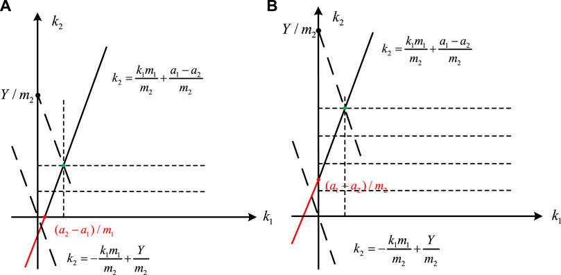
FIGURE 5. (A) Schematic diagram of
For the basic model, because of
In case of
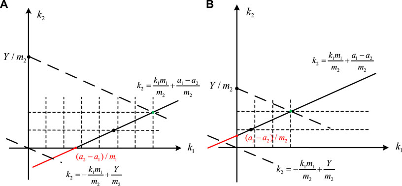
FIGURE 6. (A) Schematic diagram of
For the basic model,
So far, the positive traversal of determining the ambiguity number
Ambiguity Number Solving in a Special Case
In case of
It can be seen from the aforementioned analysis that after transforming the dual-baseline InSAR phase unwrapping problem into the PIP problem, we only need to find the corresponding algorithm to solve the integer K, and there is no requirement for the adjacent interferometric phase difference to be less than half a period. Therefore, the proposed method can extend the non-ambiguity interval to
Optimized Algorithm Using the Axis Symmetry Theory
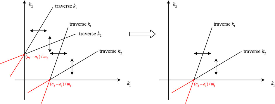
In order to further improve unwrapping efficiency, the axis symmetry theory is also introduced in this proposed method. As shown in Figure 8, if
Results and Discussion
Results and Discussion of Simulation Data
In order to verify the feasibility of the branch and bound PIP–PU algorithm for dual-baseline InSAR, the first experiment is performed on the simulated data using the sinc function. Figures 10A,B show the three-dimensional (3D) and two-dimensional (2D) digital elevation model (DEM), respectively. Figures 10C,D, respectively, show the interferograms of the short and long baselines.
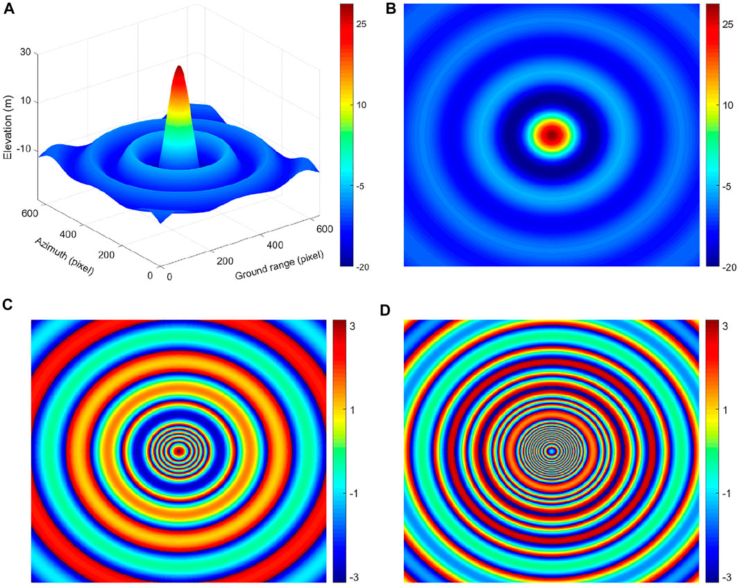
FIGURE 10. Sinc function. (A) 3D DEM (m). (B) 2D DEM (m). (C) Simulated short-baseline interferogram (rad). (D)Simulated long-baseline interferogram (rad).
After unwrapping by the branch and bound PIP–PU method, the 3D map of the solved ambiguity numbers, unwrapping results, and phase errors are shown in Figure 11. The solved ambiguity numbers are similar to the integer layer of 3D DEM. The longer the baseline, the denser the solved ambiguity numbers, and the closer the 3D map is to the 3D DEM. This is because the baseline length is proportional to the absolute phase, and the larger the absolute phase, the larger the solved ambiguity numbers. The unwrapping results show that the overall phases have good continuity; the phase errors are not only concentrated around 0, but also the order of magnitude can reach 10^–15, which prove that this proposed algorithm based on PIP mathematical ideas can effectively guarantee the accuracy of unwrapping.
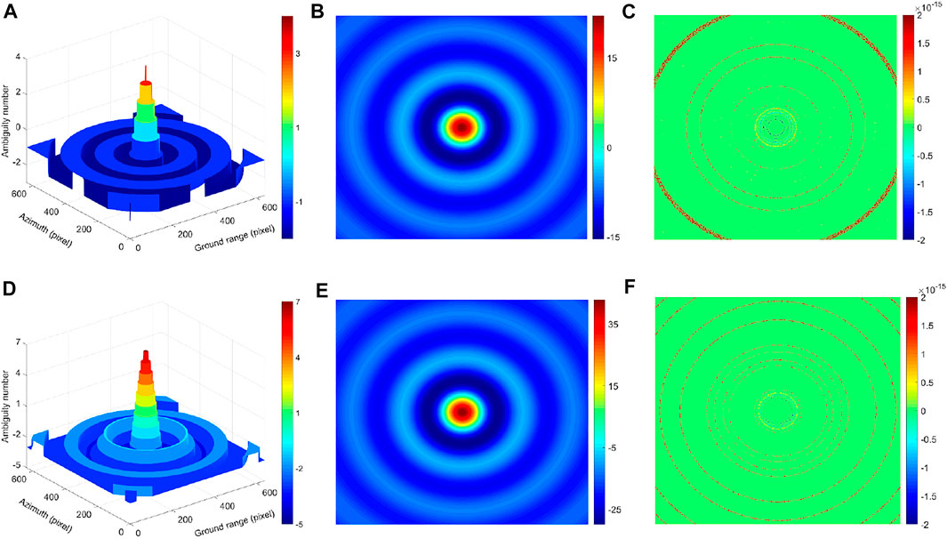
FIGURE 11. (A) 3D map of the solved ambiguity numbers for short-baseline interferogram. (B) Unwrapping results for short-baseline interferogram (rad). (C) Phase error distribution map for short-baseline interferogram (rad). (D) 3D map of the solved ambiguity numbers for long-baseline interferogram. (E) Unwrapping results for long-baseline interferogram (rad). (F) Phase error distribution map for long-baseline interferogram (rad).
Results and Discussion of Noisy Dual-Baseline Interferogram
In the second experiment, we select Isolation Peak National Park data to verify the effectiveness and noise robustness performance of this proposed method. Figures 12A,B show 2D and 3D DEM. Figures 12C,D show simulated noisy interferograms with 105 m baseline and 189 m baseline, respectively, in which we added a random phase noise with a mean value of 0 and a variance of 0.1 rad2. The main parameters are shown in Table 1.
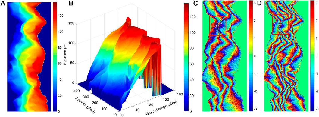
FIGURE 12. Isolation Peak National Park, United States (A) 2D DEM (m). (B) 3D DEM (m). (C) Simulated interferogram with 105 m baseline (rad). (D) Simulated interferogram with 189 m baseline (rad).
There exists phase under-sampling area in the red frame of the aforementioned interferograms. The unwrapping results of 105 m and 189 m baseline interferograms using the branch and bound PIP–PU method are shown in Figures 13A,C, respectively, which are in good agreement with Figure 12A. By further making the difference between the unwrapping result and the original reference phase, the phase error distribution map is as shown in Figures 13B,D. Better unwrapping results can be obtained even in phase under-sampling areas and abrupt topographic change areas. Compared with Figures 11C,F, although the phase error is distributed around 0, the order of magnitude becomes significantly large. It shows that this proposed algorithm is relatively sensitive to the noise. The next step should be to improve the noise robustness ability of this algorithm. But even so, the unwrapping accuracy of the proposed algorithm is still optimal, which will be proved in the following quantitative analysis.
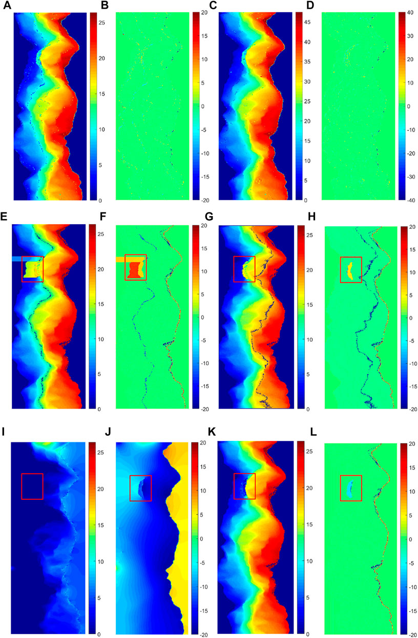
FIGURE 13. (A) Unwrapping results of the PIP method based on 105 m baseline (rad). (B) Phase error distribution map of the PIP method based on 105 m baseline (rad). (C) Unwrapping results of the PIP method based on 189 m baseline (rad). (D)Phase error distribution map of the PIP method based on 189 m baseline (rad). (E) Unwrapping results of the branch-cut method based on 105 m baseline (rad). (F) Phase error distribution map of branch-cut method based on 105 m baseline (rad). (G) Unwrapping results of the quality-guided method based on 105 m baseline (rad). (H) Phase error distribution map of the quality-guided method based on 105 m baseline (rad). (I) Unwrapping results of the LS method based on 105 m baseline (rad). (J) Phase error distribution map of the LS method based on 105 m baseline (rad). (K) Unwrapping results of the MCF method based on 105 m baseline (rad). (L) Phase error distribution map of the MCF method based on 105 m baseline (rad).
To further verify the effectiveness of the proposed method, the branch-cut method, quality-guided method, LS method, and MCF method are used to unwrap the 105 m baseline interferogram. Figures 13E,F show the unwrapping results of the branch-cut method. There exist obvious phase errors in the phase under-sampling area of the red frame, and the unwrapping effect is also poor in the abrupt topographic change area. Figures 13G,H show the unwrapping results of the quality-guided method. There is no excessive deviation, but the unwrapping effect is also poor in the phase under-sampling area and the abrupt topographic change area. Figures 13I,J show the results of the LS method. From the overall point of view, the phase continuity is guaranteed. However, the unwrapping result has too much phase deviation. Most of the data are almost 10 rad different from the original phase, and some even reach 20 rad. The main reason is that the discrete phase gradient estimation cannot reflect the true phase gradient, which introduces the large error. Figures 13K,L show the results of the MCF method. The number of error points is greatly reduced, especially in the left area. The PU effect has been greatly improved but is still not ideal in phase under-sampling areas and abrupt topographic change areas.
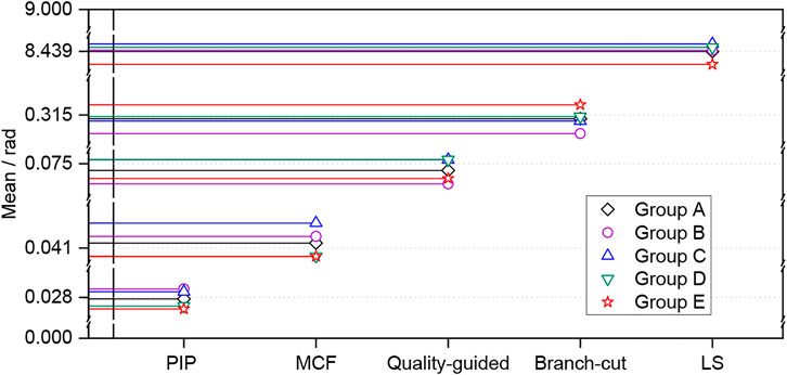
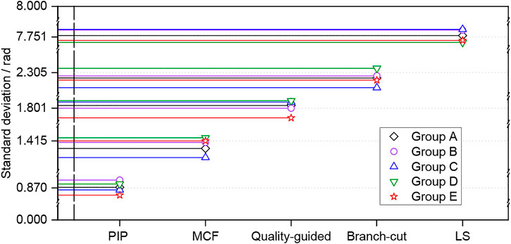
Taking into account the randomness of the noise generated by the simulation experiment, five groups of repeated experiments were performed by adding the same level of noise to the interferograms. Figures 14, 15 show the scatter plots of the mean and standard deviation of phase errors. Different algorithms focus around a different number. Both the error indicators of this proposed algorithm are always the smallest, followed by the MCF method, quality-guided method, branch-cut method, and LS method. Table 2 gives the average values of the five groups of repeated experiments. The branch-cut method has a large phase error mean and standard deviation, so the unwrapping effect is poor, but the unwrapping efficiency is higher. Compared with it, the quality-guided method has a lower mean and standard deviation, but the unwrapping efficiency is the worst. The LS method has the highest unwrapping efficiency, but the mean and standard deviation are the largest, and the unwrapping effect is also the worst. The error indicators of the MCF method are obviously smaller, and the unwrapping effect is better, but the diversity of network planning results in its low efficiency. For the PIP–PU method, the mean and standard deviation of phase errors are greatly reduced, and the unwrapping efficiency is sub-optimal. The reason is that the PIP–PU method uses rigorous mathematical expressions to accurately solve the ambiguity number, which is equivalent to realize the point-by-point unwrapping of the four neighborhoods of each reference point. Even in the phase abrupt change area, the ambiguity number can also be accurately solved, so the unwrapping accuracy is the highest. In addition, the traversal method adopts four-neighborhood expansion, which is similar to the branch-cut traversal method, so the time cost is not much different from the branch-cut method. Therefore, according to the overall performance evaluation, the unwrapping effect is relatively better, which verifies the effectiveness of the proposed method.
Results and Discussion of Real Dual-Baseline Interferogram
In the third experiment, we take the real Etna ERS-1/2 interferogram data (5,186 × 1998 pixels) to evaluate the practicality of this proposed method, which are shown in Figure 16.
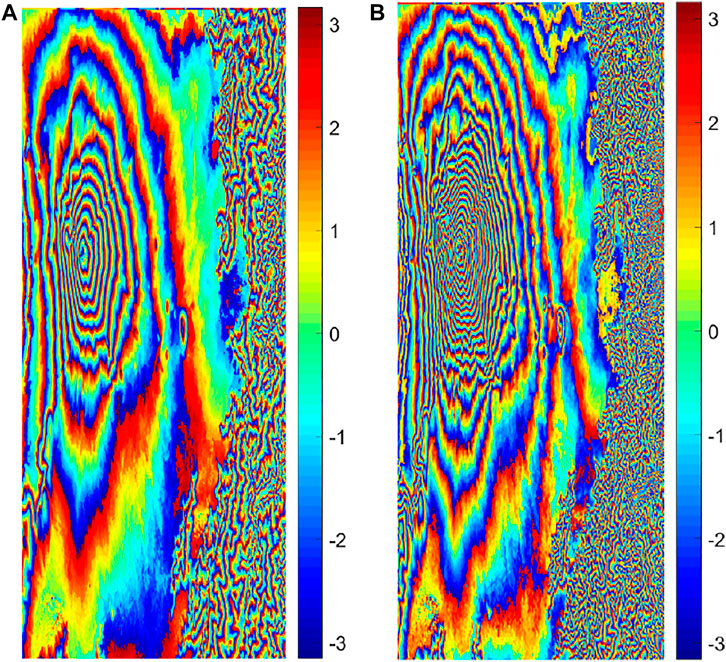
FIGURE 16. Real Etna ERS-1/2 interferograms. (A) Short-baseline interferogram (rad). (B) Long-baseline interferogram (rad).
Figures 17A,C show the 3D maps of the solved ambiguity numbers corresponding to different baseline interferograms. It can be seen that the terrain has an extreme value of the ambiguity number in the left area, so there may exist a towering terrain. Compared with the unwrapping results in Figures 17B,D, the phase distribution regularity is also consistent with that of the solved ambiguity number. Figure 17E shows the re-wrapped result of the long-baseline unwrapping phase, which is highly consistent with the original interferogram (Figure 16B), then the difference between the two can get the phase error distribution map as shown in Figure 17F, and the errors are almost 0. Finally, the inverted DEM using the long-baseline unwrapping result is shown in Figure 17G. Compared with the 3D maps of the solved ambiguity numbers (Figures 17A,C), the distribution regularity of the three are also highly consistent, which is sufficient to prove the effectiveness and practicality of the proposed algorithm.
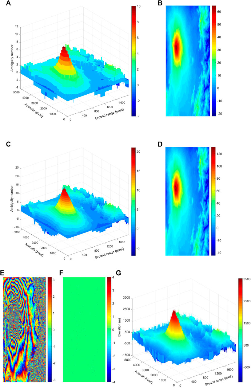
FIGURE 17. Unwrapping results of real data. (A) 3D map of the solved ambiguity numbers for short-baseline interferogram. (B) Unwrapping results for short-baseline interferogram (rad). (C) 3D map of the solved ambiguity numbers for long-baseline interferogram. (D) Unwrapping results for long-baseline interferogram (rad). (E) Re-wrapped results of long-baseline (rad). (F) Phase errors between re-wrapped results and original interferogram (rad). (G) Inverted DEM (m).
The representative algorithms were selected from the path-following type, the minimum norm type, and the optimal estimation type for this long-baseline unwrapping experiment. The unwrapping results of the branch-cut method, LS method, and MCF method are shown in Figures 18A–C, respectively. Since the integral path fails to bypass the residual point, the error propagation leads to a large number of wrong unwrapped points in the whole row of unwrapped results of the branch-cut method. The results of the LS method are similar to the unwrapping effect of the Isolation Peak National Park in the second experiment. Although the phase continuity is guaranteed, the phase errors are relatively large. The results of the MCF method are particularly good visually.
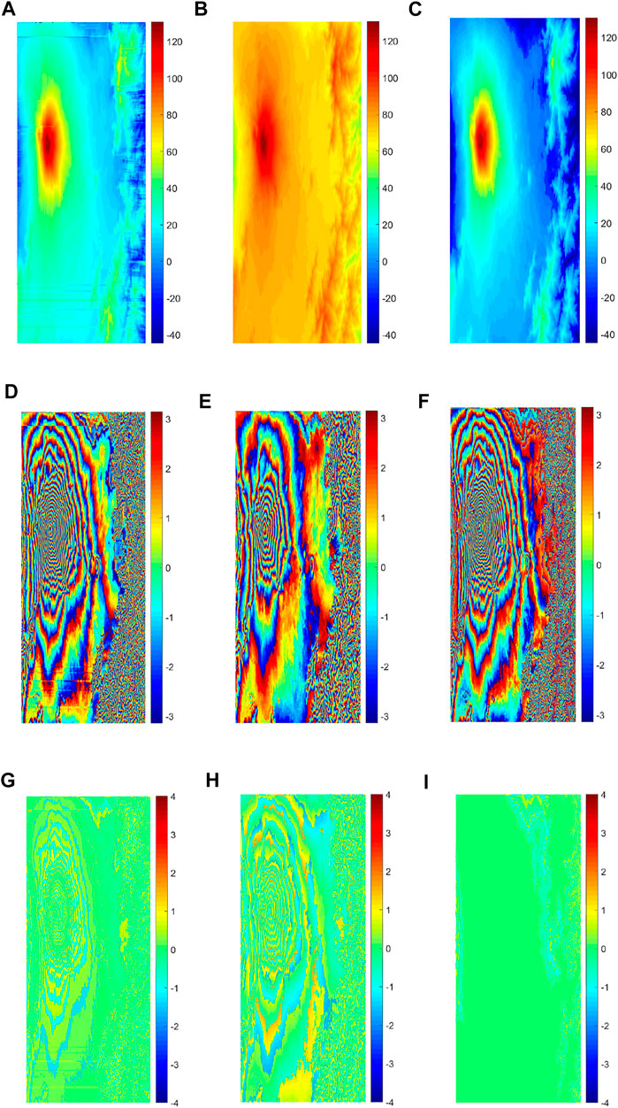
FIGURE 18. Unwrapping results of real data. (A) Branch-cut method (rad). (B) LS method (rad). (C) MFC method (rad). (D) Re-wrapped results of the branch-cut method (rad). (E) Re-wrapped results of the LS method (rad). (F) Re-wrapped results of the MFC method (rad). (G) Phase errors between re-wrapped results and original interferogram of the branch-cut method (rad). (H) Phase errors between re-wrapped results and original interferogram of the LS method (rad). (I) Phase errors between re-wrapped results and original interferogram of the MFC method (rad).
Figures 18D–F show the re-wrapped results of long-baseline unwrapping phase, and Figures 18G–I show the phase error between re-wrapped results and original interferogram. Comparing Figures 17E,F, the re-wrapped results of the branch-cut method still show a large number of wrong unwrapped points in the whole row, and phase errors from the original interferogram exhibit a ring-shaped distribution. The re-wrapped results of the LS method appear as sparser fringes, missing details of the original interferogram, so phase errors are so large that they also exhibit a more obvious ring-shaped distribution. The re-wrapped results and phase error of the MCF method are highly consistent with the original interferogram (Figure 16B), and there are some differences only in the right area. Therefore, from the visual effect of unwrapping results for real data, the proposed algorithm in this article also has the highest accuracy.
Conclusion
According to the similarity between PIP problem and solving the number of integral cycles in PU, the former is applied to the PU for dual-baseline InSAR. Taking the intercept on the vertical axis as the objective function and a ray as the constraint condition, the PIP–PU model is constructed, and a new branch and bound PIP–PU algorithm is deduced and described in detail by graphical means. This algorithm not only expands the non-ambiguity interval but also weakens the requirement of the baseline. As long as the two baselines have different lengths, the PU can be effectively solved. Finally, the two sets of simulated data by the sinc function and Isolation Peak National Park DEM and one set of real data from Etna volcano are used to conduct PU experiments. Compared with the branch-cut method, quality-guided method, LS method, and MCF method, this proposed method has more advantages in phase under-sampling areas and abrupt topographic change areas. Both visual effects and quantitative results prove the feasibility, effectiveness, and practicability of the PIP–PU algorithm. In the follow-up research, it is necessary to further verify the noise robustness ability of the PIP–PU algorithm.
Data Availability Statement
The original contributions presented in the study are included in the article/Supplementary Materials, Further inquiries can be directed to the corresponding authors.
Author Contributions
HL designed the research, proposed the method, and developed the main idea. JY contributed to experiment and analysis. QH supervised the work. GL contributed to modifying the structure of the manuscript and proofreading the manuscript. ML contributed to correcting the language and helped in layout of the manuscript. All authors have read and agreed to the published version of the final manuscript.
Funding
This work was supported by the National Natural Science Foundation of China (No. 41901411), Henan Provincial Science and Technology Research Project (No. 212102310052), Henan Youth Talent Support Program (No. 2020HYTP010), Training Plan for Young Backbone Teachers of Colleges and Universities in Henan Province (No. 2021GGJS073), Key Scientific Research Project of Colleges and Universities in Henan province (No. 19A420008), and Joint Fund of Collaborative Innovation Center of Geo-Information Technology for Smart Central Plains, Henan Province and Key Laboratory of Spatiotemporal Perception and Intelligent Processing, Ministry of Natural Resources (No. 211103).
Conflict of Interest
The authors declare that the research was conducted in the absence of any commercial or financial relationships that could be construed as a potential conflict of interest.
Publisher’s Note
All claims expressed in this article are solely those of the authors and do not necessarily represent those of their affiliated organizations, or those of the publisher, the editors, and the reviewers. Any product that may be evaluated in this article, or claim that may be made by its manufacturer, is not guaranteed or endorsed by the publisher.
Acknowledgments
The authors would like to gratefully acknowledge GuoWang Jin for his SAR technical support. The authors also thank the anonymous reviewers for their constructive comments and suggestions.
References
Bouras, I., Figueiredo, R., Poss, M., and Zhou, F. (2020). Minimizing Energy and Link Utilization in ISP Backbone Networks with Multi-Path Routing: A Bi-level Approach. Optim. Lett. 14, 209–227. doi:10.1007/s11590-019-01505-x
Chen, Q., Yang, Y. H., Liu, G. X., Cheng, H. Q., and Liu, W. T. (2012). InSAR Phase Unwrapping Using Least Squares Method with Integer Ambiguity Resolution and Edge Detection. Acta Geod. Cartogr. Sinica 41, 441–448.
Costalltilli, M. (1998). A Novel Phase Unwrapping Method Based on Network Programming. IEEE Transaction Geoscience Remote Sens. 36, 813–821. doi:10.1109/36.673674
Department of Mathematics of Tongji University (2003). Engineering Mathematics, Linear Algebra. 6th Edition. Beijing: Higher Education Press.
Dong, Y., Jiang, H., Zhang, L., and Liao, M. (2018). An Efficient Maximum Likelihood Estimation Approach of Multi-Baseline SAR Interferometry for Refined Topographic Mapping in Mountainous Areas. Remote Sens. 10, 454–474. doi:10.3390/rs10030454
Flynn, T. J. (1997). Two-dimensional Phase Unwrapping with Minimum Weighted Discontinuity. J. Opt. Soc. Am. A 14, 2692–2701. doi:10.1364/josaa.14.002692
Gao, Y., Zhang, S., Li, T., Chen, Q., Zhang, X., and Li, S. (2019). Refined Two-Stage Programming Approach of Phase Unwrapping for Multi-Baseline SAR Interferograms Using the Unscented Kalman Filter. Remote Sens. 11, 199–217. doi:10.3390/rs11020199
Ge, S. Q., Chen, L., Ding, Z. G., and Long, T. (2013). A Robust Multifrequency Phase Unwrapping Method Based on Gradient Reconstruction. Acta Geod. Cartogr. Sinica 42, 367–373+396.
Goldstein, R. M., Zebker, H. A., and Werner, C. L. (1988). Satellite Radar Interferometry: Two-Dimensional Phase Unwrapping. Radio Sci. 23, 713–720. doi:10.1029/rs023i004p00713
Jiang, Z. B., Wang, J., Song, Q., and Zhou, Z. M. (2019). A Searched-form Robust Chinese Remainder Theorem Based Multi-Baseline Phase Unwrapping Algorithm. J. Natl. Univ. Def. Technol. 41, 72–79. doi:10.11887/j.cn.201901011
Jiang, Z., Wang, J., Song, Q., and Zhou, Z. (2017). A Refined Cluster-Analysis-Based Multibaseline Phase-Unwrapping Algorithm. IEEE Geosci. Remote Sens. Lett. 14 (9), 1565–1569. doi:10.1109/lgrs.2017.2723050
Jin, B., Guo, J., Wei, P., Su, B., and He, D. (2018). Multi‐baseline InSAR Phase Unwrapping Method Based on Mixed‐integer Optimisation Model. IET Radar, Sonar & Navig. 12, 694–701. doi:10.1049/iet-rsn.2017.054310.1049/iet-rsn.2017.0543
Jin, G. W., Xu, Q., and Zhang, H. M. (2014). Synthetic Aperture Radar Interferometry. Beijing, China: National Defense Industry Press.
Jin, G. W., Zhang, H. M., Xu, Q., Qin, Z. Y., and Shi, Q. J. (2012). Phase Unwrapping Algorithm with Difference Filter for Multi-Band InSAR. Acta Geod. Cartogr. Sinica 41, 434–440+448. doi:10.3788/gzxb20124109.1130
Levitin, E., and Tichatschke, R. (1998). A Branch-And-Bound Approach for Solving a Class of Generalized Semi-infinite Programming Problems. J. Glob. Optim. 13, 299–315. doi:10.1023/A:1008245113420
Liao, M. S., and Lin, H. (2003). Synthetic Aperture Radar Interferometry-Principle and Signal Processing. Beijing, China: The Publishing House of Surveying and Mapping, 1–14.
Liu, G. L., Hao, H. D., Yan, M., and Tao, Q. X. (2011). Phase Unwrapping Algorithm by Using Kalman Filter Based on Topographic Factors. Acta Geod. Cartogr. Sinica 40, 283–288. doi:10.1109/OCEANSSYD.2010.5603794
Liu H, H., Xing, M., and Bao, Z. (2015). A Novel Mixed-Norm Multibaseline Phase-Unwrapping Algorithm Based on Linear Programming. IEEE Geosci. Remote Sens. Lett. 12, 1086–1090. doi:10.1109/lgrs.2014.2381666
Liu H T, H. T., Mengdao Xing, M. D., and Zheng Bao, Z. (2015). A Cluster-Analysis-Based Noise-Robust Phase-Unwrapping Algorithm for Multibaseline Interferograms. IEEE Trans. Geosci. Remote Sens. 53 (1), 494–504. doi:10.1109/tgrs.2014.2324595
Liu, H., Bai, Z. C., Li, G. S., Tian, D. Y., and Wang, B. C. (2019). Radar Interferometry-DEM Aided Interference and Deformation Monitoring Technology. Beijing, China: Geological Publishing House, 54–70.
Liu, H., Jin, G. W., Zhang, H. M., and Xu, Q. (2017). Phase Unwrapping Assisted by DEM of InSAR for Mountainous Terrain. J. Geomatics Sci. Technol. 34, 215–220. doi:10.3969/j.issn.1673-6338.2017.02.019
Liu, H. T. (2015). Study on Multi-Baseline Phase Unwrapping Algorithm. Xi’an: Xidian University, 19–29.
Liu, H., and Xu, Q. (2018). Interference Processing for Zero Intermediate Frequency Multi-Baseline InSAR Assisted by DEM. J. Henan Normal Univ. Nat. Sci. Ed. 46, 42–47. doi:10.16366/j.cnki.1000-2367.2018.05.007
Long, J. P., Ding, X. L., Li, Z. W., Xiang, R., and Feng, G. C. (2008). LAMBDA Method Applied to Phase Unwrapping in CR-InSAR. J. Geodesy Geodyn. 3, 100–103. doi:10.14075/j.jgg.2008.03.007
Ma, L. T., Lu, X. P., and Zhou, Y. S. (2020). An Improved Multi-Baseline InSAR Unwrapping Algorithm Based on Maximum Likelihood Estimation[J]. Sci. Surv. Mapp. 45, 123–129. doi:10.16251/j.cnki.1009-2307.2020.08.019
Markus, E. (2016). Accelerating Phase Unwrapping Based on Integer Linear Programming by Processing of Subgraphs. IEEE Transaction Geosicience Remote Sens., 6441–6444. doi:10.1109/IGARS.2016.7730683
Omer, O., Murat, E., and Ilker, B. (2020). Reliable Communication Network Design: The Hybridisation of Metaheuristics with the Branch and Bound Method. J. Operational Res. Soc. 71, 784–799. doi:10.1080/01605682.2019.1582587
Si, Q., Wang, Y., Deng, Y. K., Li, N., and Zhang, H. (2017). A Novel Cluster-Analysis Algorithm Based on MAP Framework for Multi-Baseline InSAR Height Reconstruction. J. Radars 6, 640–652. doi:10.12000/JR17043
Takajo, H., and Takahashi, T. (1988). Noniterative Method for Obtaining the Exact Solution for the Normal Equation in Least-Squares Phase Estimation from the Phase Difference. J. Opt. Soc. Am. A 5, 1818–1827. doi:10.1364/josaa.5.001818
Tang, X. M., Li, T., Gao, X. M., Chen, Q. F., and Zhang, X. (2018). Research on Key Technologies of Precise InSAR Surveying and Mapping Application Using Automatic SAR Imaging. Acta Geod. Cartogr. Sinica 47, 730–740. doi:10.11947/j.AGCS.2018.20170621
Wang, C., Zhang, H., and Liu, Z. (2002). Spaceborne Synthetic Aperture Radar Interferometry. Beijing, China: Science Press, 2–24.
Wei, X., Chang, E. C., Kwoh, L. K., Lim, H. H., and Wang, C. A. (1994). Phase-unwrapping of SAR Interferogram with Multi-Frequency or Multi-Baseline. IEEE Int. Geoscience Remote Sens. Symposium 2, 730–732. doi:10.1109/IGARSS.1994.399243
Xie, X. M., Sun, Y. Z., Liang, X. X., Zeng, Q. N., and Zheng, Z. H. (2020). Recursive Estimation Method of Cubature Kalman Filtering Local Polynomial Coefficients for Phase Unwrapping. Acta Geod. Cartogr. Sinica 49, 1023–1031. doi:10.11947/j.AGCS.2020.20190385
Yu, H., Lan, Y., Yuan, Z., Xu, J., and Lee, H. (2019). Phase Unwrapping in InSAR : A Review. IEEE Geosci. Remote Sens. Mag. 7, 40–58. doi:10.1109/mgrs.2018.2873644
Yu, H., Li, Z., and Bao, Z. (2011). A Cluster-Analysis-Based Efficient Multibaseline Phase-Unwrapping Algorithm. IEEE Trans. Geosci. Remote Sens. 49 (1), 478–487. doi:10.1109/tgrs.2010.2055569
Yu, H. W., and Bao, Z. (2013). L1-norm Method for Multi-Baseline InSAR Phase Unwrapping. J. Xidian Univ. 40 (04), 37–41. doi:10.3969/j.issn.1001-2400.2013.04.006
Yu, H. W., Cao, N., Lan, Y., and Xing, M. D. (2020). Multisystem Interferometric Data Fusion Framework: A Three-step Sensing Approach. IEEE Trans. Geoscience Remote Sens. 59, 8501–8509. doi:10.1109/TGRS.2020.3045093
Yu, H. W., and Hu, X. (2021). Knowledge-Aided InSAR Phase Unwrapping Approach. IEEE Trans. Geoscience Remote Sens. 5, 1–8. doi:10.1109/TGRS.2021.3081039
Yu, H. W., and Lan, Y. (2016). Robust Two-Dimensional Phase Unwrapping for Multibaseline SAR Interferograms: A Two-Stage Programming Approach. IEEE Trans. Geoscience Remote Sens. 54, 5217–5225. doi:10.1109/TGRS.2016.2558541
Zhang, H. M., Jin, G. W., Xu, Q., and Qin, Z. Y. (2011a). Phase Unwrapping Algorithm with Difference Filtering for Multi-Baseline InSAR. Geomatics Inf. Sci. Wuhan Univ. 36, 1030–1034. doi:10.1007/s12583-011-0162-0
Zhang, H. M., Jin, G. W., Xu, Q., Qin, Z. Y., and Sun, W. (2011b). Application of Chinese Remainder Theorem in Phase Unwrapping for Dual-Baseline InSAR. Acta Geod. Cartogr. Sinica 40, 770–777. doi:10.1631/jzus.B1000265
Zhong, H.-p., Tang, J.-s., and Zhang, S. (2011). A Combined Phase Unwrapping Algorithm Based on Quality-Guided and Minimum Discontinuity for InSAR. J. Electron. Inf. Technol. 33, 369–374. doi:10.3724/sp.j.1146.2010.00440
Keywords: interferometric synthetic aperture radar, pure integer programming, phase unwrapping, dual-baseline, slack problem, branch and bound method
Citation: Liu H, Yue J, Huang Q, Li G and Liu M (2022) A Novel Branch and Bound Pure Integer Programming Phase Unwrapping Algorithm for Dual-Baseline InSAR. Front. Environ. Sci. 10:890343. doi: 10.3389/fenvs.2022.890343
Received: 05 March 2022; Accepted: 22 April 2022;
Published: 08 June 2022.
Edited by:
Lei Zhang, Tongji University, ChinaReviewed by:
Yandong Gao, China University of Mining and Technology, ChinaHanwen Yu, University of Electronic Science and Technology of China, China
Copyright © 2022 Liu, Yue, Huang, Li and Liu. This is an open-access article distributed under the terms of the Creative Commons Attribution License (CC BY). The use, distribution or reproduction in other forums is permitted, provided the original author(s) and the copyright owner(s) are credited and that the original publication in this journal is cited, in accordance with accepted academic practice. No use, distribution or reproduction is permitted which does not comply with these terms.
*Correspondence: Hui Liu, bGg4NjA4MDFAMTYzLmNvbQ==; QiHuan Huang, SW5TQVJAaGh1LmVkdS5jbg==
 Hui Liu
 JiaWei Yue
 QiHuan Huang4*