 Jianfei Liu1
 Huihui Wang1Yongfeng Zhao2Yi Zhang3Hongbing Zhao1Weilong Zhao1Yongsheng Zhang1*Xiaowei Wang1,4,5*Xue Li6Ming Zhang7
- 1School of Civil Engineer, Henan Polytechnic University, Jiaozuo, China
- 2Henan Institute of Building Science Co., Ltd., Zhengzhou, China
- 3Henan Oilfield Engineering Consulting Co., Ltd., Zhengzhou, China
- 4School of Ecology and Environment, Beijing Technology and Business University, Beijing, China
- 5State Environmental Protection Key Laboratory of Food Chain Pollution Control, Beijing Technology and Business University, Beijing, China
- 6Solid Waste and Chemicals Technical Management Centre of Henan Province, Zhengzhou, China
- 7China Railway Zhengzhou Group Co., Ltd., Zhengzhou, China
A swirl–cyclonic flotation (SCF) apparatus was fabricated by combining hydrocyclone and air flotation separation to reduce the oil droplet load of oilfield-produced water. The apparatus was designed as three concentric cylinders with functions of swirling, air flotation separation, and oil collection. Influencing factors such as influent flow, oil concentration, and aeration rate were investigated in the pilot-scale test. The oil concentration of the effluent was below 100 mg/L during the continuous operation under an influent flow rate of 1.5 m3/h and an aeration rate of 0.4 L/min without addition of any chemicals. Results could be explained by the improvement in the floating velocity of oil droplets, resulting in oil load reduction. The oil and water separation mechanism of the SCF apparatus was determined by analysis of oil droplet size distribution. Compared with other flotation apparatus, the SCF apparatus had the advantages of high oil removal efficiency, low retention time, and stable water treatment quality. The apparatus also had no chemical agents added and had less floor area, leading to reduced chemical cost. The designed SCF apparatus has potential industrial application as pretreatment for oil–water load reduction.
Introduction
Oil is one of the most important energy sources worldwide and plays a key role in economic development. With the continuous development of oil field exploitation activities, the water content in the liquid produced is constantly rising (Liu, et al., 2021). Moreover, polymer flooding technology has become important in oil fields to improve oil recovery. Compared with traditional flooded water, oilfield-produced water contains higher amounts of organic matter, such as phenols, benzene, petroleum hydrocarbons, and polycyclic aromatic hydrocarbons, which are harmful to humans and the environment (Li, et al., 2021). In addition, treated water is not allowed to be reinjected into ground because of its excessive oil, suspended solid, and complex compound contents. Thus, oilfield-produced water is a major environmental challenge and the current research focus.
Several technologies based on different principles have been used for the treatment of oilfield-produced water. These technologies include coagulation, flocculation, centrifugation, flotation, adsorption, gravity settling, micro-filtration, reverse osmosis, biological method, activated sludge, and electrolytic methods (Yu, et al., 2017; Alammar, et al., 2020; Al-Kaabi, et al., 2021). Flotation is used to separate particulate matter from water or any other liquid (Radzuan, et al., 2016). This method is environmentally friendly because of its high efficiency, easy operation, durability, and lack of moving parts (Kargupta, et al., 2021). However, it needs large-volume equipment and addition of chemicals for emulsion breaking and should be combined with other processes (Feris, et al., 2001). The combination of air flotation and low-intensity cyclonic force is based on the new understanding of the processes of collision, coalescence, fragmentation, adhesion, and migration of microbubbles and oil droplets in a turbulent flow field. The collision adhesion probability of bubbles and oil droplets in the separation area is greatly improved by maximizing the synergistic effect of air floatation separation and low-intensity cyclonic force separation (Wang, et al., 2018). The formation of the body combined with bubbles and oil droplets is thus promoted (Saththasivam, et al., 2016). This method significantly accelerates the separation process compared with traditional air floatation. Equipment for oilfield-produced water treatment has gradually changed from a single type to an integrated apparatus that includes air flotation, swirling flow, and sedimentation instruments (Golestanbagh, et al., 2016). This kind of equipment is becoming popular because of its advantages of simple process, high degree of automation, adjustable working operation, and highly efficient processing.
The literature about the combination of air flotation and low-intensity cyclonic force method presents two issues: First, several studies have investigated the influence of operation condition and geometry parameters on the separation efficiency of apparatus (Prakash, et al., 2018; Feris, et al., 2001; Liu, et al., 2013), and second, some scholars studied separation efficiency by numerical simulation (Wang, et al., 2019; Behin and Bahrami, 2012; Lakghomi, et al., 2015). To our knowledge, the separation efficiency of equipment with various operation parameters in the pilot-scale test remains unclear.
This study aimed to investigate the oil load reduction of oilfield-produced water by swirl–cyclonic flotation (SCF) without using coagulants. Tests were conducted in batch and continuous modes. Factors (flow rate, oil concentration, and aeration rate) were evaluated to obtain the optimum operating conditions. Results can be used to expand flotation technology from a laboratory prototype to a full-scale unit and formulate appropriate control measures.
Materials and Methods
Apparatus Description
Different types of flotation apparatus are available. According to the number of cylinders, the preliminary separation zone in existing the flotation apparatus can be divided into three kinds: one cylinder (Figure 1A), two cylinders (Figure 1B), and three cylinders (Figure 1C). Given the different levels of density and interfacial tension of water and oil, the SCF apparatus contains three concentric cylinders that function in swirling, air flotation separation, and oil collection. The experimental apparatus is shown in Figure 1D. Figure 1C shows the schematic diagram of Figure 1D.
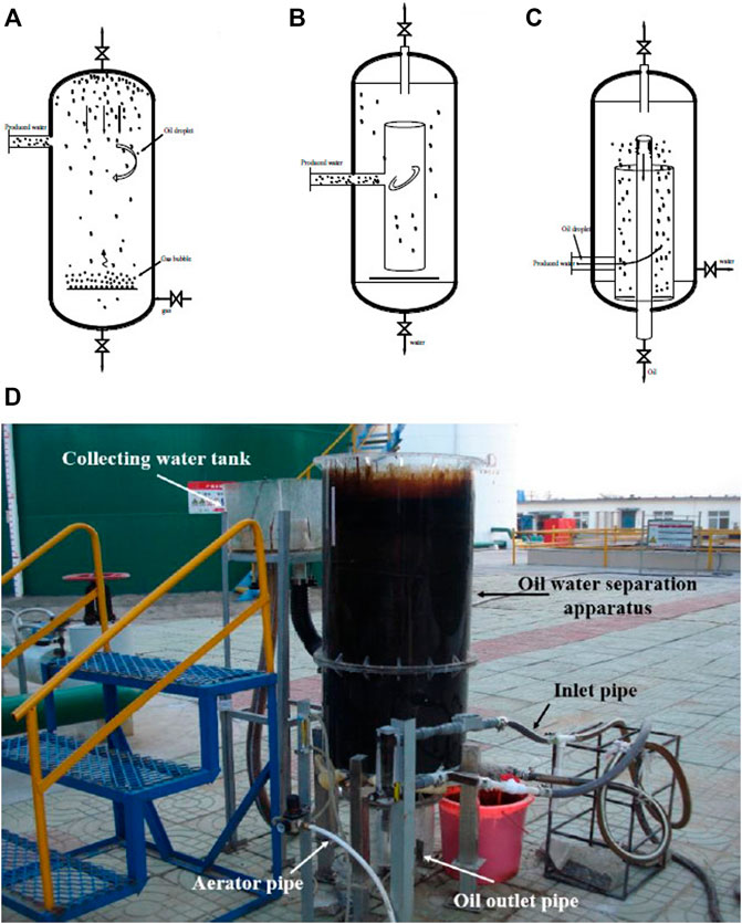
FIGURE 1. Schematic of (A) single cylinder; (B) double cylinders; (C) triple cylinders; and (D) photo of the swirl–cyclonic flotation apparatus.
The middle cylinder of 300 mm diameter was used for input of oilfield-produced water including oil and water. The inner cylinder of 75 mm diameter was used to collect oil. The outer cylinder of 500 mm diameter was used to collect wastewater. The height of the whole equipment is 1,000 mm. The center of the three cylinders is in a straight line, and the middle cylinder is sealed. The main body of the experimental apparatus was made of polymethyl methacrylate. The inlet pipe of the apparatus is located at the bottom. The exhaust valve at the top is open to atmosphere during the test to allow the entry of atmospheric pressure. The effluent from the apparatus is connected to a separate tank, which can be adjusted within a suitable height according to flow.
Materials
In the pilot test, oilfield-produced water was obtained from the effluent of the three-phase separator in Nanyang Heavy-oil Plant Co., Ltd., China. It has a total processing capacity of 13,000 m3/d, and its pretreatment process involves “two-stage sedimentation + sand filtration.” During the test, the liquid pressure was set as 0.17 MPa. The liquid temperature was 51–55°C, with an average of 52.2°C. The water content in oilfield-produced water was 95.7–97.2%, with an average of 96.4%.
Tetrachloroethylene was purchased from Tianjin Kemiou Chemical Reagent Co., Ltd., China. This chemical has a melting point of −22.2°C, a boiling point of 121.2°C, and a relative density of 1.63.
Pilot-Scale Test
Oil concentration, aeration rate, and influent flow considerably affect the oil removal efficiency. In the pilot-scale test, influent flow and aeration rate can be adjusted, while the oil concentration of oil-produced water fluctuated and cannot be adjusted.
Tests were conducted with a constant aeration rate of 0.4 L/min and a constant influent flow rate of 1.35 m3/h to investigate the effect of concentration on the removal efficiency. Influent oil concentrations were 273.24, 414.41, 563.94, 773.42, 922.19, and 1,168.1 mg/L, respectively.
Tests were conducted with a constant influent flow of 1.35 m3/h and an influent oil concentration of around 1,100 mg/L to investigate the effect of aeration rate on the removal efficiency. The aeration rates were 0.1, 0.2, 0.3, 0.4, 0.5, 0.6, and 0.7 L/min.
Influent flow rates of 0.9, 1.02, 1.35, 1.5, 1.8, and 2.1 m3/h were used with a constant aeration rate of 0.4 L/min and an influent concentration of around 1,100 mg/L to determine the effect of influent flow on the removal efficiency.
In the batch test, working condition parameters were adjusted. After it became stable, effluent was collected every 20 min. The optimum parameters of oil–water separation were determined, and continuous operation experiment was carried out.
Analysis Method
About 0.500 g of heavy oil was weighed on an analytical balance and dissolved in a 100-ml volumetric flask with petroleum ether. The oil content in the solution was 5,000 mg/L. Petroleum ether was used for stepwise dilution to 2,500, 1,000, 500, 100, 50, 10, and 5 mg/L. The oil concentrations were determined by using the JKY-3A infrared oil detector (Jilin Science and Technology Research Institute, China). The specific determination method is based on the Chinese water quality-Determination of petroleum, animal fats and vegetable oils- Infrared spectrophotometry (HJ637-2018). The reagent used in the extraction process was infrared detection reagent tetrachloroethylene. The automatic extractor was used in the extraction process strictly by the calculated residence time, ensuring that the test results more comparative. The linear regression of the test data can reflect the relationship between oil content and absorbance of oil-produced water. The standard curve is as follows:
where A is the absorbance and C is the oil content, mg/L.
A correlation coefficient of 0.9999 was obtained.
The size distribution of oil droplets was analyzed using a laser particle analyzer (BT-9300SE, Dandong Bettersize instruments Ltd., China). The drop visualization of each sample was measured by using the microscope with an objective magnification of 1,000X.
Mechanism
The floating process of oil droplets and bubbles in water is simultaneous. Therefore, the theory of the SCF work can be described by the same set of equations. The oil droplet is taken as an example for the following calculation.
The buoyancy of oil droplet in water is calculated as
where Fs is the buoyancy of oil droplet, dp is the particle size of the oil droplet, ρw is the density of the water, ρp is the density of oil droplet, and g is the acceleration of gravity, respectively.
The resistance of oil droplet in water is calculated as
where Ff is the resistance of oil droplets, λ is the resistance coefficient, and u is the floating speed of oil droplets in water, respectively.
When the rising speed of the oil droplet in the water does not change, the acceleration of the oil droplet is 0. At this time, the buoyancy of the oil droplet is the same as the resistance:
where Re is Reynolds number of oil droplet and μ is the viscosity of water.
Results and Discussion
Analysis of Factors Affecting Oil–Water Separation
The effects of oil concentration, aeration rate, and influent flow under different working conditions were investigated.
As shown in Figure 2A, removal efficiency decreased linearly with increasing influent oil concentration. Higher removal efficiency for oil was achieved at low influent oil concentrations. The frequency of collision and attachment of oil droplet and air bubbles increased at low influent oil concentrations. With increasing oil concentration, the fraction of the oil droplets that did not attach to the air bubbles increased, leading to reduction in removal efficiency (Radzuan, et al., 2016). As the oil concentration of influent oilfield-produced water increased to a certain extent, the oil film became too thick, which blocked the flow of the top oil phase. Beyond the treatment ability, of air flotation, a large oil droplet appeared near the water effluent, thereby decreasing the removal rate.
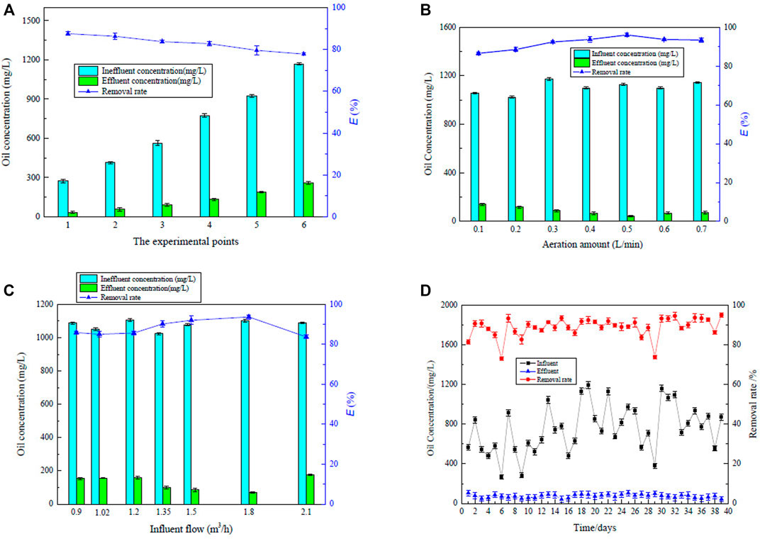
FIGURE 2. Change in the removal rate with different conditions (A) different initial oil concentrations; (B) different aeration rates; (C) different influent flows; and (D) continuous running experiment.
In the apparatus, the aeration disc has 50-μm uniform-diameter micropores. Under the action of aeration pump, bubbles were generated continuously and entered into oil-produced water. The bubble size was affected by increasing velocity, pressure, and surface tension (Leonard, et al., 2021). Some bubbles gathered to form large bubbles, and some of them burst. The bubble particle size is expected to be 10–200 μm. The oil removal rate showed a trend of increasing and then decreasing (Figure 2B). With a low aeration rate, the attachment of the oil droplets to the bubbles might not occur due to the limited number of bubbles. With increasing aeration rate, the number of bubbles increased, and the probability of collision and adhesion between the oil drops and bubbles also increased, thereby increasing the removal efficiency. Higher aeration rate and increasing velocity did not mean higher removal rate. With increasing number of bubbles, bubble–oil droplets dissociated and reduced the separation efficiency of the apparatus. This phenomenon can be explained by the existence of sheets of bubbles that can easily disturb the water flow, thereby reducing the probability of collision and adhesion between the bubbles and oil droplets. In the bubble column reactor, the main influencing parameters of the increasing velocity of bubbles are liquid superficial velocity and gas superficial velocity (Leonard, et al., 2021). Increasing the gas flow rate increased the strength of recirculation, which is expressed by the higher shear rates in the vertical liquid velocity (Panjipour, et al., 2021). Considering the energy saving and treatment effect, the ratio of aeration rate was proposed to be 0.4 L/min.
As shown in Figure 2C, with increasing influent flow from 0.9 m3/h to 1.8 m3/h, the corresponding oil removal rate increased first and then decreased. To ensure that the water flow can rotate and rise, the water flow should be maintained at a certain rate. A suitable flow is beneficial to promote the collision, coalescence, migration, and separation between bubbles and oil droplets. If the flow rate is too slow, the hydraulic separation becomes too weak to separate the oil from oilfield-produced water. If the flow rate is too high, the shear stress of the fluid increases, leading to increased breaking ratio of the adhesive body of oil droplets and bubbles. At the same time, a high influent flow results in low hydraulic retention time of oilfield-produced water in the apparatus and low chance of collision and adhesion between the bubbles and oil droplets. In addition, high influent flow means that the high influent rate needs more energy.
A continuous stability experiment was carried out under a influent flow rate of 1.5 m3/h and aeration rate of 0.4 L/min for 39 days to verify the separation performance and operational stability of the SCF apparatus during operation. The oil concentration was measured 12 times every day, and the average value was taken as the test value. The oil removal rate curve is shown in Figure 2D. When the oil influent concentration of the oilfield-produced water fluctuated within 200–1,200 mg/L during continuous operation, the oil removal rate was 73.09–94.94%, with an average of 92.43%. The minimum effluent concentration appeared at 15th day with the concentration of 41.61 mg/L. In oilfield-produced water with fluctuating concentration, the effluent concentration was stable, indicating that the SCF apparatus presented good adaptability. Compared with the current process in the plant, the removal effect presented no less than the two-stage sedimentation with less floor area. Hence, the apparatus had high separation efficiency and good operational stability in line with the expected operating indicators.
The effluent oil content exceeded the reinjection standard of China. Considering that low concentration water is conducive to oil–water separation, part of the discharged water can be reinjected to the influent oilfield-produced water to reduce the concentration of the influent water when the concentration is high. Two SCF apparatus can be connected in series to reduce the effluent concentration in actual engineering. In the plant, the discharge water enters the sand filter tank and is finally used for boiler water or groundwater reinjection. SCF has potential industrial application as a pretreatment process for oil–water load reduction.
Oil Separation Mechanism
The oil field-produced water enters tangentially into the middle cylinder and enhances the collision adhesion between the oil droplets and air bubbles, thereby improving the flotation efficiency. When the oil field-produced water enters the SCF apparatus, the separation of the oil phase and water phase occurs. Under the action of SCF, the heavier phase moves to the wall of the cylinder, and the lighter phase moves to the central position. Oil–water separation is a complex process that involves the surface characteristics of oil droplets and their interaction with bubbles (Moosai and Dawe, 2003). Three-phase separation occurs at the liquid/air interface in the SCF apparatus. In the early stage of operation, no film was formed, and the oil concentration in the effluent was high. With the continuous generation, the bubble–oil droplet adhering body floated together and continued to increase at the liquid/air interface. When the experimental conditions are stable, an equilibrium relationship exists between bubble–oil droplet and bubble in the oil–liquid film. The oil droplets are separated from oil-produced water in the oil–liquid film. Three different types of behavior occur in the films when it comes to a stable operation condition. Oil droplets will be skimmed off from the film and flow into the inner cylinder. The heavier water will move to the outside cylinder under cyclonic force, and bubbles will release into the atmosphere. Compared with pure air flotation, the bubble–oil droplet adhering body will rise faster under the action of swirling flow, indicating that the oil–water separation time can be shortened (Edzwald, 2010). Based on Formula 6, the rising velocity of oil droplets can be calculated and shown in Figure 3A. With the oil droplet with 120 µm diameter as example, the floating speed is 9.9 mm/s, and its hydraulic retention time is only about 98 s. Thus, the compact design, low retention time, and high removal rate are the advantages of the SCF apparatus.
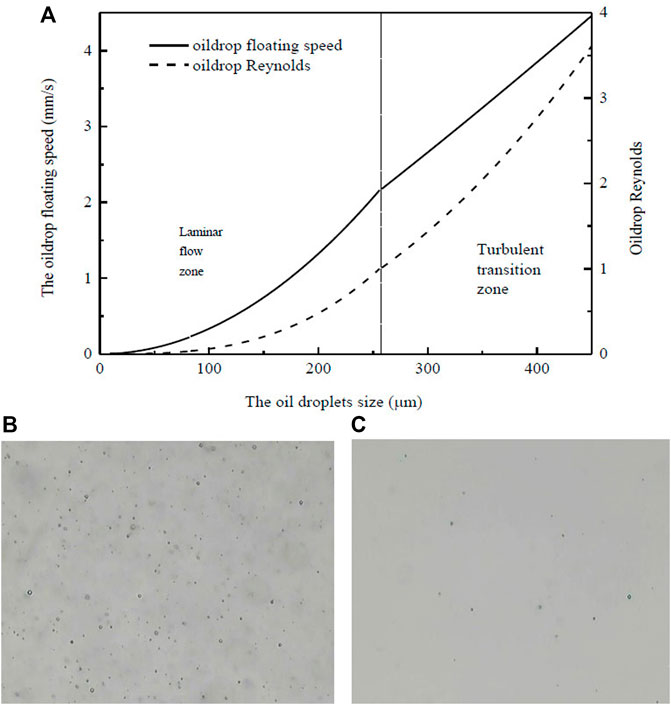
FIGURE 3. Floating speed (A) and distribution of oil droplets in influent (B) and effluent (C) of oilfield-produced water.
The rising velocity of oil droplets gradually increases with increasing oil droplet size. The Reynolds number is a basic parameter used to estimate flow pattern (Xu, et al., 2018). When the oil droplets have particle sizes of 100, 200, and 300 μm, the rising velocities are 0.33, 1.32, and 2.65 mm/s, and the Reynolds numbers are 0.06, 0.47, and 1.43, respectively. All the Reynolds number of oil droplet is below 4.5, which indicate that oil droplets are in the laminar flow area and transition area. The free-floating bubbles has little disturbance to the fluid, and the oil droplets flow under the low-intensity cyclonic force.
The oil droplet distribution in the oilfield-produced water was obtained using a BT-9300SE laser particle size analyzer to clarify the oil and water separation mechanism. When the influent oil concentration was 1,193.26 mg/L, the particle size of the oil droplets in D50 was 250.6 µm, and the maximum particle size of the oil droplets was 900.9 µm. When the effluent oil concentration was 90.32 mg/L, the particle size of D50 oil drops was 13.7 µm and the maximum particle size was 219.3 µm, indicating that part of the emulsified oil with larger particle size was removed by floatation. The removal rates of free oil, dispersed oil, and emulsified oil were 99.98, 80.48, and 61.52%, respectively. Hence, the SCF apparatus is the most effective in removing free oil, and the main form of oilfield-produced water is free oil.
The state of the oil droplets was observed under a Belona biological microscope. As shown in Figure 3B, the number of oil droplets is dense and the oil concentration is relatively high. The oil droplets are “ball”-shaped caused by the interface tension between oil and water. Figure 3C shows the existing state of oil droplets in the effluent after air flotation. The number of oil droplets in the effluent is sparse, and the particle size of oil droplets is very small, indicating that air flotation has a good treatment effect on the emulsified oil.
Analysis of Advantages Over Other Flotation Apparatus
The characteristic of the single cylinder is that oil droplets attached to the bubbles move upward with the bubbles, while water moves downward under gravity to the bottom of the apparatus. The main characteristic of the double cylinders is that oil-produced water enters the inner cylinder, which is often installed at the top of the apparatus. Oil droplets attached with the bubbles rise to the oil-phase concentration zone, while the water flows along the wall of the inner cylinder and flows down to the bottom of the vessel. The remarkable characteristic of the three cylinders is that oilfield-produced water enters the middle cylinder. The oil phase can flow into the inner cylinder, and the water phase can flow into the outside cylinder continuously under cyclonic force. Table 1 summarizes the characteristics of flotation apparatus in the literature. The compact design of the developed apparatus in the present work has three concentric cylinders that function in swirling, air flotation separation, and oil collection.
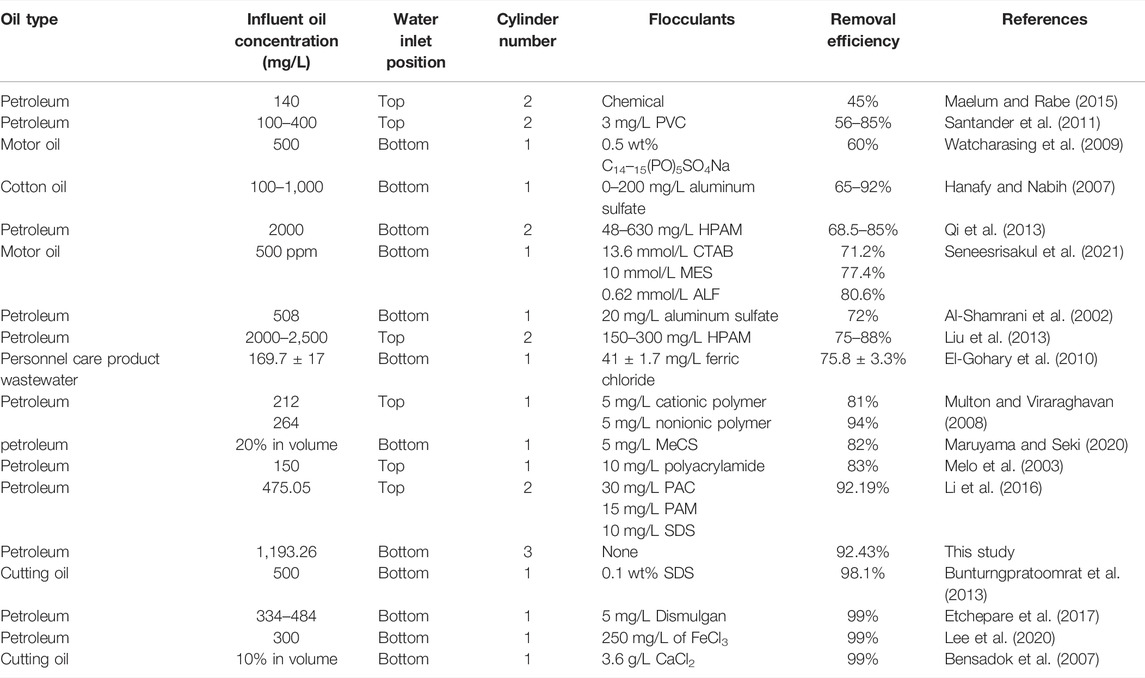
TABLE 1. Characteristics of flotation apparatus.
The removal efficiency can be greatly improved by adding coagulants because coagulated droplets can easily absorb or entrap air bubbles. The oil removal rate can be greatly improved with chemicals (Wang, et al., 2010; El-Gohary, et al., 2010). However, coagulant aid and flocculant in the separation process could produce a large amount of scum, which is not conducive to the recovery and utilization of waste oil. The scum produces mechanical wear and corrosion and causes secondary pollution. The removal rate of the SCF apparatus is higher than that of apparatus in the literature, which can be attributed to the unique compact design of the apparatus. High separation efficiency can be achieved without adding any chemical agents by the apparatus in this work, which also means many chemicals cost could be saved. Therefore, the designed SCF apparatus is suitable for the oil–water load reduction as a pretreatment process.
Conclusion
An oil–water separation apparatus with three cylinders was developed by combining hydrocyclone and air flotation separation principle to determine the separation effectiveness of oil and water from oilfield-produced water. Batch and continuous modes were conducted in the pilot test. The optimum operating conditions consisted of an influent flow rate of 1.5 m3/h and an aeration rate of 0.4 L/min by batch test.
In the continuous running mode, the oil removal rate generally was above 90% with fluctuating concentration under the optimum operating conditions. Compared with other flotation apparatus, the SCF apparatus exhibits the advantages of compact design, lower retention time, and higher removal rate. Two SCF apparatus can be connected in series to reduce the effluent concentration in the actual engineering.
The popularization and application of the designed SCF pretreatment equipment can reduce the oil–water load without using chemicals. As such, the harmful solid oil sludge can be greatly reduced to achieve an environment-friendly and cost-saving operation.
Data Availability Statement
The original contributions presented in the study are included in the article/Supplementary Material, further inquiries can be directed to the corresponding authors.
Author Contributions
JL: data curation, methodology, writing—original draft; HW: methodology and data curation; YoZ: methodology and data curation; YiZ: methodology and project administration; HZ: methodology; WZ: data curation and investigation; YSZ: methodology and writing—original draft; XW: methodology and writing—original draft; and XL: project administration and resources.
Funding
This study received funding from Key scientific research projects of universities of Henan Provincial Department of Education, China (21B610006), the Fundamental Research Funds for the Universities of Henan Province, China (NSFRF210457), and Henan oilfield Engineering Consulting Co., Ltd. The funder had the following involvement with the study of oils load reduction of oilfield-produced water application of swirl–cyclonic flotation. All authors declare no other competing interests.
Conflict of Interest
YoZ is employed by the Henan Institute of Building Science Co., Ltd. YiZ is employed by Henan Oilfield Engineering Consulting Co., Ltd. XL is employed by the Solid Waste and Chemicals Technical Management Centre of Henan Province. Author MZ is employed by China Railway Zhengzhou Group Co., Ltd.
The remaining authors declare that the research was conducted in the absence of any commercial or financial relationships that could be construed as a potential conflict of interest.
Publisher’s Note
All claims expressed in this article are solely those of the authors and do not necessarily represent those of their affiliated organizations, or those of the publisher, the editors, and the reviewers. Any product that may be evaluated in this article, or claim that may be made by its manufacturer, is not guaranteed or endorsed by the publisher.
Supplementary Material
The Supplementary Material for this article can be found online at: https://www.frontiersin.org/articles/10.3389/fenvs.2022.883877/full#supplementary-material
References
Al-Kaabi, M. A., Zouari, N., Da'Na, D. A., and Al-Ghouti, M. A. (2021). Adsorptive Batch and Biological Treatments of Produced Water: Recent Progresses, Challenges, and Potentials. J. Environ. Manage. 290, 112527. doi:10.1016/j.jenvman.2021.112527
Al-Shamrani, A. A., James, A., and Xiao, H. (2002). Separation of Oil from Water by Dissolved Air Flotation. Colloids Surf. A: Physicochem. Eng. Aspects 209, 15–26. doi:10.1016/S0927-7757(02)00208-X
Alammar, A., Park, S.-H., Williams, C. J., Derby, B., and Szekely, G. (2020). Oil-in-water Separation with Graphene-Based Nanocomposite Membranes for Produced Water Treatment. J. Membr. Sci. 603, 118007. doi:10.1016/j.memsci.2020.118007
Aliff Radzuan, M. R., Abia-Biteo Belope, M. A., and Thorpe, R. B. (2016). Removal of fine Oil Droplets from Oil-In-Water Mixtures by Dissolved Air Flotation. Chem. Eng. Res. Des. 115, 19–33. doi:10.1016/j.cherd.2016.09.013
Behin, J., and Bahrami, S. (2012). Modeling an Industrial Dissolved Air Flotation Tank Used for Separating Oil from Wastewater. Chem. Eng. Process. Process Intensif. 59, 1–8. doi:10.1016/j.cep.2012.05.004
Bensadok, K., Belkacem, M., and Nezzal, G. (2007). Treatment of Cutting Oil/water Emulsion by Coupling Coagulation and Dissolved Air Flotation. Desalination 206, 440–448. doi:10.1016/j.desal.2006.02.070
Bunturngpratoomrat, A., Pornsunthorntawee, O., Nitivattananon, S., Chavadej, J., and Chavadej, S. (2013). Cutting Oil Removal by Continuous Froth Flotation with Packing media under Low Interfacial Tension Conditions. Sep. Purif. Technol. 107, 118–128. doi:10.1016/j.seppur.2013.01.024
Edzwald, J. K. (2010). Dissolved Air Flotation and Me. Water Res. 44, 2077–2106. doi:10.1016/j.watres.2009.12.040
El-Gohary, F., Tawfik, A., and Mahmoud, U. (2010). Comparative Study between Chemical Coagulation/precipitation (C/P) versus Coagulation/dissolved Air Flotation (C/DAF) for Pre-treatment of Personal Care Products (PCPs) Wastewater. Desalination 252, 106–112. doi:10.1016/j.desal.2009.10.016
Etchepare, R., Oliveira, H., Azevedo, A., and Rubio, J. (2017). Separation of Emulsified Crude Oil in saline Water by Dissolved Air Flotation with Micro and Nanobubbles. Sep. Purif. Technol. 186, 326–332. doi:10.1016/j.seppur.2017.06.007
Féris, L. A., Gallina, C. W., Rodrigues, R. T., and Rubio, J. (2001). Optimizing Dissolved Air Flotation Design and Saturation. Water Sci. Technol. 43, 145–157. doi:10.2166/wst.2001.0486
Golestanbagh, M., Parvini, M., and Pendashteh, A. (2016). Integrated Systems for Oilfield Produced Water Treatment: The State of the Art. Energy Sourc. A: Recovery, Util. Environ. Effects 38, 3404–3411. doi:10.1080/15567036.2016.1154903
Hanafy, M., and Nabih, H. I. (2007). Treatment of Oily Wastewater Using Dissolved Air Flotation Technique. Energ. Sourc. Part A: Recovery, Util. Environ. Effects 29, 143–159. doi:10.1080/009083190948711
Kargupta, W., Browne, C., Verdugo, L., Hunt, I., Stack, K., Batchelor, W., et al. (2021). Flotation as a Separation Technology for Recovering Pulp Fines and Sustainable Nanocellulose Production. Sep. Purif. Technol. 270, 118810. doi:10.1016/j.seppur.2021.118810
Lakghomi, B., Lawryshyn, Y., and Hofmann, R. (2015). A Model of Particle Removal in a Dissolved Air Flotation Tank: Importance of Stratified Flow and Bubble Size. Water Res. 68, 262–272. doi:10.1016/j.watres.2014.09.053
Lee, J., Cho, W.-C., Poo, K.-M., Choi, S., Kim, T.-N., Son, E.-B., et al. (2020). Refractory Oil Wastewater Treatment by Dissolved Air Flotation, Electrochemical Advanced Oxidation Process, and Magnetic Biochar Integrated System. J. Water Process Eng. 36, 101358. doi:10.1016/j.jwpe.2020.101358
Leonard, C., Ferrasse, J.-H., Lefevre, S., Viand, A., and Boutin, O. (2021). Bubble Rising Velocity and Bubble Size Distribution in Columns at High Pressure and Temperature: From Lab Scale Experiments to Design Parameters. Chem. Eng. Res. Des. 173, 108–118. doi:10.1016/j.cherd.2021.07.003
Li, C., Li, J., Wang, N., Zhao, Q., and Wang, P. (2021). Status of the Treatment of Produced Water Containing Polymer in Oilfields: A Review. J. Environ. Chem. Eng. 9, 105303. doi:10.1016/j.jece.2021.105303
Li, X., Xu, H., Liu, J., Zhang, J., Li, J., and Gui, Z. (2016). Cyclonic State Micro-bubble Flotation Column in Oil-In-Water Emulsion Separation. Sep. Purif. Technol. 165, 101–106. doi:10.1016/j.seppur.2016.01.021
Liu, J., Xu, H., and Li, X. (2013). Cyclonic Separation Process Intensification Oil Removal Based on Microbubble Flotation. Int. J. Mining Sci. Technol. 23, 415–422. doi:10.1016/j.ijmst.2013.05.010
Liu, Y., Lu, H., Li, Y., Xu, H., Pan, Z., Dai, P., et al. (2021). A Review of Treatment Technologies for Produced Water in Offshore Oil and Gas fields. Sci. Total Environ. 775, 145485. doi:10.1016/j.scitotenv.2021.145485
Maelum, M., and Rabe, K. (2015). Improving Oil Separation from Produced Water Using New Compact Flotation Unit Design. Oklahoma City, Oklahoma, USA: SPE Publications.
Maruyama, H., and Seki, H. (2020). Influence of Methylated Milk Casein Flocculant Dosage on Removal Rate of Oil Droplet Removal from O/w in Flotation. Biochem. Eng. J. 159, 107584. doi:10.1016/j.bej.2020.107584
Melo, M. V., Sant’Anna, G. L., and Massarani, G. (2003). Flotation Techniques for Oily Water Treatment. Environ. Technol. 24, 867–876. doi:10.1080/09593330309385623
Moosai, R., and Dawe, R. A. (2003). Gas Attachment of Oil Droplets for Gas Flotation for Oily Wastewater Cleanup. Sep. Purif. Technol. 33, 303–314. doi:10.1016/S1383-5866(03)00091-1
Multon, L. M., and Viraraghavan, T. (2008). Removal of Oil from Produced Water by Dissolved Air Flotation. Pract. Periodical Hazard. Tox. Radioact. Waste Manage. 12, 25–29. doi:10.1061/(asce)1090-025x(2008)12:1(25)
Panjipour, R., Karamoozian, M., and Albijanic, B. (2021). Bubble Size Distributions in Gas-Liquid-Solid Systems and Their Influence on Flotation Separation in a Bubble Column. Chem. Eng. Res. Des. 167, 96–106. doi:10.1016/j.cherd.2021.01.001
Prakash, R., Majumder, S. K., and Singh, A. (2018). Flotation Technique: Its Mechanisms and Design Parameters. Chem. Eng. Process. - Process Intensif. 127, 249–270. doi:10.1016/j.cep.2018.03.029
Qi, W.-K., Yu, Z.-C., Liu, Y.-Y., and Li, Y.-Y. (2013). Removal of Emulsion Oil from Oilfield ASP Wastewater by Internal Circulation Flotation and Kinetic Models. Chem. Eng. Sci. 91, 122–129. doi:10.1016/j.ces.2013.01.020
Santander, M., Rodrigues, R. T., and Rubio, J. (2011). Modified Jet Flotation in Oil (Petroleum) Emulsion/water Separations. Colloids Surf. A: Physicochem. Eng. Aspects 375, 237–244. doi:10.1016/j.colsurfa.2010.12.027
Saththasivam, J., Loganathan, K., and Sarp, S. (2016). An Overview of Oil-Water Separation Using Gas Flotation Systems. Chemosphere 144, 671–680. doi:10.1016/j.chemosphere.2015.08.087
Seneesrisakul, K., Kanokkarn, P., Charoensaeng, A., and Chavadej, S. (2021). Motor Oil Removal from Water by Continuous Froth Flotation: The Influence of Surfactant Structure on Interfacial Adsorption and Foam Properties. Colloids Surf. A: Physicochem. Eng. Aspects 618, 126499. doi:10.1016/j.colsurfa.2021.126499
Wang, C., Wang, Z., Wei, X., and Li, X. (2019). A Numerical Study and Flotation Experiments of Bicyclone Column Flotation for Treating of Produced Water from ASP Flooding. J. Water Process Eng. 32, 100972. doi:10.1016/j.jwpe.2019.100972
Wang, G., Ge, L., Mitra, S., Evans, G. M., Joshi, J. B., and Chen, S. (2018). A Review of CFD Modelling Studies on the Flotation Process. Minerals Eng. 127, 153–177. doi:10.1016/j.mineng.2018.08.019
Watcharasing, S., Kongkowit, W., and Chavadej, S. (2009). Motor Oil Removal from Water by Continuous Froth Flotation Using Extended Surfactant: Effects of Air Bubble Parameters and Surfactant Concentration. Sep. Purif. Technol. 70, 179–189. doi:10.1016/j.seppur.2009.09.014
Xu, X., Ge, X. L., Qian, Y. D., Wang, H. L., and Yang, Q. (2018). Bubble‐Separation Dynamics in a Planar Cyclone: Experiments and CFD Simulations. Aiche J. 64, 2689–2701. doi:10.1002/aic.16115
Keywords: oilfield-produced water, swirl–cyclonic flotation, pilot scale, bubble floating velocity, separation
Citation: Liu J, Wang H, Zhao Y, Zhang Y, Zhao H, Zhao W, Zhang Y, Wang X, Li X and Zhang M (2022) Oil Load Reduction of Oilfield-Produced Water by Applying Swirl–Cyclonic Flotation: A Pilot-Scale Investigation. Front. Environ. Sci. 10:883877. doi: 10.3389/fenvs.2022.883877
Received: 25 February 2022; Accepted: 30 March 2022;
Published: 09 May 2022.
Edited by:
Shihai Deng, Xi’an Jiaotong University, ChinaReviewed by:
Xiao Xu, East China University of Science and Technology, ChinaHelian Li, University of Jinan, China
Copyright © 2022 Liu, Wang, Zhao, Zhang, Zhao, Zhao, Zhang, Wang, Li and Zhang. This is an open-access article distributed under the terms of the Creative Commons Attribution License (CC BY). The use, distribution or reproduction in other forums is permitted, provided the original author(s) and the copyright owner(s) are credited and that the original publication in this journal is cited, in accordance with accepted academic practice. No use, distribution or reproduction is permitted which does not comply with these terms.
*Correspondence: Yongsheng Zhang, emhvbmd5b25nc2hlbmdAaHB1LmVkdS5jbg==; Xiaowei Wang, eGlhb193ZWlfd2FuZ0AxMjYuY29t