 Andrew D. Putt1
 Miguel Rodriguez
  Terry C. Hazen
- 1Department of Earth and Planetary Sciences, University of Tennessee, Knoxville, TN, United States
- 2Biosciences Division, Oak Ridge National Laboratory, Oak Ridge, TN, United States
- 3Department of Microbiology, University of Tennessee, Knoxville, TN, United States
- 4Department of Civil and Environmental Sciences, University of Tennessee, Knoxville, TN, United States
- 5Institute for a Secure and Sustainable Environment, University of Tennessee, Knoxville, TN, United States
Penetration testing is a popular and instantaneous technique for subsurface mapping, contaminant tracking, and the determination of soil characteristics. While the small footprint and reproducibility of cone penetrometer testing makes it an ideal method for in-situ subsurface investigations at contaminated sites, the effects to local shallow groundwater wells and measurable influence on monitoring networks common at contaminated sites is unknown. Physical and geochemical parameters associated with cone penetrometer testing were measured from a transect of shallow groundwater monitoring wells adjacent to penetrometer testing. For wells screened above the depth of cone refusal, the physical advancement and retraction of the cone had a significant effect (p < 0.01) on water level for several pushes within 10 meters of a monitoring well, and a measured increase in specific conductivity. No effect on geochemistry or water level was observed in continuous monitoring data from wells screened below the depth of cone refusal, but variability in specific conductivity from these wells during penetration testing was only a fraction of the natural variation measured during precipitation events. Continuous measurements of specific conductivity and water level demonstrated that the effects of penetration testing have limited spatial and temporal distributions with a null effect post-testing.
1 Introduction
Soil core recovery and penetration testing methods are popular techniques for measuring soil compaction, behavior, stratigraphy, porosity, and permeability for a variety of geotechnical and engineering applications. While soil core recovery requires subsequent processing and compaction corrections; penetration testing provides instant continuous data in-situ with a lower relative cost, lower risk of cross contamination, and high reliability making it a widely used and highly standardized method for subsurface investigations (American Society for Testing and Materials, 2018).
Cone Penetrometer Testing (CPT) is conducted by advancing a cone penetrometer downward through soft subsurface material at a constant rate while measuring penetration resistance (American Society for Testing and Materials, 2018). Cone penetrometers measure the axial force of sediment acting on the cone divided by projected area of the cone which is recorded as cone tip resistance qc (MPa), and total force acting on the friction sleeve divided by the area of the friction sleeve recorded as sleeve friction fs (MPa). Cone penetrometers that measure pore pressure u (kPa), like the one used in this study, are called piezocones and measure soil pressure either in the cone (u1), between the cone tip and friction sleeve (u2) like in Figure 1 or above the friction sleeve (u3). Pore pressure measured between the cone tip and friction sleeve is often applied as a correction for cone tip resistance qt [qt = qc + u2(1-an)] (Robertson, 2010) with the ratio between the diameter of the load cell support (d) and the diameter of the cone (D) calculated as the net area ratio an [an = d2/D2] (Robertson, 2010). Interval data from cone penetrometers can be used to determine soil behavior type from friction ratio, Rf (%) [Rf = (fs/qt) x 100] using the corrected cone resistance qt (Schmertmann, 1978; Robertson, 1990). In addition to measuring soil behavior types, other sensors can be deployed with the cone penetrometer for subsurface measurements of contaminants. These include sensors for hydrocarbons, volatile organics, toxic metals, explosives/energetics, and radioactive wastes (Malone et al., 1992; Doskey and Cespedes, 2006). CPT methodologies are optimized for various sediment types including the variably compacted soft sediments (Schmertmann, 1978; Robertson, 1986; Campanella et al., 1990; Robertson, 1990; Doskey and Cespedes, 2006; Robertson, 2010) like the residuum and back fill found at this site (Campanella et al., 1990; Robertson, 1990; Hatcher et al., 1992; Sutton Jr and Field, 1995; Robertson, 2010; American Society for Testing and Materials, 2020), but some may be hesitant to use these techniques since the spatiotemporal effects of penetration on pre-existing monitoring networks are largely unknown.
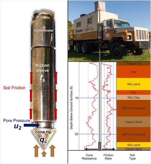
FIGURE 1. Type 2 piezocone sensors (left) measure the axial force on the cone, the upward friction, and the inward pore pressure to determine soil behavior which is interpreted during piezocone advancement (right).
Continuous monitoring and non-continuous measures were used to assess hydrologic and geochemical changes during a recent penetration study at the Oak Ridge Integrated Field Research Challenge Site within the Y-12 National Security Complex in Oak Ridge, Tennessee, TN, United States. The effects of CPT were quantified from common continuous monitoring parameters such as dissolved oxygen, specific conductivity, pH, suspended solids, salinity, and depth to water measured during penetration and borehole grouting. Responses in water level change were further compared with sediment behavior type to determine if the effect of penetration was related to differences in subsurface material measured on the piezocone.
The penetration testing occurred within a 2,600 square meter site (Figure 2A) immediately down-gradient of the S3 parking lot that overlies the former clay-lined S3 transuranic and nitric acid waste ponds (Watson et al., 2004). The site, functionally known as Area 3, has a shallow water table, relatively flat hydraulic gradient, and southerly flow (Hatcher et al., 1992; Oak Ridge Y-12 Plant, T.N, 1995; Watson et al., 2004;Revil et al., 2013). Area 3 is located in Bear Creek Valley, and consists primarily of saprolite clay and silt with a history of excavations, stream relocation, and waste burial (Hatcher et al., 1992; Oak Ridge Y-12 Plant, T.N, 1995; Watson et al., 2004). The primary pathway for shallow contaminant transport in Area 3 is fracture mediated flow in weathered saprolite and fill materials (Hatcher et al., 1992; Oak Ridge Y-12 Plant, T.N, 1995; Watson et al., 2004;Revil et al., 2013). The preferential transport pathways interact with FW103, FW024, and FW106 (Figure 2A) where high concentrations of contaminants including nitric acid, uranium, Th-230, Tc-99, sulfate, phosphate, strontium, cadmium, barium, boron, mercury, and chromium have been identified (Hatcher et al., 1992; Oak Ridge Y-12 Plant, T.N, 1995; Watson et al., 2004; Revil et al., 2013).
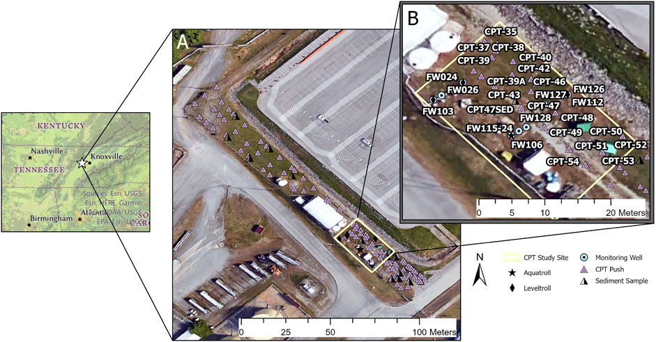
FIGURE 2. Map of cone penetrometer testing site at the Y-12 complex in Oak Ridge, TN, United States (A) The cone penetrometer study was conducted in the 2,600 square meter Area 3 site at the Y-12 complex. Boreholes shown in pink triangles form parallel transects downgradient of the former S3 waste ponds contaminant source. (B) A subset of CPT bores near shallow groundwater wells were selected to observe the spatial and temporal effects of cone penetrometer testing.
2 Methods
2.1 Site and Well Selection
The 255 square meter study site (Figure 2B) is intersected by a previously established pathway for contaminant transport which flows parallel to FW103 and FW024 in Figure 2A (Hatcher et al., 1992; Oak Ridge Y-12 Plant, T.N, 1995; Watson et al., 2004; Revil et al., 2013). The maximum depth of CPT refusal was 11.2 m below ground surface (bgs) effectively dividing wells into those screened above and below the depth of refusal. Two monitoring wells were above the depth of refusal and three wells below. Above the depth of refusal, is FW112 screened 8.5 -to− 10 m bgs which contained a continuous data logger for water level and FW115 screened from 8.7 -to− 9.66 m which was monitored for geochemistry during local CPT activity on day 8 (Figure 2B). Well FW106, located below the depth of refusal and screened from 10.7 -to− 13.7 m bgs contained a continuous data logger for in-situ geochemistry. Wells FW103 and FW024 both screened from 11.8 -to- 13.7 m bgs and below the depth of refusal contained continuous data loggers for water level.
2.2 Cone Penetrometer Testing
In October of 2020, a 131-push cone penetrometer grid was completed across a 2,600 square meter site (Figure 2A) with boreholes advancing to 11.2 m below ground surface. CPT penetration was completed using a 35.7 mm diameter type 2 piezocone advanced through the subsurface at a constant rate of 2 cm/s from a leveled 25-ton commercial truck-mounted hydraulic ram (Fugro Americas, Houston, TX). During advancement, the piezocone measured soil friction fs, resistance qc, and pore pressure u2 which are used to interpret soil behavior using the 12-type sediment behavior type classifications previously established and refined (Robertson, 1986; Robertson, 1990). The piezocone was advanced until the axial force of the underlying material resulted in refusal after which the piezocone was retracted. The operator’s standard protocol was to leave boreholes open until the end of daily operations after which each borehole was sealed with a sodium bentonite slurry gravity-fed until level with ground surface. For analyses, soil types above 3.8 m bgs were excluded as unsaturated based on the average depth to water collected during the study period. Similarity in soil behavior type profiles for each CPT log was compared using Euclidean distance and clustered using a complete linkage method in R v 4.1.0 (R Core Team, 2021) and the R stats package version 3.6.2 (R Core Team, 2021).
2.3 Water Levels
To determine the daily and event-based effects to water level, three continuous-monitoring LevelTROLL® 400 water level piezoresistive titanium sensors (In-situ, Fort Collins, CO) were deployed at the site. The water levels measured depth to water from top of casing recorded in 10-min intervals with a resolution of 10−3 m (+/− 0.005%). Units were deployed in FW103, FW024 and in FW112 (Figure 2A). Changes in hydraulic head were calculated as the sum of the difference between each 10 min measurement and reported as a positive integer (Table 1). The data were analyzed in R version 4.1.0 (R Core Team, 2021) using the R stats package version 3.6.2 (R Core Team, 2021) and dplyr version 1.0.7 (Wickham et al., 2018) Additional depth to water measurements were collected daily prior to penetration testing activities using a Solinst® model 102 electronic water level indicator with a p10 weighted probe (Solinst Canada Ltd, Georgetown, ON). These depth to water measurements were collected from 6 wells; FW106, FW112, FW115, FW126, FW127, FW128, comprising an 11.8 meter transect from FW106 to FW112 (Figure 2B). Water depths were recorded at 1/100th of a foot and referenced against surveyed ground surface elevations to establish a depth of saturation and average depth to water near the majority of CPT boreholes.
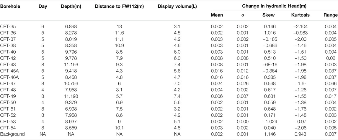
TABLE 1. CPT push details and effect on hydraulic head measurements in FW112.
2.4 Continuous Geochemistry Monitoring Below Depth of Refusal
Continuous geochemistry was measured using an AquaTROLL® 600 multiparameter sonde (In-situ, Fort Collins, Co) measuring groundwater in well FW106, screened from 10.7 -to− 13.7 m below ground surface. Measured parameters include temperature (°C), specific conductivity (µS/cm), dissolved oxygen (mg/L), salinity (ppm), pH, and total suspended solids (ppt) recorded in 10 min intervals with probes calibrated during deployment on day 1.
2.5 Non-Continuous of Geochemistry Above Depth of Refusal
On day 8, CPT boreholes 43, 47, and 49 were completed in close proximity to FW115 and geochemistry effects were measured from FW115 screened from 8.7-to−9.66 m bgs (Figure 2). A multiparameter AquaTROLL® 9500 (In-situ, Fort Collins, Co) was calibrated prior to use and measured temperature (°C), specific conductivity (µS/cm), dissolved oxygen (mg/L), and pH of groundwater pumped peristaltically through a flow cell at a low flow rate of 0.67 ml/s. Three-times the volume of the well was pumped to establish a geochemistry baseline before local penetrometer advancement for CPT boreholes 43, 47, and 49. Measurements were recorded every 500 ml and during significant events like the advancement and retraction of the piezocone and during grouting. On day 11, a non-CPT background measurement of FW115 was completed using the same method, pump rate, and total volume as day 8 with measurements recorded every 500 ml. Mean values of specific conductivity (µS/cm), dissolved oxygen (mg/L), and pH from non-CPT measurements on day 11 were referenced against measurements made during CPT activity on day 8 (Figure 3).
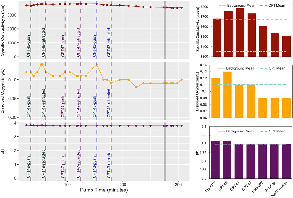
FIGURE 3. Geochemistry measured in FW115 during local cone penetrometer activity shows geochemistry measurements during and following local cone penetrometer activities. Each of the boreholes were grouted around 270 min (gray line). Mean values for CPT activity are plotted in the bar charts on the right with CPT activity mean in teal and mean non-CPT geochemistry background in ash gray.
3 Results
3.1 Geochemistry Effects of CPT
3.1.1 Geochemistry Above Depth of Refusal
On day 8 the penetrometer testing was conducted within a radius of 10 m of FW115 (Figure 2B) at CPT49, 47, and 43 in that order (Figure 3). Prior to the advancement of the piezocone in CPT49, the initial stabilized parameter measurements reported as averages with standard deviations indicate a pre-penetration pH of 3.82 ± 0.01, mean dissolved oxygen concentration of 0.12 ± 0.01 mg/L, and mean specific conductivity of 3,680 ± 15 μs/cm. Figure 3 shows the FW115 days 8 CPT activity parameter means in teal, and the non-CPT background means from day 11 in ash. The means of pH and dissolved oxygen during CPT pushes 49, 47, and 43 on day 8 were not distinct from non-CPT measurements on day 11. Specific conductivity increased during penetration peaking at 3,799 μS/cm during the development of CPT47 (Figure 3). Monitoring in FW115 continued following the final retraction of the piezocone in CPT43 and during the penetration for CPT 39. CPT 39 was abandoned after three attempts when penetration encountered shallow impenetrable material above 3.8 m. For this reason, the final push of day 8 is considered CPT43 after which a negative trend in specific conductivity was observed (Figure 4). The downward trend in specific conductivity was best-fit by the following second-order polynomial regression, y = 1E-05x2—0.0906x + 3,691.4 with an R-squared value of 0.98 where x = volume pumped (ml) at a rate of 0.67 ml/min post-CPT and y = specific conductivity (µs/cm). The negative-trend in specific conductivity following retraction of the piezocone at CPT49 was unaltered by the addition of sodium bentonite (l2H2Na2O13Si4 ) to seal CPT43, 47, and 49 (Figure 4).
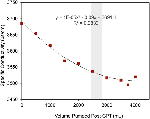
FIGURE 4. Specific conductivity decreased rapidly immediately following the end of the localized cone penetrometer activity including during the addition of the bentonite slurry (gray bar) in CPT 43, 47, and 49.
3.1.2 Continuous Monitoring Geochemistry Below Depth of Refusal
Figure 5 shows that while specific conductivity increased in FW115, no clear deviation from the background was identified during penetration in FW106. The daily variation in specific conductivity during the CPT activity on day 8 and day 9 was 17 μs/cm and 34 μs/cm respectively (Figure 6). Following the completion of penetration activities on days 11 and 12, the site received 5.2 and 2.5 cm of rain respectively resulting in an overall daily variation in specific conductivity which was up to five-times greater than the daily variation measured on day 8 (Figure 6). No distinct changes to dissolved oxygen, dissolved solids, or pH could be identified from continuous monitoring in FW106 during any days of CPT activity (Figure 5).
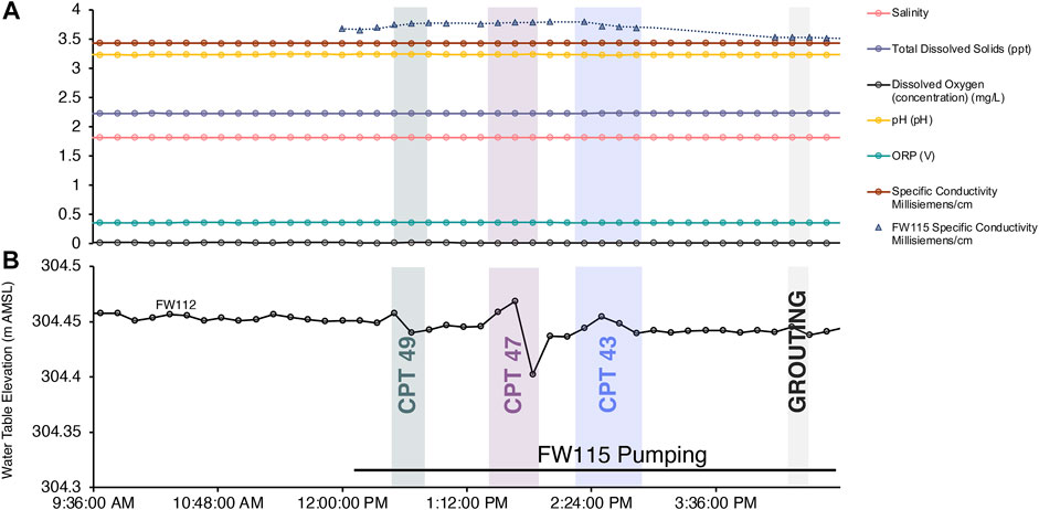
FIGURE 5. Effects of day 8 CPT pushes on geochemistry and water level. (A) shows stable geochemistry from the continuous monitoring in FW106 (round points) while the shallow specific conductivity in FW115 (triangles) increased during penetration. (B) the advancement and retraction of the probes caused water level changes measurable by the 10 min interval data collected in FW112.

FIGURE 6. Groundwater response to rainfall and CPT activity. (A) is the continuous monitoring of specific conductivity in FW106 which shows no change in response based on CPT activity. Rainfall on days and 11 and 12 causes a spike in conductivity that causes ∼300 µs/cm increases the specific conductivity over 48 h. (B) demonstrates a similar trend observed for water level. The solid line in panel B is the mean daily water elevation and the shaded range is the daily standard deviation. Water level variation remains consistently low throughout CPT activity until the rainfall events on days 11 and 12.
3.2 Local Hydrologic Effects
The act of piezocone advancement/retraction displaced a specific volume of material as a product of its depth and the piezocone diameter (Table 1). During advancement of the cone, water displacement during retraction was observed as an increase in local water level, and as a decrease during retraction (Figure 5). No water level change was measured in FW024 or FW103, but was measurable in FW112. The coarse resolution of 10 min interval data do not meet proper assumptions to estimate the rate of response, but do provide a measure of variability in hydraulic head. During CPT47, continuous monitoring in FW112 measured a 0.066 m change in water level, the largest change in water level recorded during this study (Table 1). The 0.066 m range was similar to continuous monitoring data collected during an hour of pumping at a rate of 150 ml/min. (Kelly, 2021) and similar to the water level change following a local rain event (Table 2). For water level changes measured in FW112, categories were assigned to the CPT pushes based on measured distance (radius) from FW112: “1–5 meters,” “5–10 meters,” “15–20 meters,” and an additional category for ‘Background’ water levels collected on days without local penetration activities or rain. Initial interpretations of the data suggested a larger overall change in water level during penetration activities to the South/South West (S/SW) of FW112. Therefore, an additional grouping was applied to the location of the boreholes assigned as either “southerly” or “non-southerly” with all other non-CPT measurements assigned to “Background.” A comparison of means in Table 2 shows that the highest mean difference in hydraulic head is identified from CPT penetration within 1–5 m and 5–10 meters of FW112 with distance range being a significant factor in the measurable response (Table 3). The difference in water level response varied significantly between CPT boreholes (Table 3) and was highest in a region of the study site located to the South/South West of FW112. A Tukey Honest Significant Difference (Tukey HSD) test of the ANOVA results in Table 3 identified penetration activities for 5 pushes; CPT43, 45A, 46A, 47, and 49 were significant over background (p < 0.01). The location of the pushes was also confirmed to be significant over a comparison of CPT pushes based on an ANOVA with a Tukey HSD (Table 4) where the aforementioned significant boreholes made up 5 of the 6 southerly boreholes (Figure 7). When other pushes were within the same radius of FW112, change in water level was not significantly different from background (p < 0.001) (Figure 7). The continuous monitoring devices also captured changes in hydraulic head during rain events at the site on days 12 and 13. The rain events resulted in total water elevation change 0.067 and 0.04 m for days 12 and 13 respectively and increased variability overall (Figure 6).
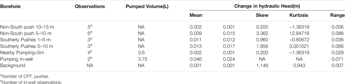
TABLE 2. Change in hydraulic head based on distance and orientation from FW112.

TABLE 3. ANOVA test of changes in hydraulic head (m) based on the distance and orientation of each push from FW112.
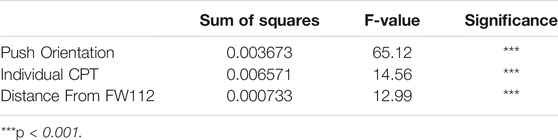
TABLE 4. Tukey Honest Significance Difference test of change in hydraulic head (m) for location of CPT boreholes relative to FW112.
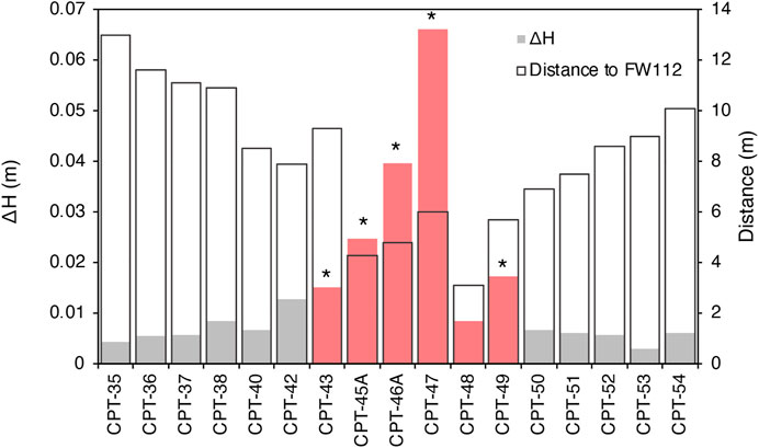
FIGURE 7. Local CPT activity influence on local water levels. Changes in water level (ΔH) measured in FW112 during CPT activity are plotted as shaded bars, and distance between the CPT push and FW112 in transparent. Salmon colored bars indicate penetration activities which occurred South/South West of FW112, and stars (*) indicate those which were identified to have significant (p < 0.01) water level variation from daily values during CPT activity based on an ANOVA test of mean significance.
3.3 Soil Behavior Type Analysis
The two most abundant soil behavior types were both over consolidated sediment behavior types: very stiff fine grained (CH-CL) composing 39.4% of the total, and sand to clayey sand (SC-SM) which made up 18.2% of the total measured intervals. The third and fourth most abundant soil types were sandy silt to clayey silt (ML-MH) accounting for 13.8% and silty sand to sandy silt (SM-ML) accounting for 13% with all other soil types collectively accounting for 15.6% of measured intervals across the saturated subsurface (Figure 8). Similarity in sediment type composition from each CPT log was compared using Euclidean distance and clustered using a complete linkage method (Figure 8). Overall, there is no clear spatial relationship in clusters with only 3 samples clustered with a neighboring sample. Neighboring sample clusters include CPT38 and 42, CPT43 and 45, and CPT46A and 47. The sample clustering shows the high level of variability in soil behavior types. The composition of the two most abundant soil types; very stiff fine grained (CH-CL) and sand to clayey sand (SC-SM) did emerge as a distinguishing characteristic in sample clustering at a high level (Figure 8). The composition of very stiff fine grained (CH-CL) and sand to clayey sand (SC-SM) in cluster A was 39.8 +/− 4.7% and 68.3 +/− 7.3% in cluster B (Figure 8). When a linear model was used to compare the water level response for southerly boreholes 43, 45A, 46A, 47, 48, and 49 to the relative composition of soil behavior types only very stiff fine-grained sediment (CH-CL) showed a linear trend. The linear model produced a multiple R-squared of 0.728, an F-value of 10.74 on 1 and 4 degrees of freedom, and a p-value of 0.03.
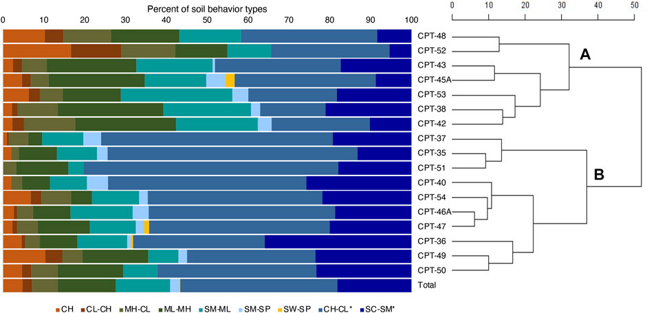
FIGURE 8. Relative abundance of soil behavior types. Samples are ordered based on Euclidean distance calculated from composition of soil behavior types identified in each CPT log. Letters A and B on the hierarchical dendrogram on the right designate clusters A and B which differentiate primarily in the composition of compacted sediments (designated by *). Similar samples will share a branch at a lower score. Soil classifications are based on Robertson (1986).
4 Discussion
The effects of penetration on specific conductivity and water level were only detected above the depth of CPT refusal. The depth of refusal coincides with the depth of material transition from shallow saprolite to weathered bedrock (Watson et al., 2004). The physical act of penetration was the only CPT-associated activity in this study that had a measurable effect on specific conductivity. When sodium bentonite grout was applied there was no measurable effect to pH or specific conductivity despite its high cation exchange potential and a pH of between 8.5 and 10 (Barcelona et al., 1983; Office of Solid Waste and Emergency Response, 1986). The effects of penetration on water level and specific conductivity dissipated rapidly following penetration. Water level and specific conductivity changes were respectively equal to and less than the 24-h measured response from a subsequent rain event which is a common source of perturbation in shallow groundwater systems (Christensen et al., 2018).
The physical act of penetration within 10 m of a monitoring well did displace subsurface material resulting in small water level fluctuations measured at less than or equal to 66 mm. Considerations of this influence on surrounding water levels and their insight into well connectivity may be a comparison to other work related to direct push hydraulic conductivity tests (Butler et al., 2002). A cluster analysis of soil behavior profiles indicated local and site-wide heterogeneity in measurements of soil behavior type and no direct relationship between soil types and water level during penetration. During penetration activities, water level responses were not equal in all directions from the monitoring well and suggest that the variable water level response may be related to soil properties like the fractures in fine grained materials and the preferential flow found in this study site (Watson et al., 2004; Revil et al., 2013). While the resolution of measures in this study are not sufficient to fully determine the characteristics of flow, higher frequency measurements during penetration with a larger diameter device may supplement the use of penetration studies to characterize subsurface material or connectivity (Vienken et al., 2012; American Society for Testing and Materials, 2018). Furthermore, the specific use of soil behavior types can provide estimates of aquifer parameters, but these data alone may not be sufficient for identifying areas of preferential flow during characterization.
In summary, the physical act of penetration has a limited effect on local specific conductivity and water levels. The effects of these activities appear to vary based on the physical characteristics of subsurface materials with a minimal effect overall.
Data Availability Statement
The original contributions presented in the study are included in the article/Supplementary Material, further inquiries can be directed to the corresponding author.
Author Contributions
AP analyzed data and wrote the article. AP and EK were involved with project planning and data collection. MR and KL provided field support and monitoring equipment during penetration testing. TH was involved in analysis of data, project planning, article preparation, and was the PI on the overall project.
Funding
This material by ENIGMA- Ecosystems and Networks Integrated with Genes and Molecular Assemblies a Science Focus Area Program at Lawrence Berkeley National Laboratory is based upon work supported by the United States Department of Energy, Office of Science, Office of Biological & Environmental Research under contract number DE-AC02-05CH11231. Oak Ridge National Laboratory is managed by UT Battelle, LLC, for the United States Department of Energy under contract DE-AC05-00OR22725.
Conflict of Interest
The authors declare that the research was conducted in the absence of any commercial or financial relationships that could be construed as a potential conflict of interest.
Publisher’s Note
All claims expressed in this article are solely those of the authors and do not necessarily represent those of their affiliated organizations, or those of the publisher, the editors and the reviewers. Any product that may be evaluated in this article, or claim that may be made by its manufacturer, is not guaranteed or endorsed by the publisher.
Acknowledgments
We would like to thank Astrid Terry at Lawrence Berkeley National Laboratory and thank Ryan Post and Firas Mishu at M&W drilling and Dennis Stauffer at Fugro for their support and effort in securing contracts to complete this work. This work was made possible by the effort and support of our Radiological Control Technicians Mike Cooke, Joel Miller, and Alex Patton as well as our CPT rig operators Bobby Brandt and Tyrone Sanders. Photographs of activities and equipment were provided by Brett Tate of Y-12 photography.
References
American Society for Testing and Materials (2018). Standard Practice for Using the Electronic Piezocone Penetrometer Tests for Environmental Site Characterization and Estimation of Hydraulic Conductivity. D6067/D6067M-17.
American Society for Testing and Materials (2020). Standard Test Method for Electronic Friction Cone and Piezocone Penetration Testing of Soils. D5778-12.
Barcelona, M. J., Gibb, J. P., and Miller, R. A. (1983). A Guide to the Selection of Materials for Monitoring Well Construction and Ground-Water Sampling. Illinois State Water Survey.
Butler, J. J., Healey, J. M., Mccall, G. W., Garnett, E. J., and Loheide, S. P. (2002). Hydraulic Tests with Direct-Push Equipment. Ground Water 40, 25–36. doi:10.1111/j.1745-6584.2002.tb02488.x
Campanella, R. G., Howie, J. A., Hers, I., Sully, J. P., and Robertson, P. K. (1990). Evaluation of Cone Pressuremeter Tests in Soft Cohesive Soils. Pressuremeters, 125–135.
Christensen, G. A., Moon, J., Veach, A. M., Mosher, J. J., Wymore, A. M., Van Nostrand, J. D., et al. (2018). Use of In-Field Bioreactors Demonstrate Groundwater Filtration Influences Planktonic Bacterial Community Assembly, but Not Biofilm Composition. Plos One 13, e0194663. doi:10.1371/journal.pone.0194663
Doskey, P. V., and Cespedes, E. R. (2006). Cone-penetrometer-deployed Samplers and Chemical Sensors. Encyclopedia Anal. Chem., 129–132. doi:10.1002/9780470027318.a0905m
Hatcher, R. D., Lemiszki, P. J., Foreman, J. L., Dreier, R. B., Ketelle, R. H., Lee, R. R., et al. (1992). Status Report on the Geology of the Oak Ridge Reservation. United States.
Integrated Field-scale Subsurface Research Challenge 2021. Oak Ridge National Laboratory [Online]. Available at: https://www.esd.ornl.gov/orifrc/ [Accessed 2021].
Kelly, E. R. (2021). Influence of Physical Variability of Highly Weathered Sedimentary Rock on Nitrate in Area 3 of the ENIGMA Field Research Site at Y-12. MSc, University of Tennessee.
Malone, P. G., Comes, G. D., Chrestman, A. M., Cooper, S. S., and Franklin, A. G. (1992). Cone Penetrometer Surveys of Soil Contamination. Environ. Geotechnology, 251–257.
Oak Ridge Y-12 Plant, T.N (1995). “Calendar Year 1994 Groundwater Quality Report for the Bear Creek Hydrogeologic Regime,” in Y-12 Plant, Oak Ridge, Tennessee 1994 Groundwater Quality Data Interpretations and Proposed Program Modifications. United States.
Office of Solid Waste and Emergency Response (1986). RCRA Ground-Water Monitoring Technical Enforcement Guidance Document (TEGD). U.S. Environmental Protection Agency. Available at: https://www.epa.gov/sites/default/files/documents/rcragwguiddoc-rpt_0.pdf.
R Core Team (2021). R: A Language and Environment for Statistical Computing. 4.0.1 ed. Vienna, Austria: R Foundation for Statistical Computing.
Revil, A., Skold, M., Karaoulis, M., Schmutz, M., Hubbard, S. S., Mehlhorn, T. L., et al. (2013). Hydrogeophysical Investigations of the Former S-3 Ponds Contaminant Plumes, Oak Ridge Integrated Field Research Challenge Site, Tennessee. Geophysics 78, En29–En41. doi:10.1190/geo2012-0177.1
Robertson, P. K. (1986). In Situ testing and its Application to Foundation Engineering. Can. Geotech. J. 23, 573–594. doi:10.1139/t86-086
Robertson, P. K. (2010). “Soil Behaviour Type from the CPT: an Update,” in 2nd International Symposium on Cone Penetration Testing, 2, 575–583.
Robertson, P. K. (1990). Soil Classification Using the Cone Penetration Test. Can. Geotech. J. 27, 151–158. doi:10.1139/t90-014
Sutton, G., and Field, S. (1995). Distribution of Anthropogenic Fill Material within the Y-12 Plant Area. Oak Ridge, Tennessee. Oak Ridge Y-12 Plant, TN (United States)).
Vienken, T., Leven, C., and Dietrich, P. (2012). Use of CPT and Other Direct Push Methods for (Hydro-) Stratigraphic Aquifer Characterization - a Field Study. Can. Geotech. J. 49, 197–206. doi:10.1139/t11-094
Watson, D., Kostka, J., Fields, M., and Jardine, P. (2004). The Oak Ridge Field Research Center Conceptual Model.
Keywords: hydrogeology, contaminated site, shallow subsurface, cone penetrometer technology (CPT), mixed waste
Citation: Putt AD, Kelly ER, Lowe KA, Rodriguez M and Hazen TC (2022) Effects of Cone Penetrometer Testing on Shallow Hydrogeology at a Contaminated Site. Front. Environ. Sci. 9:821882. doi: 10.3389/fenvs.2021.821882
Received: 24 November 2021; Accepted: 21 December 2021;
Published: 13 January 2022.
Edited by:
Andrew Hursthouse, University of the West of Scotland, United KingdomReviewed by:
Adrian McCallum, University of the Sunshine Coast, AustraliaXiujun Guo, Ocean University of China, China
Copyright © 2022 Putt, Kelly, Lowe, Rodriguez and Hazen. This is an open-access article distributed under the terms of the Creative Commons Attribution License (CC BY). The use, distribution or reproduction in other forums is permitted, provided the original author(s) and the copyright owner(s) are credited and that the original publication in this journal is cited, in accordance with accepted academic practice. No use, distribution or reproduction is permitted which does not comply with these terms.
*Correspondence: Terry C. Hazen, dGNoYXplbkB1dGsuZWR1