- 1School of Engineering, University of Edinburgh, Edinburgh, United Kingdom
- 2SSE Thermal, Reading, United Kingdom
- 3Department of Mechanical Engineering, University of Sheffield, Sheffield, United Kingdom
Demand for low-carbon sources of hydrogen and power is expected to rise dramatically in the coming years. Individually, steam methane reformers (SMRs) and combined cycle gas power plants (CCGTs), when combined with carbon capture utilisation and storage (CCUS), can produce large quantities of on-demand decarbonised hydrogen and power respectively. The ongoing trend towards the development of CCUS clusters means that both processes may operate in close proximity, taking advantage of a common infrastructure for natural gas supply, electricity grid connection and the CO2 transport and storage network. This work improves on a previously described novel integration process, which utilizes flue gas sequential combustion to incorporate the SMR process into the CCGT cycle in a single “combined fuel and power” (CFP) plant, by increasing the level of thermodynamic integration through the merger of the steam cycles and a redesign of the heat recovery system. This increases the 2nd law thermal efficiency by 2.6% points over un-integrated processes and 1.9% points the previous integration design. Using a conventional 35% wt. monoethanolamine (MEA) CO2 capture process designed to achieve two distinct and previously unexplored CO2 capture fractions; 95% gross and, 100% fossil (CO2 generated is equal to the quantity of CO2 captured). The CFP configuration reduces the overall quantity of flue gas to be processed by 36%–37% and increases the average CO2 concentration of the flue gas to be treated from 9.9% to 14.4% (wet). This decreases the absorber packing volume requirements by 41%–56% and decreases the specific reboiler duty by 5.5% from 3.46–3.67 GJ/tCO2 to 3.27–3.46 GJ/tCO2, further increasing the 2nd law thermal efficiency gains to 3.8%–4.4% points over the un-integrated case. A first of a kind techno economic analysis concludes that the improvements present in a CO2 abated CFP plant results in a 15.1%–17.3% and 7.6%–8.0% decrease in capital and operational expenditure respectively for the CO2 capture cases. This translates to an increase in the internal rate of return over the base hurdle rate of 7.5%–7.8%, highlighting the potential for substantial cost reductions presented by the CFP configuration.
Highlights
• Novel thermal integration method for the merging of SMR and CCGT processes into a single “combined fuel and power” (CFP) plant.
• 36%–37% decrease in flue gas to be treated with an increase in average CO2 concentration from 9.9% to 14.4% vol (wet).
• Increase in 2nd law thermal efficiency of 2.6% points over un-integrated processes (1.9% points over previous integration designs) rising to 3.8%–4.4% points over the un-integrated case when CO2 capture is employed.
• 15.1%–17.3% (CAPEX) and 7.6%–8.0% (OPEX) reduction for CO2 capture cases, resulting in a 5.1–5.4%-point increase in the internal rate of return of investment.
1 Introduction
Electricity produced via fossil fuel combustion is expected to continue to play an essential role in future energy grids by proving a sizeable portion of the dispatchable power capacity needed to operate electricity grids with high penetration of intermittent renewable generation (Stark et al., 2020). Likewise, hydrogen may play a role as an energy storage vector when produced via electrolysis at periods of excess renewable generation (green hydrogen). But if required in volumes predicted by 2050 (250-460TWth/pa in the UK) (Stark et al., 2020) this is unlikely to be met exclusively with electrolytic hydrogen due the large build out of renewable capacity and storage systems that would be required to ensure security of supply. As a result, some dispatchable source of hydrogen production will likely be required, with the reforming of methane into hydrogen and CO2 being the most likely candidate (Joffe et al., 2018; UK Gov, 2021b). In both cases, i.e., fossil-based power and hydrogen, these production methods will need to be fully decarbonised in order to be compatible with a net zero energy system.
Post combustion CO2 capture (PCC) is the most technologically mature option for decarbonising natural gas-fired Combined Cycle Gas Turbines (CCGT). Both pre-combustion and post-combustion CCS schemes have been proposed for Steam Methane Reformers (SMR) (Collodi et al., 2017) however, due to the need to supply heat to the reformation cycle, pre-combustion CO2 capture from the high pressure syngas typically only capture ∼60% of the CO2 produced in facility, with further decarbonisation typically reliant on post combustion, either solely, or as a combination of pre and post combustion, or the use of the autothermal reforming (ATR) process over the SMR process.
Although technically mature, PCC is a Capital Expenditure (CAPEX) intensive process. A proposed pathway for decreasing CAPEX is by increasing the CO2 concentration of the flue gas to be treated. This reduces the diameter of the absorber column required to process the same amount of CO2, a major component of total plant CAPEX. As an additional benefit, the increased CO2 concentration can reduce the required height of absorber packing sections, further reducing CAPEX, and/or increase the rich loading of the solvent leaving the absorber column, reducing the specific reboiler duty (SRD).
Models of a CCGT plant fitted with exhaust gas recirculation (EGR) show that a 36% decrease in flue gas flow rate translates to an 40% decrease in the required absorber packing volume and 2.9% reduction in SRD (Herraiz et al., 2018). Separate models indicated that flue gas sequential firing (FGSF) in a CCGT with PCC reduces total plant CAPEX by 15.3% vs. an unfired CCGT for the same power output and CO2 capture rate (González Díaz et al., 2016).
Increased CO2 concentrations and decreased absorber sizes becomes increasingly critical as target CO2 capture fractions increase, previous work by the authors (Mullen et al., 2023; Mullen and Lucquiaud, 2024) has highlighted the importance of increasing CO2 capture fractions up to their economical limit if CCS is to function as a long-term mitigation measure for climate change. This economical limit is, assuming net zero anthropogenic CO2 addition to the atmosphere is the ultimate goal, the point at which the marginal cost of increasing CO2 capture fractions further is above the cost of subsequent atmospheric removal via a permanent negative emission technology. This is a moving goalpost and is not only process, project and geologically specific but also temporally variable as the cost of negative emissions decreases into the future. In leu of a defined optimum point the authors proposed the point at which no additional CO2 is added to the atmosphere from direct operations, termed 100% fossil CO2 capture. The gross CO2 capture fraction across the absorber required to achieve the capture of 100% of the fossil CO2 depends on the ratio of atmospheric CO2 entering the boundary of the plant to the amount of fossil CO2 generated in the process. For a typical CCGT with a CO2 concentration of 4%–5% in the flue gas, a gross CO2 capture fraction across the absorber of 99%–99.2% is required, increasing to 99.6%–99.7% for a Biomass, EfW or coal-fired power plant and 99.8% for an SMR. A key challenge which has been identified when increasing CO2 capture fractions is ensuring that there is sufficient residence time and driving force in the absorber to enable the capture CO2 at very low partial pressures. Along with reduced lean solvent loadings this will also require an increase in absorber packing. Therefore, any increase in flue gas CO2 concentration from FGSF, EGR or others, may have an synergistic relationship with increased CO2 capture fractions as the required increase in absorber packing hight will be mitigated by any reduction due to the increased concentration.
In the case of FGSF, the reduction in CAPEX comes with a reduction in plant thermal efficiency from 51.3% in the unfired case to 43.1% when supplementary firing is implemented. As such, the reduction in plant CAPEX will be offset to some degree by an increase in plant operational expenditure (OPEX). For power generation plants, thermal efficiency is a key driver of economic viability, especially for CCGTs that operate primarily as the marginal power generation source in energy markets. It is then likely that using FGSF in CCGTs producing exclusively electricity will only be economically viable for applications where CO2 demand is very high, such as enhanced oil recovery (EOR).
An alternative approach is to use the additional heat input from the supplementary fuel to drive an endothermic chemical reaction, therefore maintaining the 2nd law efficiency of the power generation and the rated electrical efficiency of the CCGT plant while producing an additional product. The thermal reformation of natural gas and steam into hydrogen can serve this purpose, maintaining power production thermal efficiency, reducing the CAPEX burden of the PCC plant and producing an additional decarbonised energy vector expected to be critical to the decarbonisation of global energy systems (Joffe et al., 2018).
The production of power and hydrogen in a single plant through sequential firing, termed “Combined Fuel and Power” (CFP), will, in addition to any CAPEX and OPEX reductions, also take advantage of the multitude of shared infrastructure requirements between decarbonised CCGT and SMR plants (natural gas supply, electricity grid connection, CO2 transport and storage networks, cooling water, etc.).
The concept of co-generation of hydrogen and power has been previously suggested by Herraiz et al. (2020) who proposed placing the traditional hydrogen reforming process directly into the flue gas path, downstream of sequential burners that re-fire the O2 rich flue gas exiting the gas turbine exhaust. Herraiz et al. (2020) shows that the integration of the reforming and power generation cycles can reduce flue gas flow rates to the PCC plant by circa 34%. Simultaneously increasing the average flue gas CO2 concentration is increased from 10.5 vol% to 16.1 vol% (saturated) when compared to the independent production of each energy vector. This results in a 17.5% reduction in absorber packing volume, a 4.3% reduction in SRD for solvent regeneration and a 5.6% increase in power output, intensifying the CO2 capture process and reducing capital costs. However, the degree of integration between the two processes was minimal, leading to inefficiencies.
There is also at least one operational industrial site where sequentially fired gas turbine flue gas is utilised for steam methane reforming. The Air Products Port Arthur Phase II (IEAGHG, 2018) hydrogen production facility consists of a 80MW GE frame 7EA GT with the flue gas separated into two streams both of which are sequentially combusted using a combination of refinery gas and natural gas. The first stream goes to a HRSG which produces steam for power generation and use in the SMR which is located downstream of the sequential burners in the second flue gas stream, vacuum swing CO2 capture from the high pressure syngas stream is installed however the CO2 present in the flue gas remains uncaptured. This is a promising reference for the co-generation of power and hydrogen, however the limited level of integration between the steam production and hydrogen production, as with Herraiz et al. (2020), leaves substantial room for thermodynamic efficiency gains. Additionally, for the Port Arthur case, the separation of the flue gas into two distinct streams is appears inefficient from both a CAPEX and footprint perspective.
In this work, the authors propose a redesigned heat flue gas and syngas heat recovery system that minimizes exergy destruction in the system by optimizing pinch temperatures and prioritizing HP steam production, fully merging both the CCGT and SMR processes. This redesigned process is predicted to increase the thermal efficiency of the plant relative to the counterfactual Figure 2 and without CO2 capture by 2.6% points and an estimated 1.9% points when compared to Herraiz et al. (2020).
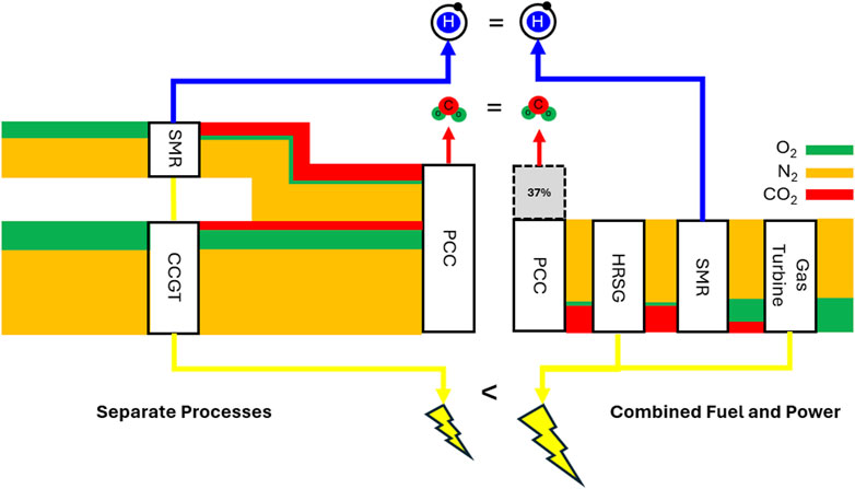
Figure 1 illustrates the process by which the flue gas flow rate reduction achieved in a CFP plant. With sequential firing of the gas turbine flue gas in the burners of an integrated SMR furnace, the mass of CO2 captured (assuming the same fuel requirement) remains the same as the counterfactual (Figure 2) while the reduction in the intake of ambient air leads to a 34% reduction the flue gas mass flow rate into the PCC plant, reducing absorber sizes and CAPEX costs.
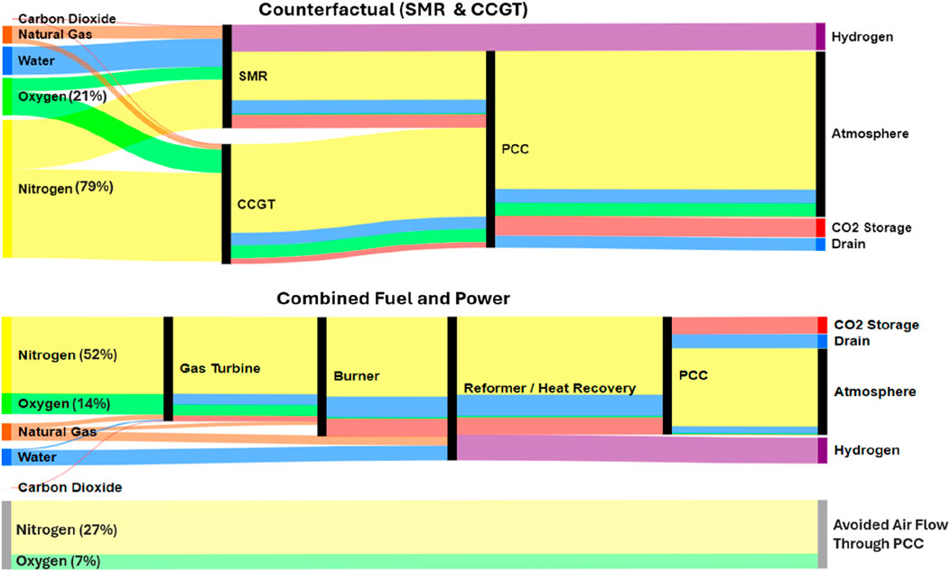
Figure 1. Representation of fluid species flow rates, on a molar basis, though both the counterfactual and combined fuel and power case. Power output not shown electricity will only be economically viable for applications where CO2 demand is very high, such as enhanced oil recovery (EOR).
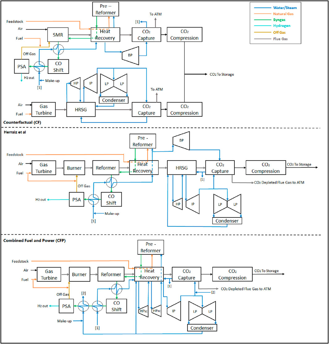
Figure 2. Counterfactual (CF), Herraiz et al. (2020) Configuration and Combined Fuel and Power Plant.
2 Limitations of the study
While the process described in this manuscript proposes one route to the capture of 100% of fossil CO2 from the production of methane-based hydrogen and/or electricity, it is by no means the only route. The learnings present in previous work by the authors (Mullen et al., 2023; Mullen and Lucquiaud, 2024) and others (Su et al., 2023) are broadly applicable to all post combustion applications using an MEA solvent and thus can be applied to alternative power generation facilities such as energy from waste (EfW) or coal.
Likewise, a number of hydrogen production routes exist and may prove competitive for the production of hydrogen with no direct CO2 emissions. This includes SMR schemes where high pressure CO2 is removed from the syngas stream through amine based CO2 capture (Cownden et al., 2023) or alternative methods (Pichot et al., 2017) with PCC applied to the SMR furnace flue gas. Or alternative processes such as autothermal reforming (ATR) (IEAGHG) or molten carbonate fuel cells (Consonni et al., 2021; Barckholtz et al., 2022). However the review and analysis of all low carbon hydrogen production methods is beyond the scope of this manuscript and the reader is referred to (AlHumaidan et al., 2023) for a detailed analysis of fossil based low carbon hydrogen production.
Additionally, the analysis provided in this manuscript covers direct CO2 emissions from the plant only and does not consider upstream or downstream greenhouse gas emissions (GHG), which can have a considerable effect on the lifecycle emissions of the product. The reader is referred to previous work by the authors which provide an analysis of lifecycle methane and CO2 emissions for CCGT’s (Mullen and Lucquiaud, 2024). and SMRs (Mullen et al., 2023).
Finally, the CFP process presented in this work is likely only feasible for new build applications or open cycle gas turbine (OCGT) conversions and is not currently envisioned to be retrofittable to existing CCGTs without complete replacement of the HRSG system. Likewise, no commentary has been provided on any required increase in the maintenance or operational requirements of the proposed CFP plant as this is an unknown for a novel process design, however as a similar process is in operation at the Air Products Port Arthur Phase II (IEAGHG, 2018) hydrogen production facility this is not expected to be excessive.
3 SMR and CCGT integration
The counterfactual in Figure 2 is considered the baseline against which plant performance improvements are measured. In this case both SMR and CCGT processes are maintained separate with dedicated PCC plants feeding into a shared CO2 T&S network in a CCUS “cluster” arrangement, these processes have been described in detail in previous work by the authors (Mullen et al., 2023; Mullen and Lucquiaud, 2024) but do not notably deviate from standard configurations.
Herraiz et al. proposed the installation of an SMR downstream of a GT however the integration of both processes was limited to the sharing of a flue gas path and CO2 capture plant (Figure 2). As commercial GTs operate with a large amount of excess air, O2 is present in the flue gas at a concentration of 10–14 vol%. This is used for the combustion of a mixture of SMR off gases from the hydrogen purification system and supplementary natural gas, providing the additional heat required to drive the exothermic SMR reaction. O2 concentration is reduced to ca. 1 vol% and CO2 concentration increased to ca. 16.5 vol% (saturated at 35°C), resulting in a 36%–37% reduction in flue gas volume relative to the counterfactual. Despite the reduction in flue gas volume and increase in CO2 concentration achieved by the Herraiz configuration, the degree of integration between the two processes is minimal, leading to inefficiencies.
The Combined Fuel and Power (CFP) configuration detailed in this work demonstrates a higher degree of thermal integration with a redesigned heat recovery system for the flue gas and syngas stream. High Pressure (HP) steam production is maximised and a new pre-heating module for the sequential burner fuel is included, both are strategically located to optimise heat recovery and minimise irreversibility’s in the system (see Figure 3). This is in contrast to Herraiz et al. where HP steam is exclusively produced in the HRSG with the SMR producing steam at reformer pressure (25–35 bar), resulting in larger irreversibility due to the high pinch temperatures. The CFP scheme proposes the use of two HP turbine cylinders in parallel. One exhausting the steam at intermediate pressure (IP) for use in further power generation (as in a conventional CCGT), whilst the other exhausts the steam at the reformer pressure (RP) for use in the reforming process. This configuration maintains the reduction in flue gas flow rates observed by Herraiz et al. while also increasing the thermal efficiency of the plant.
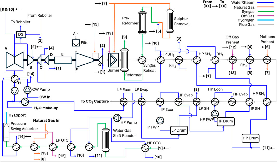
Figure 3. Process flow diagram of the Combined Fuel & Power Plant. A—Low Pressure (LP) turbine, B—Intermediate Pressure (IP) turbine, C—High Pressure (HP) turbine exhausting at reformer pressure, D—High Pressure turbine exhausting at IP, E—Generator, F—Compressor, G—Gas Turbine. Feedwater Pump (FWP), Cooling Water (CW), Once Through Cooler (OTC), Superheat (SH), Economiser (Econ), Evaporator (Evap).
4 Modelling methodology
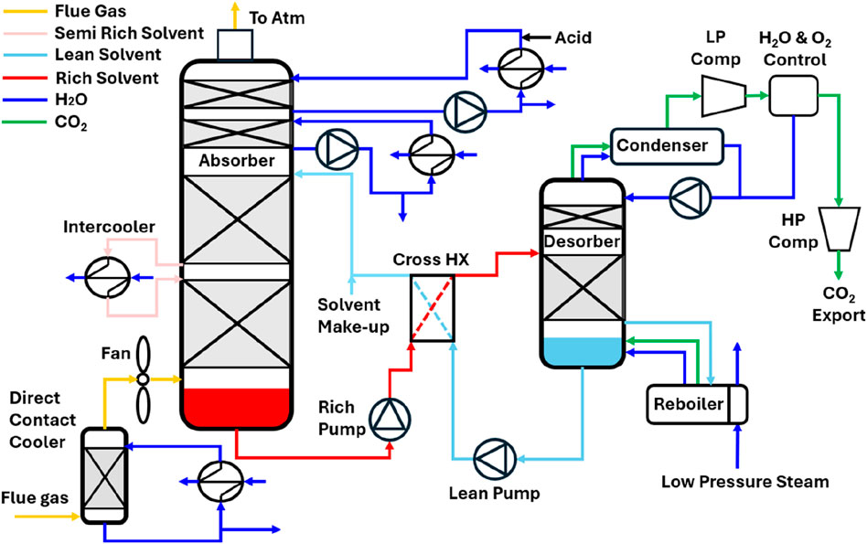
An integrated CFP Plant model has been developed in gPROMS Process Builder (gPROMS, 2021), a process modelling platform that allows the creation of bespoke unit models for each specific plant operation using Peng-Robinson equation of state for gas mixtures and the Scientific Formulation IAPWS-95 for water and steam. The process modelling of the CO2 capture plant is conducted using an open-source MEA model funded by the US Department of Energy and developed by the Carbon Capture Simulation for Industry Impact (CCSI) in ASPEN PLUS (ASPENtech, 2022). This model is validated against pilot-scale data from the US National Carbon Capture Centre (NCCC) (Morgan et al., 2020). The reader is referred to Mullen et al. (2023); Mullen and Lucquiaud (2024) for a detailed description of the process modelling. However, the process does not notably differ from that of a traditional amine CO2 capture plant and is illustrated in Figure 4. All modelling is completed at ISO standard conditions using a natural gas based fuel as described in Supplementary Appendix A. All process assumptions including pressure drops, isentropic efficiencies, etc., are also provided in Supplementary Appendix A.
4.1 Gas turbine
A GE H-Class 1 × 1 combined cycle gas turbine (GE 9HA.01) with a rated thermal efficiency of 63.5% (LHV) is chosen for the basis of design due to the availability of operational parameters in the public domain (Matta et al., 2000; Smith et al., 2000; General Electric, 2016; General Electric, 2017). It should be noted that this technology is not limited to this Gas Turbine (GT) engine and could be applicable to any commercial CCGT plant.
The GE 9HA.01 operates at a pressure ratio of 23.5 and a turbine inlet temperature (TIT) of greater than 1430°C. At ISO ambient conditions, with a natural gas fuel source and 100% load, the GT has a power output of 446MW with a thermal efficiency of 43.1% (LHV). The flue gas exits the GT with a flow rate of 805 kg/s, a temperature of 629°C and ca. 11 vol% O2 concentration. A detailed breakdown of all the design and performance parameters used in the model is presented in Supplementary Appendix A. Hot gas path cooling is achieved by a hybrid system, with closed-loop steam cooling for the 1st and 2nd stage nozzles and compressed air extracted from the GT compressor supplying cooling air for the 3rd stage nozzles. No cooling is required for the 4th stage. Cooling steam is extracted from the HP turbine exhaust and IP superheater as required. The cooling steam passes through the stationary nozzles and is heated to approximately re-heat temperature, where it is then reintroduced to the steam cycle by mixing it with the hot re-heat steam from the HRSG prior to entering the IP turbine.
4.2 Reformer furnace and flue gas heat recovery
Flue gas exiting the GT is sequentially fired using preheated mixture of the off-gas from the hydrogen purification system (containing unreacted natural gas and a small amount of H2) and a controlled amount of supplementary natural gas. This mixture is ignited in the sequential burners, reaching a temperature of 1,550°C and an O2 concentration ca. 1 vol%. It is worth noting that this is the highest temperature seen in the heat recovery section of this plant but is lower than the typical maximum temperatures of 1,800°C for conventional SMRs. Due to the lower adiabatic flame temperature and the larger flue gas flow rate in the CFP configuration, a redesign of the reformer is required to account for a reduction in radiative heat transfer and an increase in convective heat transfer compared to conventional SMR. Nonetheless this is not envisioned to be a substantial technical barrier as convective reformers are commercially available (Topsøe, 2007).
The flue gas passes through the reformer module reducing its temperature to 1,150–1,050°C prior entering the heat recovery section where heat is recovered for the purposes of generating steam, natural gas pre-heating, off gas pre-heating and syngas re-heating. The 6 out of 17 tube banks will likely have to be manufactured from high grade alloys to withstand the higher than standard temperatures. This is already the case for conventional SMRs and is not likely to contribute to a marked CAPEX increase when compared to the counterfactual. The flue gas leaves the heat recovery section at approximately 80°C, which is in line with typical CCGT designs but lower than the 130–140°C typical in SMRs (Collodi et al., 2017).
4.3 Steam cycle
The steam cycle used in this work is a subcritical triple pressure (186/41/3.7 bar) HRSG with re-heat. HP and IP steam temperatures are set at 600°C and 585°C respectively (General Electric, 2017). Feedwater to the steam generators comprises of condensate from the reboiler return and steam cycle condenser with the remainder made up from make-up water. There will be a higher requirement for make-up water in a CFP plant when compared to conventional CCGTs, as a portion of the water is consumed in the reforming and shift reactions. However, the quantity of make-up water is a function of the reforming process and constant across all cases.
Steam for the CO2 capture process is extracted from the IP/Low Pressure (LP) crossover, with additional LP steam supplied via a once through cooler (OTC) fitted to the syngas cooling system. Supplementary HP steam is generated via heat recovery from the reformer syngas stream in a HP OTC. Two HP turbine cylinders are considered in this plant arrangement. The first one, shown in black in Figure 3, acts as the conventional CCGT HP turbine and exhausts steam at IP pressure to the re-heaters. The second one, shown in blue, exhausts steam at the required reformer operating pressure, in this case 34 bar. This is then re-heated in the HRSG up to 500°C for use in the reforming cycle. GT fuel pre-heating is completed in the syngas heat recovery section, removing the need for extraction of IP water from the IP economiser. LP steam for use in various plant applications including de-aeration is generated in the HRSG at 277°C and 3.7 bar. A minimum pinch and approach temperature of 10°C and 15°C respectively was chosen for the steam cycle.
4.4 Reforming process
The reforming cycle used in this model is based on the technical and operational parameters of a conventional SMR with PCC as described in a report commissioned by the IEAGHG in 2017 (Collodi et al., 2017). Modifications were made to the heat recovery process for the purpose of integration into the CFP plant. Steam at 34 bar is extracted from the exhaust of one of the two HP turbine cylinders in parallel (as described in Section 4.4) and used as process steam for methane reforming. This steam is re-heated up to 500°C and mixed with a pre-heated and pre-treated stream of natural gas feedstock at the same temperature and pressure. The ratio of steam to natural gas feedstock entering the pre-reformer is set to give a steam-to-carbon ratio of 2.5 in the reformer. This mixture then enters pre-reformer, which is an adiabatic reactor that converts 100% of the C2+ hydrocarbons and olefins present in the feedstock into CO and H2. After pre-reforming the syngas is re-heated to 600°C prior to entry to the catalyst-filled reformer tubes where steam reacts with methane at ca. 913°C to form a syngas consisting of equilibrium amounts of CH4, H20, H2, CO2 and CO.
Condensate returning from the reboiler of the PCC plant at ∼130°C is pumped to HP turbine inlet pressure and fed through heat exchangers on both sides of the water-gas-shift reactor (WGSR). A HP OTC cools the inlet stream to 320°C while generating HP steam at 600°C and a HP economiser cools the outlet stream to the dew-point temperature at approximately 150°C while heating HP water up to saturation temperature prior to being sent to the HRSG HP drum for evaporation and superheating. The WGSR converts ca. 72% of the CO and the equal number of moles of H2O in the syngas stream to H2 and CO2. Heat recovery from the syngas stream is maximized via, an LP OTC generating LP steam for use in the PCC plant and two additional heat exchangers which preheat Natural Gas and the off-gas from the Pressure Swing Absorber (PSA) hydrogen purification system. Final cooling of the syngas stream to 40°C is completed prior to entry into the PSA for H2 separation.
4.5 2nd law (exergy) analysis
A detailed 2nd law or exergy analysis is conducted for the integration scheme of the proposed CFP plant, with the aim of identifying areas of high exergy generation and areas for process improvements.
The exergy analysis was completed by defining each distinct component in the plant, operating at steady state, as a control volume with adiabatic boundaries. An exergy balance was then completed on each control volume as defined by Equation 1 to determine the degree of irreversibility for that component. Exergy at the inlet to the compressor fine filter was assumed to be zero.
Where:
Subscripts i and e describe the conditions at the inlets and outlets of a control volume respectively, j the conditions at a heat source and o the reference state.
The exergy efficiency of the plant
Where:
4.6 Technoeconomic assessment
A multi-level factorial cost model previously developed and published by the author is used to calculate PCC plant Engineering, Procurement and Construction (EPC) cost with an estimated accuracy of +35%/-15% (AACE Class 4) (Christensen Larry, 2005).
Equipment costs for the CCGT and SMR components of the CFP plant were reverse calculated using Equation 3 from published EPC costs (Murphy and Ferguson, 2018; UK Gov, 2021a) and a suite of economic parameters (Supplementary Appendix B), SMR components were scaled to the appropriate size using Equation 4 and a scaling factor of 0.79 (Sinnott and Towler, 2020). A conservative assumption that all SMR equipment in a standard SMR will be used in the CFP was applied. The equipment costs factor in Equation 3 was taken as the summation of the CCGT and Scaled SMR equipment. In practice it is likely that equipment costs will be somewhat reduced as equipment is shared between processes. Equation 3 was then used to calculate the total CFP EPC cost and Equation 5 used to estimate a total plant CAPEX.
Where
4.6.1 Net present value (NPV) and internal rate of return (IRR)
The net present value (NPV) of an asset is the present value of all the future cash flows (positive and negative) that asset will generate (Equation 6), all future cashflows are discounted using a defined discount rate.
A positive NPV indicates that an asset is predicted to return greater profitability than an alternative investment at the applied discount rate. The Internal Rate of Return (IRR) is the discount rate that makes the NPV of a project zero. i.e., it is the expected compound annual rate of return that will be earned on a project or investment. Business will typically apply a “hurdle rate” to a project which defines the minimum acceptable IRR from an investment and is highly dependent on the perceived risk, i.e., a low-risk investment would be expected to have a lower hurdle rate than a high-risk investment1,2.
The levelised cost of a product, i.e., electricity (LCOE) or hydrogen (LCOH) is the average net present cost of a unit of a product over the lifetime of the asset for a given IRR. Or in other words, the present value average minimum price of a product that will provide the required return on investment. An estimate LCOE and LCOH for an IRR of 7.8% (Menmuir et al., 2022) is available in Mullen et al. (2023) and Mullen and Lucquiaud (2024) for CCGTs and SMRs at a range of CO2 capture rates and is summarised in Table 1.

Table 1. Levelised cost of electricity and hydrogen (Mullen et al., 2023; Mullen and Lucquiaud, 2024) for a three CO2 capture fractions.
The values provided in Table 1 are used to assess the profitability of a CFP plant compared to hydrogen and electricity production in dedicated SMRs and CCGTs (i.e., the counterfactual in this study) by assuming that they operate in the same market. Therefore, the LCOE and LOCH serves as an estimate for the average minimum sale price for each product from the CFP. The resultant NPV of the CFP plant and associated change in IRR is reported.
5 Results and discussion
5.1 Thermal performance of the CFP plant
The thermal performance of the CFP plant and counterfactual, i.e., segregated operation of a CCGT and SMR, is presented in Table 2, in this instance without CO2 capture to demonstrate the increase in thermal efficiency occurring as a result of the thermal integration.
Marginally higher quantities of natural gas fuel are required in the CFP plant compared to the counterfactual to reduce levels of excess O2 in the flue gas down to 1% vol. Nevertheless, the higher level of thermal integration and optimised heat recovery system from both the flue and syngas streams results in a marked increase in electrical output of 128MW, leading to an increase in 2nd law thermal efficiency of 2.6% points over the counterfactual and 1.9%-point increase over the previous integration design by Herraiz et al. Further comparisons to Herraiz et al. are not feasible for the remainder of this manuscript as the CO2 capture plant modelling techniques diverge and would not represent a valid comparative basis.
5.2 Performance with CO2 capture integration
The performance of the counterfactual and CFP cases with CO2 capture at two distinct CO2 capture fractions, 95% gross CO2 capture and 100% fossil CO2 capture, is presented in Table 33.
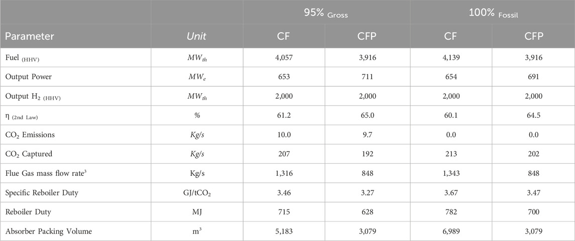
Table 3. Comparison of the Combined Fuel and Power Plant (CFP) performance with CO2 capture with the Counterfactual (CF) shown in Figure 2.
The CFP plant is shown to have a 36%–37% reduction in saturated flue gas flow rate to the absorber depending on the CO2 capture fraction considered. This results in a 56%–41% reduction in the volume of absorber packing required. The increase in net CO2 concentration of the flue gas into the absorber results in a 5.5% decrease in specific reboiler duty (SRD). This, along with the increased thermal efficiency of the CFP process results in an increase in the 2nd law thermal efficiency of 3.8%–4.4% points over the counterfactual. A detailed breakdown of the outputs of the CO2 capture plant modelling is available in Supplementary Appendix C.
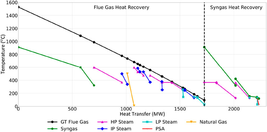
Figure 5 details the heat recovery from the sequentially fired GT flue gases and the syngas stream for the CFP plant at a 100% fossil CO2 capture fraction. It is evident that the temperatures directly downstream of the sequential burners are higher than those typically seen in CCGTs. They are, however, marginally lower than those seen in conventional SMRs, suggesting that this would not cause a marked change in capital costs when compared to the counterfactual. Downstream from the off-gas pre-heater, the flue gas temperatures are more typical of those seen in CCGT’s (González Díaz et al., 2016) and as such standard construction materials and manufacturing techniques can be used.
5.3 Exergy analysis
A detailed exergetic analysis is completed for the counterfactual and CFP plants to identify areas of high exergy destruction and aid in the design of the CFP process. Figure 6 demonstrates the quantity and location of the exergetic efficiency gains realised.
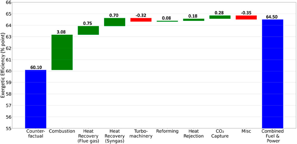
Figure 6. Exergetic efficiency gains in Combined Fuel and Power process compared to the Counterfactual.
The primary location of improvement is in the combustion system downstream of the GT, which serves as the SMR burners which contributes over 3% of the 4.4% improvements. Due to the high flue gas flow rate these burners operate at a lower adiabatic flame temperature than traditional SMRs resulting in less exergy destruction. The lower flame temperature also facilitates a reduction in pinch temperatures between the reformer model and the flue gas, allowing a modest reduction in exergy destruction. Further improvements were realised through the optimised heat recovery system in the flue gas and syngas streams, minimising pinch temperatures and prioritising HP steam generation where possible. Lower flue gas temperatures leaving the heat recovery system aided efficiency gains while the reduced energy requirement of the CO2 capture plant was the final process improvement realised.
Any increased rates of exergy destruction were seen primarily as a result of the higher demand on the turbo machinery (i.e., steam turbines) and increased absolute auxiliary loads.
5.4 Technoeconomic analysis
A detailed technoeconomic analysis as described in Section 4.6 has been completed and presented in Table 4.

Table 4. Technoeconomic analysis. Levelised Cost of Hydrogen and Power from Mullen et al. Net present value of the combined fuel and power plant set to zero and resultant increase in internal rate of return reported.
A 15.1%–17.3% decrease in total plant CAPEX is predicted as a result of the reduced flue gas flow rate while increases in efficiency leads to a net reduction in plant OPEX of 7.6%–8.0%. By assuming that the CFP operates in the same energy market as CCGTs and SRMs and therefore has an average product sale price equivalent to the LCOE and LOCH electricity and hydrogen, respectively. The residual NPV of the CFP plant is M£1,621 and 1,763 for the 95% gross CO2 capture and 100% fossil CO2 capture cases respectively at the assumed hurdle rate for similar energy projects (Menmuir et al., 2022). When this NPV is incorporated into the TEA (i.e., is set to zero) it results in a predicted IRR of 12.9% and 13.2% for the CFP plant, a marked increase of 5.1% and 5.4% over the counterfactual (7.8%).
The analysis presented does not present a LCOH, or LCOE, for the CFP, plant as it is assumed to operate in the same market as the CF, and any additional profit generated directly increases the IRR., The dual product nature of the CFP, prohibits calculation of both the LCOH and LCOE, as evaluation of the levelized cost for one product requires a fixed, and in the absence of a market defined fixed price, arbitrary, price for the other
6 Conclusion
A novel thermal integration configuration for the co-generation of low to zero-carbon hydrogen and power in a single combined fuel and power (CFP) plant with post combustion CO2 capture (PCC) operating at two distinct CO2 capture fractions is investigated:
• 95% gross, considered the minimum permittable in the UK
• 100% fossil, wherein the CO2 generated in the plant is equal to the quantity of CO2 captured
The concept of co-generation of hydrogen and power has been previously suggested by Herraiz et al. (2020), placing the traditional hydrogen reforming process directly into the flue gas path downstream of sequential burners that re-fire the O2 rich flue gas exiting the gas turbine exhaust. However, the degree of integration between the two processes was minimal, leading to inefficiencies. In this work, the authors propose a redesigned heat flue gas and syngas recovery system that minimizes exergy destruction in the system by optimizing pinch temperatures and prioritizing HP steam production, fully merging both the CCGT and SMR processes. This redesigned process is predicted to increase the thermal efficiency of the plant relative to the counterfactual, i.e., an independent CCGT and SMR, by 2.6% points and an estimated 1.9% points when compared to Herraiz et al.
When PCC is employed, flue gas volumes to the CO2 capture plant are reduced in the CFP by 36%–37%, relative to the counterfactual. This is the result of all viable O2 in the incoming combustion air being consumed in the combustion process, thereby avoiding the treatment of excess N2 as is typical for CCGTs. Concurrent to the reduction flue gas flow rate, the increase in net CO2 concentration to be treated in the CO2 capture plant [9.9%–14.4% vol (wet)] is estimated to reduce the specific reboiler duty by 5.5% This, along with the increased thermal efficiency of the CFP process increases the 2nd law thermal efficiency by 3.8%–4.4% points over the counterfactual.
In addition to the novel integration design, this manuscript quantifies, for the first time, the cost reduction potential of the CFP configuration through a rigorous technoeconomic analysis, an essential advancement over the previous work but Herraiz et al. The reduction in flue gas flow rate and increase in thermal efficiency is predicted to result in a 15%–17% decrease in total plant CAPEX and 7.6%–8.0% reduction in plant OPEX for a 95% gross and 100% fossil CO2 capture fraction, respectively. By assuming that the CFP plant operates in the same energy market as CCGTs and SMRs these CAPEX and OPEX reductions are predicted to translate to a 5.1% and 5.4% increase in the predicted internal rate of return over the counterfactual, representing a substantial increase in profitability.
From the presented work it is clear that the described CFP process presents a large opportunity for cost reductions in the production of low to zero carbon power and hydrogen by using opportunistic synergies arising from the deployment of CCS in large industrial clusters.
Data availability statement
The raw data supporting the conclusions of this article will be made available by the authors, upon request.
Author contributions
DM: Conceptualization, Data curation, Formal Analysis, Investigation, Methodology, Visualization, Writing–original draft, Writing–review and editing. ML: Conceptualization, Funding acquisition, Project administration, Resources, Supervision, Validation, Writing–review and editing.
Funding
The author(s) declare that financial support was received for the research, authorship, and/or publication of this article. Funding provided by the School of Engineering at the University of Edinburgh.
Conflict of interest
DM is employed by SSE Thermal.
The remaining authors declares that the research was conducted in the absence of any commercial or financial relationships that could be construed as a potential conflict of interest.
Generative AI statement
The author(s) declare that no Generative AI was used in the creation of this manuscript.
Publisher’s note
All claims expressed in this article are solely those of the authors and do not necessarily represent those of their affiliated organizations, or those of the publisher, the editors and the reviewers. Any product that may be evaluated in this article, or claim that may be made by its manufacturer, is not guaranteed or endorsed by the publisher.
Supplementary material
The Supplementary Material for this article can be found online at: https://www.frontiersin.org/articles/10.3389/fenrg.2024.1511996/full#supplementary-material
Footnotes
1Output of the counterfactual is the summation of the CCGT and SMR models.
2Coefficient of Power (thermal energy vs. the electrical energy that could be extracted) of steam for solvent regeneration is not provided in Herraiz et al., in lieu of this a COP of is assumed and net power output calculated.
3Saturated at 40°C.
References
AlHumaidan, F. S., Absi Halabi, M., Rana, M. S., and Vinoba, M. (2023). Blue hydrogen: current status and future technologies. Energy Convers. Manag. 283, 116840. doi:10.1016/j.enconman.2023.116840
ASPENtech (2022). ASPEN PLUS V10. The orginisation. Available at: https://www.aspentech.com/en/products/engineering/aspen-plus.
Barckholtz, T. A., Taylor, K. M., Narayanan, S., Jolly, S., and Ghezel-Ayagh, H. (2022). Molten carbonate fuel cells for simultaneous CO2 capture, power generation, and H2 generation. Appl. Energy 313, 118553. doi:10.1016/j.apenergy.2022.118553
Christensen Larry, P. D. (2005). Cost estimate classification system – as applied in engineering, procurement, and construction for the process industries, tcm framework: 7.3 – cost estimating and budgeting. Fairmont, WV: AACE.
Collodi, G., Azzaro, G., Ferrari, N., and Santos, S. (2017). Techno-economic evaluation of deploying CCS in SMR based merchant H2 production with NG as feedstock and fuel. Energy Procedia 114, 2690–2712. doi:10.1016/j.egypro.2017.03.1533
Consonni, S., Mastropasqua, L., Spinelli, M., Barckholtz, T. A., and Campanari, S. (2021). Low-carbon hydrogen via integration of steam methane reforming with molten carbonate fuel cells at low fuel utilization. Adv. Appl. Energy 2, 100010. doi:10.1016/j.adapen.2021.100010
Cownden, R., Mullen, D., and Lucquiaud, M. (2023). Towards net-zero compatible hydrogen from steam reformation – techno-economic analysis of process design options. Int. J. Hydrogen Energy 48 (39), 14591–14607. doi:10.1016/j.ijhydene.2022.12.349
Elliott, B., et al. (2018). Retrofitting an Australian Brown coal power station with post-combustion capture - a conceptual study. Bechtel Infrastructure Power Corp.
Gale, J. (2017). Evaluating the costs of retrofitting CO2 captured in an integrated oil refinery: technical design basis and economic assumptions. Hatherley Lane, Cheltenham: IEA Greenhouse Gas R&D Programme. Available at: https://ieaghg.org/publications/technical-reports/reports-list/10-technical-reviews/923-2017-tr5-evaluating-the-costs-of-retrofitting-co2-captured-in-an-integrated-oil-refinery-technical-design-basis-and-economic-assumptions.
González Díaz, A., Sánchez Fernández, E., Gibbins, J., and Lucquiaud, M. (2016). Sequential supplementary firing in natural gas combined cycle with carbon capture: a technology option for Mexico for low-carbon electricity generation and CO 2 enhanced oil recovery. Int. J. Greenh. Gas Control 51, 330–345. doi:10.1016/j.ijggc.2016.06.007
gPROMS (2021). gPROMS products: gPROMS PROCESSBUILDER. Available at: https://psenterprise.com/products/gproms/processbuilder.
Herraiz, L., Fernández, E. S., Palfi, E., and Lucquiaud, M. (2018). Selective exhaust gas recirculation in combined cycle gas turbine power plants with post-combustion CO2 capture. Int. J. Greenh. Gas Control 71, 303–321. doi:10.1016/j.ijggc.2018.01.017
Herraiz, L., Lucquiaud, M., Chalmers, H., and Gibbins, J. (2020). Sequential combustion in steam methane reformers for hydrogen and power production with CCUS in decarbonized industrial clusters. Front. Energy Res. 8 (180). doi:10.3389/fenrg.2020.00180
Joffe, D., et al. (2018). Hydrogen in a low-carbon economy. Comm. Clim. Change. Available at: http://www.theccc.org.uk/publications (Accessed: August 18, 2024).
Matta, R. K., Mercer, G. D., and Tuthill, R. S. (2000). Power systems for the 21st century - ‘H’ gas turbine combined-cycles, GER-3935B. Schenectady: GE power systems.
Menmuir, D., et al. (2022). Review of next generation carbon capture technology for industrial, waste and power sectors. Glasgow: Department for Business, Energy and Industrial Strategy. Available at: https://www.gov.uk/government/publications/review-of-next-generation-carbon-capture-technology-for-industrial-waste-and-power-sectors.
Morgan, J. C., Chinen, A. S., Anderson-Cook, C., Tong, C., Carroll, J., Saha, C., et al. (2020). Development of a framework for sequential Bayesian design of experiments: application to a pilot-scale solvent-based CO2 capture process. Appl. Energy 262, 114533. doi:10.1016/j.apenergy.2020.114533
Mullen, D., Herraiz, L., Gibbins, J., and Lucquiaud, M. (2023). On the cost of zero carbon hydrogen: a techno-economic analysis of steam methane reforming with carbon capture and storage. Int. J. Greenh. Gas Control 126 (103904), 103904. doi:10.1016/j.ijggc.2023.103904
Mullen, D., and Lucquiaud, M. (2024). On the cost of zero carbon electricity: a techno-economic analysis of combined cycle gas turbines with post-combustion CO2 capture. Energy Rep. 11, 5104–5124. doi:10.1016/j.egyr.2024.04.067
Murphy, J., and Ferguson, S. (2018). Assessing the cost reduction potential and competitiveness of novel (next generation) UK carbon capture technology, benchmarking state-of-the-art and next generation Technologies. Shinfield Park, Reading: Amec Foster Wheeler Group. Available at: https://assets.publishing.service.gov.uk/government/uploads/system/uploads/attachment_data/file/864688/BEIS_Final_Benchmarks_Report_Rev_4A.pdf.
Pichot, D., Granados, L., Morel, T., Schuller, A., Dubettier, R., and Lockwood, F. (2017). Start-up of port-jérôme CRYOCAP™ plant: optimized cryogenic CO2 capture from H2 plants. Energy Procedia 114, 2682–2689. doi:10.1016/j.egypro.2017.03.1532
Sinnott, R., and Towler, G. (2020). Chemical engineering design. 6th edn, chemical engineering. 6th edn. Elsevier. doi:10.1016/C2017-0-01555-0
Smith, R. W., et al. (2000). Advanced technology combined cycles, GER-3936a. Schenectady: GE power systems. Available at: https://www.gevernova.com/content/dam/gepower-new/global/en_US/downloads/gas-new-site/resources/reference/ger-3936a-advanced-technology-combined-cycles.pdf (Accessed August 18, 2024).
Stark, C., et al. (2020). The sixth carbon budget: the UK’s path to net zero, UK carbon budgets. Comm. Clim. Change. Available at: https://www.theccc.org.uk/publication/sixth-carbon-budget/.
Su, D., Herraiz, L., Lucquiaud, M., Thomson, C., and Chalmers, H. (2023). Thermal integration of waste to energy plants with Post-combustion CO2 capture. Fuel 332, 126004. doi:10.1016/j.fuel.2022.126004
Topsøe, H. (2007). BorsodChem mchz - 6,000 nm3/h htcr topsoe hydrogen plant, A case story: 18 Months from engineering to operation. The organisation. Available at: https://www.readkong.com/page/borsodchem-mchz-czech-republic-6-000-nm3-h-htcr-tops-e-4132361 (Accessed August 18, 2024).
UK Gov (B) (2021a). Hydrogen production costs 2021. Whitehall, London: Department for Business, Energy and Industrial Strategy. Available at: https://www.gov.uk/government/publications/hydrogen-production-costs-2021.
UK Gov (D) (2021b). UK hydrogen strategy. London: Department for Business, Energy and Industrial Strategy. Available at: https://www.gov.uk/government/publications/uk-hydrogen-strategy.
Keywords: Carbon capture and storage, blue hydrogen, net zero, CCGT power plant, post combustion capture, decarbonisation
Citation: Mullen D and Lucquiaud M (2024) Thermodynamic integration in combined fuel and power plants producing low carbon hydrogen and power with CCUS. Front. Energy Res. 12:1511996. doi: 10.3389/fenrg.2024.1511996
Received: 15 October 2024; Accepted: 27 November 2024;
Published: 18 December 2024.
Edited by:
Federica Raganati, National Research Council (CNR), ItalyReviewed by:
Timothy A. Barckholtz, ExxonMobil Technology and Engineering, United StatesOzge Yuksel Orhan, Hacettepe University, Türkiye
Mohsen Karimi, University of Porto, Portugal
Copyright © 2024 Mullen and Lucquiaud. This is an open-access article distributed under the terms of the Creative Commons Attribution License (CC BY). The use, distribution or reproduction in other forums is permitted, provided the original author(s) and the copyright owner(s) are credited and that the original publication in this journal is cited, in accordance with accepted academic practice. No use, distribution or reproduction is permitted which does not comply with these terms.
*Correspondence: Daniel Mullen, ZGFuaWVsbXVsbGVuOTJAZ21haWwuY29tJiN4MDIwMGE7
 Daniel Mullen
 Mathieu Lucquiaud