- 1State Grid Zaozhuang Power Supply Company, Zaozhuang, China
- 2School of Electrical Engineering, Shandong University, Jinan, Shandong, China
As the proportion of renewable energy generation continues to rise, the study of voltage source converter (VSC) control has become a focal point of research. The concepts of emulating the characteristics of synchronous machines have led to the proposals of droop control and virtual synchronous control (VSG). However, a deeper comparison of the control characteristics of these two methods is still needed, particularly in terms of their ability to support the system when partial power sources experience fault conditions. This paper analyzes and compares the two in terms of control principles and small-signal modeling, and finally, based on a nine-bus system with 100% renewable energy generation, two scenarios are designed: a sudden load increase and a partial power source disconnection. The differences in control characteristics between the two are compared and analyzed. The results indicate that the VSG exhibits greater damping compared to droop control and is capable of providing inertial support to the system, making its frequency and voltage less susceptible to change.
1 Introduction
In the 21st century, global warming has emerged as one of the most pressing challenges faced by humanity. This phenomenon not only poses a threat to the earth’s ecosystems and biodiversity but also exerts profound impacts on the global economy, social stability, and human health (Gernaat et al., 2021; Xie et al., 2024a; Sun et al., 2021a; Xie et al., 2024b; Sun et al., 2023). In response to this crisis, the international community is actively engaged in the pursuit of sustainable solutions, among which enhancing the proportion of renewable energy generation as a substitute for conventional fossil fuel-based power generation has emerged as a key strategy (Olabi and Ali Abdelkareem, 2022; Mai et al., 2014; Haegel and Kurtz, 2022). According to Renewable Capacity Statistics 2024, the global additional installed capacity for photovoltaic (PV) power generation in 2023 reached 345.5 GW, while the additional installed capacity for wind power generation was 115.97 GW. In comparison to the year 2022, the year-on-year growth rate of the installed capacity for photovoltaic power generation was 22%, and for wind power generation, it was 9% (International Renewable Energy Agency (IRENA), 2024).
With the rapid proliferation of renewable energy generation within power systems, the inherent volatility and randomness of these new energy sources pose significant challenges to the secure and stable operation of the grid. voltage source converters (VSCs), as pivotal interfacing devices between renewable energy sources and the power grid, have garnered considerable attention (Li et al., 2016; Sun et al., 2021b; Xiao et al., 2024a; Martínez-Parrales et al., 2021). To address the aforementioned challenges, numerous VSC control strategies have been proposed, which can be broadly classified into two categories: GFL and GFM controls (Xiao et al., 2024b; Bhatta et al., 2024; Ducoin et al., 2023). GFL, lacking the capability to establish a grid, finds it difficult to provide support to the power network. In contrast, GFM, independent of phase-locked loop (PLL) for generating phase angle, possesses the ability to form an independent power grid, thus attracting increasing scrutiny. Among the various GFM control strategies, the most representative are the virtual synchronous generator (VSG) control and the droop control method (Verbe et al., 2021; Li et al., 2020; Song et al., 2021; Li et al., 2017).
While VSG emulates the characteristics of a synchronous generator through control means, enabling functions such as primary frequency modulation, damping, inertia support, and voltage regulation to provide frequency or voltage support to the system, it is also capable of directly responding to the rate of change of frequency (ROCOF) in the system, which is a primary advantage of VSG control over droop control. Despite some scholars summarizing the differences between the two (Chen et al., 2023; Mohammed et al., 2024; Meng et al., 2019), a detailed comparative analysis of their control characteristics and support capabilities for the system is still lacking.
For the existing research problems, this paper conducts a comparative analysis of the control characteristics of VSG and droop control within a nine-bus system based on 100% renewable energy generation. The contributions of this paper could be summarized as.
(1) The typical control architecture and control principle of GFL and GFM are introduced, and the existing typical control methods of GFM and GFL are summarized.
(2) A detailed introduction and comparison of the control principles of VSG and droop control are provided, highlighting the fundamental mechanisms that govern their operation and interaction with the power grid.
(3) The paper conducts a small-signal modeling analysis of both VSG and droop control strategies, comparing their stability margins and dynamic responses to disturbances, which is crucial for understanding their impact on system reliability.
(4) Utilizing the PSCAD/EMTDC simulation platform, which is recognized for its ability to model and simulate complex power systems with high fidelity, the paper simulates the nine-bus system under various operational conditions. This simulation-based approach allows for a direct comparison of the control characteristics and system support capabilities between VSG and droop control strategies, offering insights into their respective strengths and limitations in a renewable energy-dominated grid.
The remainder of the paper is organized as follows: Section 2 presents the principles of VSG and droop control. Section 3 conducts the small-signal modeling. Section 4 designs the simulation experiments and analyzes the simulation results. Section 5 provides the conclusions.
2 Introduction to GFL and GFM
The synchronization mode of the GFL is to measure the phase information of the parallel node through the phase-locked loop as the reference of the reference voltage phase, so as to realize the “following” of the power grid, which generally shows the characteristics of current source. The GFM must rely on a strong AC power grid to work normally. When the power grid strength is weak, the output current has a great impact on the terminal voltage, which is easy to lead to the instability of the grid following power supply under large/small disturbances. The synchronization mode of grid converter is similar to that of synchronous machine. It adjusts the frequency of reference voltage through power exchange with the grid, so as to achieve synchronization with the grid. On the whole, it shows voltage source characteristics externally. Network type control does not need phase locked loop, and has the ability to independently construct voltage and frequency. It can be applied to provide stable AC voltage in weak current network or even isolated network scenarios.
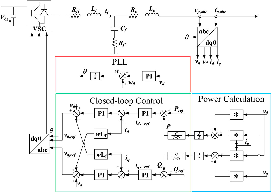
The typical GFL control for power calculation is shown in Figure 1, which can be mainly divided into three parts: PLL, power outer loop current inner loop double closed loop control, and power calculation. PLL tracks and combines the voltage phase of the node, generates the phase angle, and converts three-phase AC electrical quantities such as voltage and current into two-phase direct flow through Parker transform to calculate the active and reactive power output by VSC. The accurate control of VSC output active and reactive power is realized through the power outer loop, and the current inner loop ensures that VSC will not have overcurrent. Control performance can be improved by adding additional controls such as droop control.
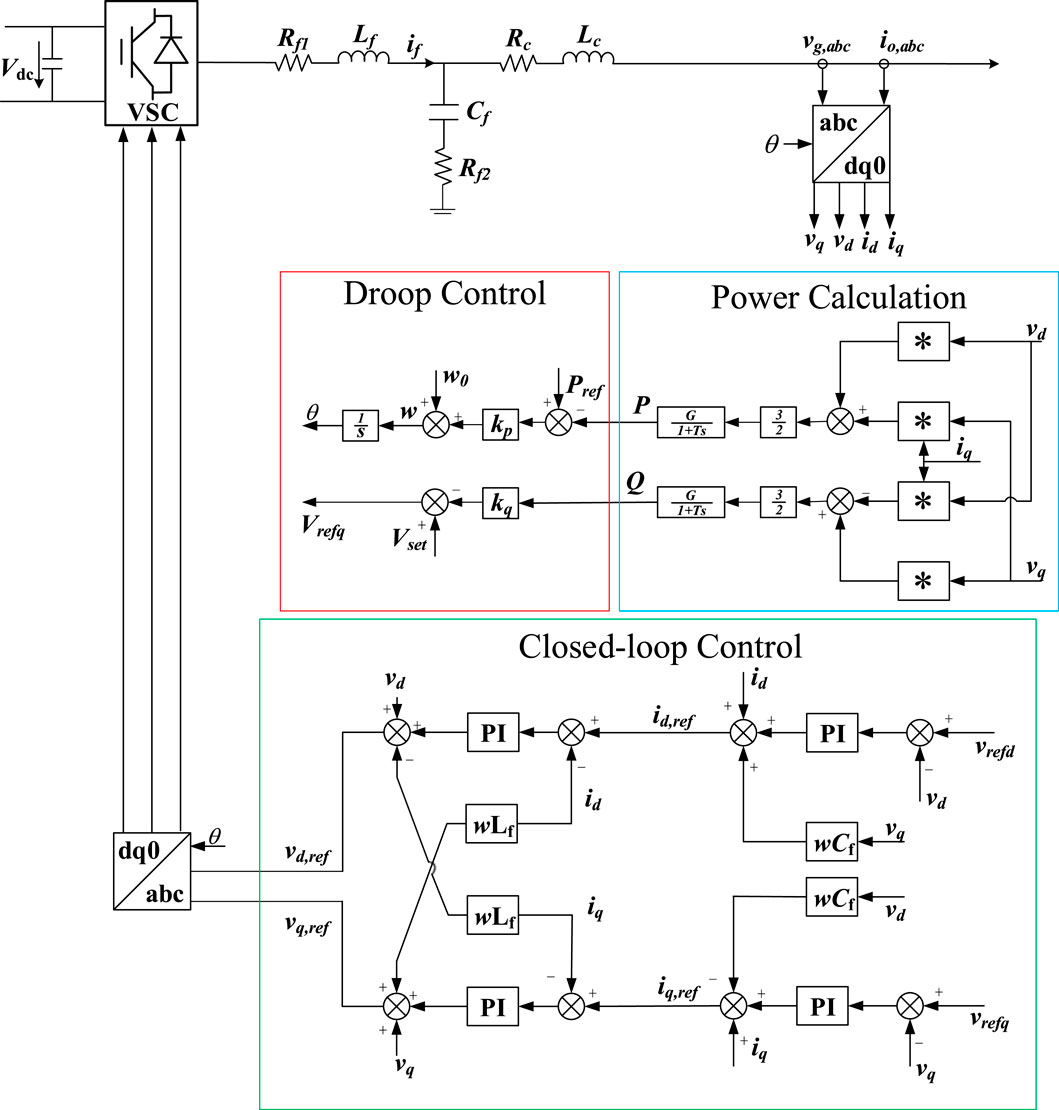
The biggest difference between GFM and GFL is that GFM does not rely on PLL to realize grid connection. The control architecture can be divided into three parts: phase angle generation, power calculation, voltage outer loop current inner loop double closed loop control. The actual output power is obtained through power calculation, and the phase angle is generated by the difference between the actual output power and the target power and the set active power and frequency coupling relationship. The target voltage is generated through the double closed-loop control of voltage outer loop and current inner loop. It is worth mentioning that on this basis, additional control such as reactive power voltage droop can be added to improve the control performance. The typical control architecture of GFM is shown in Figure 2.
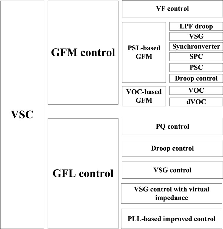
At present, typical VSC control can be divided into GFM and GFL. GFM control includes typical VF control, VOC Control and GFM control based on PSL, among which VSG and droop control are the most widely used. GFL control includes PQ control, droop control, VSG control and other GFL controls with additional control strategies. As shown in Figure 3.
3 VSG and droop control principle
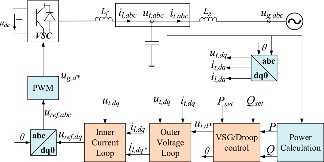
The GFM control structure employing droop/VSG control is depicted in Figure 4. On one hand, the filter capacitor voltage and the filter inductor current are subjected to the Park transformation, converting the three-phase AC quantities into two-phase DC quantities. On the other hand, these quantities are fed into the power calculation module to compute the active and reactive power outputs. The active power (P), reactive power (Q), active power setpoint (Pset), and reactive power setpoint (Qset) are then delivered to the GFM outer loop control (VSG/droop control) to generate the phase angle (θ) and voltage amplitude (utd*). After passing through the classical double-loop control comprising an outer voltage loop and an inner current loop, the target voltages (uref,dq) are produced. These are then transformed back to the three-phase target voltages (uref,abc) via an inverse Park transformation, and finally, pulse-width modulation (PWM) is utilized to generate the gate control signals, thereby completing the control process.
3.1 Droop control architecture and principle
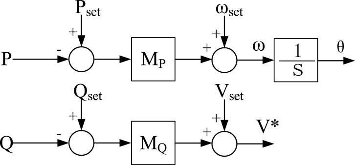
The typical droop control equations for active power-frequency (P-f) and reactive power-voltage (Q-V) are shown in Equation 1.
where ωset, Vset, Pset, and Qset represent the set points for frequency, voltage, active power, and reactive power, respectively. MP and MQ are the droop coefficients for active power and reactive power, respectively, while ω and V* are the frequency and voltage outputs of the droop control, respectively. The control framework is illustrated in Figure 5.
3.2 VSG control architecture and principle
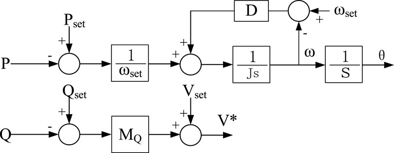
The typical VSG control’s active power-frequency (P-f) equation is depicted in Equation 2.
where ωset is the set value of rotational self angular velocity, ω is the rotor angular velocity, Pset is the power set value, P is the active power output value, J is the rotational inertia, D is the damping coefficient. Mp and Mq denote the droop coefficients for active and reactive power, while ω and V* are the frequency and voltage outputs of the VSG control, respectively. The reactive power-voltage equation for VSG control can be analogous to that of the droop control. The corresponding control block diagram is illustrated in Figure 6.
Comparing Figures 5, 6, it can be observed that both droop control and VSG control achieve self-synchronization through power, specifically by adjusting the frequency of the reference voltage in response to the deviation of active power from its set point. However, there is a distinct difference between the two: droop control possesses only primary frequency modulation capabilities, whereas the presence of inertia J in VSG endows it with inertial characteristics in the dynamics of power and frequency, and damping D provides it with the capability to dampen power oscillations. Regarding reactive power-voltage regulation, both employ the deviation of reactive power from its set point to adjust the output voltage, which allows for the use of an identical control structure and exhibits an active voltage regulation characteristic akin to that of a synchronous machine.
4 Small-signal model of VSG and droop control
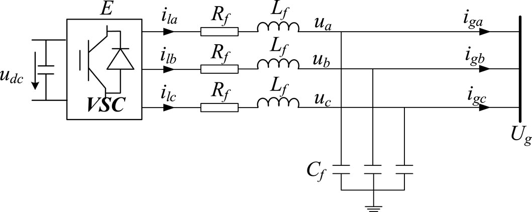
The development of small-signal models for both droop control and VSG control is essential for elucidating their control characteristics and discerning their principal differences. As illustrated in Figures 7, 8. These models facilitate a detailed analysis of the dynamic responses under small perturbations, which is pivotal for the design and optimization of control algorithms within a power system. By comparing the small-signal models of droop control and VSG, one can gain insights into the inherent advantages and limitations of each control strategy. This analysis is particularly relevant in the context of the evolving electric grid, where the interplay between traditional and renewable energy sources necessitates sophisticated control mechanisms to ensure seamless and stable power delivery. The VSC grid connection topology is shown in Figure 9, where E is the VSC voltage and Ug is the voltage of the parallel node.
4.1 Small-signal model of VSG
Let the voltage phase angle at the point of common coupling be set to 0°, at which condition Equation 3 is satisfied, where θ represents the phase of the VSC electromotive force, and δ denotes the power angle, which is equal to θ. The rotor mechanical equation is as shown in Equation 2.
Based on the VSC grid-tied topology as depicted in Figure 9, the active and reactive power output from the VSC to the grid is obtained, as shown in Equation 4.
where Z is the filter impedance and α is the impedance angle, as shown in Equation 5.
Considering that the VSC filter inductance is much larger than the impedance, and the power angle δ is very small, simplify Equation 4 and get Equation 6.
The closed-loop transfer function of the active power control loop for the VSG is presented in Equation 7.
The characteristic root, oscillation frequency and damping ratio of the transfer function can be easily obtained, as shown in Equations 8, 9. The VSG small signal model is depicted in Figure 7.
Through the aforementioned analysis, it is observed that as the rotational inertia J increases, the natural oscillation frequency ωn and the damping ratio of the second-order system decrease, leading to more intense oscillations and a longer time to reach stability. Conversely, as the damping coefficient D increases, the natural oscillation frequency ωn remains unchanged, while the damping ratio increases, resulting in a smoother response curve and a shorter time to stabilize.
4.2 Small-signal model of droop control
The power droop control equation is shown in Equation 10. The grid connected topology of VSC remains unchanged, so the circuit power equation remains unchanged.
The closed-loop transfer function of the active power control loop for the droop control is presented in Equation 11.
By comparing the small-signal models, it can be concluded that droop control exhibits faster dynamic response compared to VSG control, while VSG provides greater damping.
5 Case study
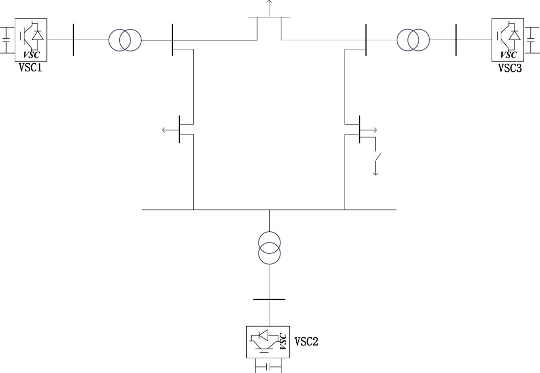
A simulation based on a nine-bus system powered entirely by renewable energy sources was conducted, with two operational scenarios designed: a sudden load increase and a power source disconnection. The system topology is illustrated in Figure 10. VSC1 was configured to employ either droop control or VSG control. The control characteristics and differences between the two were analyzed.
In the initial state, VSC1 employs a GFL control strategy with droop control, while VSC2 utilizes a GFM control strategy with droop control. VSC3 has the option to operate under either a GFM control strategy with droop control or a VSG based GFM control strategy.
5.1 Sudden load increase
Configure VSC3 to operate under both droop control and VSG control. At the 7-s mark of system operation, the load-carrying switch in Figure 10 is closed, resulting in a sudden load increase of 30 MW. Compare and analyze the variations in active power, frequency, and voltage under the two control modes.
Based on the simulation results depicted in Figure 11, when the sudden load increase occurs, the change of the active power generated by VSG control and droop control is basically the same, while the frequency change under VSG control is smaller, and the frequency change is larger when droop control is used. At the same time, the voltage sag under VSG control is smaller than that under droop control.
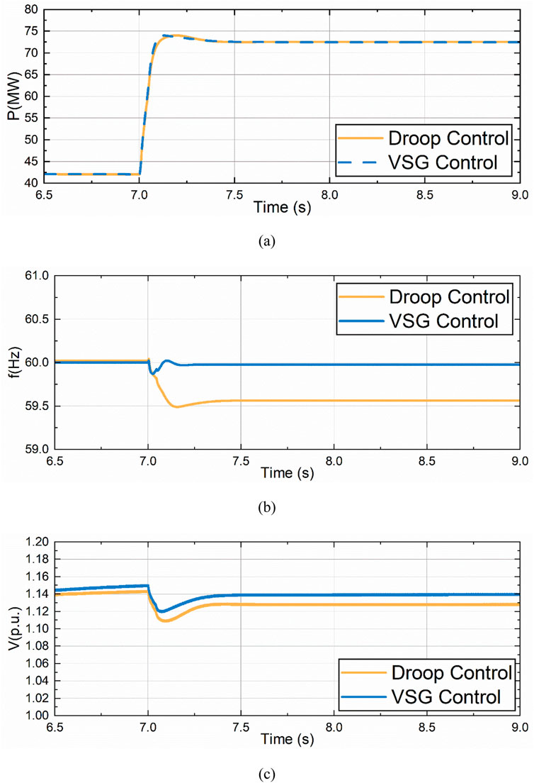
Figure 11. Comparison of drop control and VSG control under sudden load increase. (A) Active Power Variation of VSC3. (B) Frequency Variation of VSC3. (C) Voltage Variation of VSC3.
5.2 Partial power disconnection
Set VSC2 to exit from operation in case of disconnection fault at 7S. VSC3 adopts VSG control and droop control respectively, and compares and analyzes the changes of active power, frequency and voltage under the two control modes.
Based on the simulation results as shown in Figure 12, it can be concluded that similar conclusions can be drawn under the condition of sudden load increase. When a power supply breaks down and exits the operation, the remaining GFM will bear the load originally borne by the fault power supply. The variation of active power generated by VSG control and droop control is basically the same, while the frequency variation under VSG control is smaller, and the frequency variation is larger when droop control is adopted. At the same time, the voltage sag under VSG control is smaller than that under droop control.
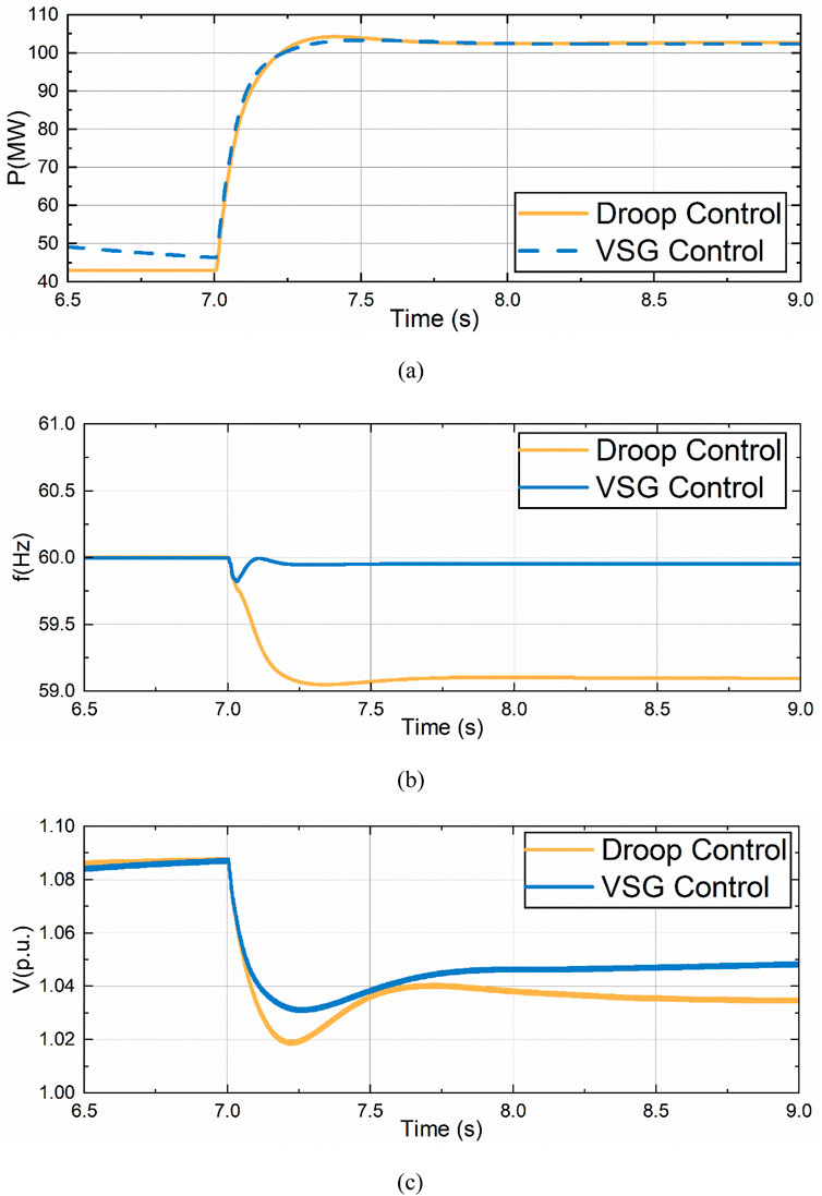
Figure 12. Comparison of drop control and VSG control under partial power disconnection. (A) Active Power Variation of VSC3. (B) Frequency Variation of VSC3. (C) Voltage Variation of VSC3.
This is consistent with the expected results. VSG control has greater damping, can provide inertia support, and frequency and voltage are more difficult to change.
6 Conclusion
In conclusion, this paper has delivered a comprehensive comparison of VSG and droop control within a fully renewable energy-powered nine-bus system. The study has highlighted that VSG control offers enhanced damping, greater stability in frequency and voltage, and crucial inertia support, outperforming droop control. These findings are significant for power system stability, especially with the increasing integration of renewable energy sources. The insights from this research can guide future developments in power system control, emphasizing the potential of VSG control in maintaining grid reliability amidst the energy transition.
Data availability statement
The raw data supporting the conclusions of this article will be made available by the authors, without undue reservation.
Author contributions
KL: Writing–original draft. XL: Writing–original draft. SZ: Writing–original draft. LW: Writing–original draft. QL: Writing–original draft. KW: Writing–original draft. SS: Writing–original draft.
Funding
The author(s) declare that financial support was received for the research, authorship, and/or publication of this article. This work was supported by Science and Technology Project of State Grid Shan-dong Electric Power Company (No. 520610230003).
Conflict of interest
Authors KL, XL, SZ, LW, QL, and KW were employed by State Grid Zaozhuang Power Supply Company.
The remaining author declares that the research was conducted in the absence of any commercial or financial relationships that could be construed as a potential conflict of interest.
The authors declare that this study received funding from Science and Technology Project of State Grid Shan-dong Electric Power Company. The funder had the following involvement in the study: research design, data collection and analysis, publication decisions, and manuscript preparation.
Generative AI statement
The author(s) declare that no Gen AI was used in the creation of this manuscript.
Publisher’s note
All claims expressed in this article are solely those of the authors and do not necessarily represent those of their affiliated organizations, or those of the publisher, the editors and the reviewers. Any product that may be evaluated in this article, or claim that may be made by its manufacturer, is not guaranteed or endorsed by the publisher.
References
Bhatta, S., Alattas, B., Olumide, A., Field, T. E., Peterson, M., and Rastgoufard, P. (2024). “Comparative analysis of grid-following (GFL) and grid-forming (GFM) inverter models for studying low inertia power systems,” in 2024 IEEE Kansas power and energy conference (KPEC). Manhattan, KS, USA, 1–5.
Chen, S., Sun, Y., Hou, X., Han, H., Fu, S., and Su, M. (2023). Quantitative parameters design of VSG oriented to transient synchronization stability. IEEE Trans. Power Syst. 38 (5), 4978–4981. doi:10.1109/tpwrs.2023.3293016
Ducoin, E. A. S., Gu, Y., Chaudhuri, B., and Green, T. C. (2023). “Swing equation modelling of GFL inverter and comparison of its damping and inertia with GFM inverter,” in 19th international conference on AC and DC power transmission (ACDC 2023). Glasgow, UK, 108–114.
Gernaat, D. E. H. J., Sytze de Boer, H., Daioglou, V., Yalew, S. G., Müller, C., and van Vuuren, D. P. (2021). Climate change impacts on renewable energy supply. Nat. Clim. Change 11, 119–125. doi:10.1038/s41558-020-00949-9
Haegel, N. M., and Kurtz, S. R. (2022). Global progress toward renewable electricity: tracking the role of solar (version 2). IEEE J. Photovoltaics 12 (6), 1265–1272. doi:10.1109/jphotov.2022.3206532
International Renewable Energy Agency (IRENA) (2024). Renewable capacity statistics 2024. Abu Dhabi: IRENA.
Li, B., Jing, F., Jia, J., and Li, B. (2016). Research on saturated iron-core superconductive fault current limiters applied in VSC-hvdc systems. IEEE Trans. Appl. Supercond. 26 (7), 1–5. doi:10.1109/tasc.2016.2601649
Li, B., Li, Q., Wang, Y., Wen, W., Li, B., and Xu, L. (2020). A novel method to determine droop coefficients of DC voltage control for VSC-mtdc system. IEEE Trans. Power Deliv. 35 (5), 2196–2211. doi:10.1109/tpwrd.2019.2963447
Li, D., Zhu, Q., Lin, S., and Bian, X. Y. (2017). A self-adaptive inertia and damping combination control of VSG to support frequency stability. IEEE Trans. Energy Convers. 32 (1), 397–398. doi:10.1109/tec.2016.2623982
Mai, T., Hand, M. M., Baldwin, S. F., Wiser, R. H., Brinkman, G. L., Denholm, P., et al. (2014). Renewable electricity futures for the United States. IEEE Trans. Sustain. Energy 5 (2), 372–378. doi:10.1109/tste.2013.2290472
Martínez-Parrales, R., Fuerte-Esquivel, C. R., Alcaide-Moreno, B. A., and Acha, E. (2021). A VSC-based model for power flow assessment of multi-terminal VSC-hvdc transmission systems. J. Mod. Power Syst. Clean Energy 9 (6), 1363–1374. doi:10.35833/mpce.2021.000104
Meng, X., Liu, J., and Liu, Z. (2019). A generalized droop control for grid-supporting inverter based on comparison between traditional droop control and virtual synchronous generator control. IEEE Trans. Power Electron. 34 (6), 5416–5438. doi:10.1109/tpel.2018.2868722
Mohammed, N., Udawatte, H., Zhou, W., Hill, D. J., and Bahrani, B. (2024). Grid-forming inverters: a comparative study of different control strategies in frequency and time domains. IEEE Open J. Industrial Electron. Soc. 5, 185–214. doi:10.1109/ojies.2024.3371985
Olabi, A. G., and Ali Abdelkareem, M. (2022). Renewable energy and climate change. Renew. Sustain. Energy Rev. 158, 112111. doi:10.1016/j.rser.2022.112111
Song, S., McCann, R. A., and Jang, G. (2021). Cost-based adaptive droop control strategy for VSC-mtdc system. IEEE Trans. Power Syst. 36 (1), 659–669. doi:10.1109/tpwrs.2020.3003589
Sun, K., Qiu, W., Dong, Y., Zhang, C., Yin, H., Yao, W., et al. (2023). WAMS-based HVDC damping control for cyber attack defense. IEEE Trans. Power Syst. 38 (1), 702–713. doi:10.1109/tpwrs.2022.3168078
Sun, K., Qiu, W., Yao, W., You, S., Yin, H., and Liu, Y. (2021b). Frequency injection based HVDC attack-defense control via squeeze-excitation double CNN. IEEE Trans. Power Syst. 36 (6), 5305–5316. doi:10.1109/tpwrs.2021.3078770
Sun, K., Xiao, H., Pan, J., and Liu, Y. (2021a). VSC-HVDC interties for urban power grid enhancement. IEEE Trans. Power Syst. 36 (5), 4745–4753. doi:10.1109/tpwrs.2021.3067199
Verbe, S. C., Shigenobu, R., and Ito, M. (2021). “Comparative study of GFM-grid and GFL-grid in islanded operation,” in 2021 IEEE PES innovative smart grid technologies - asia (ISGT asia). Brisbane, Australia, 1–5.
Xiao, H., Gan, H., Yang, P., Li, L., Li, D., and Hao, Q. (2024b). Robust submodule fault management in modular multilevel converters with nearest level modulation for uninterrupted power transmission. IEEE Trans. Power Deliv. 39 (2), 931–946. doi:10.1109/tpwrd.2023.3343693
Xiao, H., He, H., Zhang, L., and Liu, T. (2024a). Adaptive grid-synchronization based grid-forming control for voltage source converters. IEEE Trans. Power Syst. 39 (2), 4763–4766. doi:10.1109/tpwrs.2023.3338967
Xie, X., Ding, Y., Yuanyuan, S., Zhang, Z., and Fan, J. (2024a). A novel time-series probabilistic forecasting method for multi-energy loads. Energy 306, 132456. doi:10.1016/j.energy.2024.132456
Keywords: VSC, VSG, droop control, GFM, renewable energy
Citation: Li K, Lin X, Zhu S, Wang L, Li Q, Wang K and Song S (2024) Comparison of support strategies for grid construction after failure of renewable energy power generation system. Front. Energy Res. 12:1511218. doi: 10.3389/fenrg.2024.1511218
Received: 14 October 2024; Accepted: 06 November 2024;
Published: 27 November 2024.
Edited by:
Wei Qiu, Hunan University, ChinaReviewed by:
Zhengfa Zhang, The University of Tennessee, Knoxville, United StatesHuangqing Xiao, South China University of Technology, China
Guangsheng Pan, Southeast University, China
Copyright © 2024 Li, Lin, Zhu, Wang, Li, Wang and Song. This is an open-access article distributed under the terms of the Creative Commons Attribution License (CC BY). The use, distribution or reproduction in other forums is permitted, provided the original author(s) and the copyright owner(s) are credited and that the original publication in this journal is cited, in accordance with accepted academic practice. No use, distribution or reproduction is permitted which does not comply with these terms.
*Correspondence: Shuxin Song, MjAyMzM0NzU0QG1haWwuc2R1LmVkdS5jbg==
 Ke Li1
 Shuxin Song