- 1Inner Mongolia Electric Economy and Technology Academy, Hohhot, China
- 2School of Energy and Environmental Engineering, Hebei University of Technology, Tianjin, China
Introduction: Heating is one of the main factors leading to high energy consumption and serious carbon emissions in buildings. The clean heating system formed by the coupling of phase change building maintenance structure and solar heating system can improve the thermal storage density of the building maintenance structure, while reducing energy consumption in winter while maintaining a comfortable room temperature through stable energy security.
Methods: Therefore, a phase change radiation terminal heating (PCRTH) system with the phase change radiation module as the terminal and the solar energy and air energy as the clean heat source is established in this study. Nanjing, Tianjin and Shenyang in China were selected as the study zones which correspond to the hot summer and cold winter zone, the cold zone and the severe cold zone respectively. The operational effect of the PCRTH system in different climate zones was studied, and the parameters of the PCRTH system were optimized by the GenOpt program combined with Hooke-Jeeves optimization algorithm.
Results: The analysis results show that the cascade phase change radiation terminals in the three zones reduced room temperature fluctuation, energy consumption and carbon dioxide emissions, but the heating cost was higher. After the Hooke-Jeeves optimization algorithm was used to optimize the PCRTH system parameters in three zones, the PCRTH system heating cost was reduced, and the PCRTH system energy consumption and PCRTH system carbon dioxide emissions were further reduced.
Discussion: Therefore, the building heating system composed of PCM maintenance structure and renewable energy has great application advantages in maintaining a comfortable room temperature and improving heating system energy conservation and environmental protection.
1 Introduction
Energy plays a key strategic role strategic role in modern society, but the consumption of non-renewable energy dominated by fossil fuels is increasing, leading to a serious energy crisis worldwide (Wei et al., 2024; Canelli et al., 2024). Meanwhile, large-scale energy consumption also brings serious environmental pollution and greenhouse effects, which intensifies soil erosion and land desertification (Mughal et al., 2022). Therefore, the all-round optimization and upgrading of energy infrastructure has become a top priority for all countries and zones. Although the replacement of traditional fossil fuels by renewable energy is the main measure to promote the reform of energy structures, the energy structure dominated by fossil fuels cannot be changed in the short term. In 2021, global primary energy demand increased by 5.8% year-on-year, even by 1.3% compared with 2019, which was the largest increase in history and changed the downward trend of energy demand in 2020 (Mughal et al., 2022). The rise in energy consumption has brought about an increase in carbon emissions. Global carbon emissions in 2021 increased by 5.7%, reaching 39 billion tons of carbon dioxide (CO2). Among them, carbon emissions from energy consumption increased by 5.9% year-on-year, reaching 33.9 billion tons of CO2, close to the level of carbon emissions in 2019. With the end of global epidemic prevention and the recovery of economic activity, global energy consumption and carbon emissions have begun to rebound, while the global carbon emissions are still growing, and a lot of fossil fuels are still needed. The global energy pattern is currently undergoing a profound change, characterized by the transformation towards renewable energy and the increasing emphasis on sustainability (Zhang et al., 2021). Countries are gradually adopting clean energy technologies to reduce carbon emissions and fossil fuel consumption. (Khan et al., 2012; Kong et al., 2020; Wang et al., 2022).
The construction field is one of the key industries to realize energy savings and emission reduction. Building carbon emissions can be divided into direct carbon emissions, indirect carbon emissions and implied carbon emissions (Chen et al., 2024). Direct carbon emissions are derived from fossil fuels directly consumed during construction or operation, which is mainly produced in activities such as building cooking, hot water and decentralized heating (Ma et al., 2022). Indirect carbon emissions are the carbon emissions caused by electricity and heat consumed in the operation stage of the building, which is the main source of carbon emissions. Implicit carbon emissions (Belfiori and Rezai, 2024) are the carbon emissions caused by building construction and building materials production. The sum of the first two items is called building operation carbon emissions, and the sum of all three items is called building life cycle carbon emissions. Therefore, in the context of huge building energy consumption, the application of renewable energy to building energy conservation is an inevitable development trend. The building operation stage is an important relief to realize energy savings and emission reduction in the construction field.
Energy consumption in buildings is huge, and renewable energy is an inevitable development trend in building energy conservation. Accelerating the popularization of heating with solar energy bioenergy (Karschin and Geldermann, 2015) and geothermal energy (Zhang et al., 2024) as the main energy sources can not only replace traditional energy sources, but also improve the quality of life and residential comfort of urban and rural residents and greatly reduce the consumption of traditional primary energy. Among them, solar energy can be directly used in building heating, and has shown the advantages of low operating costs and outstanding economic benefits. China is rich in solar energy resources. Two-thirds of the Chinese zones have annual sunshine hours of more than 2,200 h, and the annual solar radiation is more than 5000 MJ/m2 (Li and Huang, 2020). As a device to absorb solar radiation and transfer the generated heat energy to the heat transfer medium, solar collectors have been widely used in building heating, industrial heating, carbon planting, breeding and other fields. Solar heating is a clean and environment-friendly form of energy, which is conducive to reducing energy consumption and operating costs of building heating systems. However, solar energy is intermittent and unstable, which has led to the discontinuity and fluctuation of solar heating. The thermal storage solar heating system collects solar energy through a solar collector and stores it in a thermal storage device on sunny days in winter (Hiris et al., 2022). When solar heating is insufficient, the thermal storage device releases the stored heat to ensure indoor comfort. The heating system of a solar coupled heat storage technology can be divided into solar building systems using the building itself as the heat storage body and solar heating system with a heat storage device alone. Solar energy building systems allow the building itself to collect, store and distribute solar energy in winter through the rational arrangement of building orientation and surrounding environment, clever layout of internal and external space of the building, reasonable selection of envelope structure and building materials, and improved comfort for indoor personnel. Solar building systems can be divided into passive and active types (Ralegaonkar and Gupta, 2010). Passive solar building systems are based on the premise of not using mechanical equipment to transfer heat to the room, so that the building can make full use of solar radiation heat for heating in winter, store heat through the envelope, and meanwhile reduce the heat loss caused by ventilation and infiltration, thus achieving the purposes of indoor environmental comfort, energy savings and emission reduction (Singh et al., 2021). Active solar energy building system stores the collected solar energy resources in the building envelope through photothermal conversion with the help of external driving forces to meet the building heating demand and achieve the purpose of reducing primary energy consumption.
The combination of the solar energy heating system and building envelope indicates significant progress toward sustainable building design. The combination of the solar energy heating system and building envelope indicates significant progress toward sustainable building design (Wang et al., 2022). The solar energy heating system uses the abundant solar energy to provide heat for buildings, which provides a renewable and environmentally friendly alternative to traditional heating methods. At the same time, the building envelope, as the interface between indoor and outdoor environment, plays a vital role in heat preservation and energy saving (Zhao et al., 2023). The combination of solar heating technology and innovative building envelope design can maximize the capture and utilization of solar energy and minimize the loss of heat to the surrounding environment (Ahmed et al., 2022). This collaborative approach not only reduces dependence on non-renewable energy, but also improves the comfort of residents. Therefore, this heating method is helpful to create a more sustainable building environment.
Although the traditional building envelope is very important in providing structural integrity and environmental isolation, it is usually difficult to effectively adjust the room temperature and reduce thermal fluctuations (Wang et al., 2022; Cai et al., 2021; Rathore et al., 2022; Li et al., 2022). However, the addition of phase change material (PCM) provides a promising solution to this challenge. The PCM can effectively adjust the room temperature by absorbing and releasing heat during the phase change process, thus reducing the need for the mechanical heating system (Ahmed et al., 2022; Diaconu et al., 2023; Lawag and Ali, 2022; Maturo, et al., 2023; Faraj et al., 2021). This improves the thermal comfort of residents. Another benefit of PCM is its energy-saving potential. The PCM maintenance structure can reduce dependence on traditional energy, thus reducing system energy consumption and its impact on the environment. Radwan A proposed a new radiant cold plate with multi-segment ceiling style, and compared the temperature distribution difference between radiant cold plate with phase change material and traditional radiant cold plate using software simulation (Sharma et al., 2015). Research showed that radiant cold plates with PCM achieved higher temperature uniformity and better cooling ability on the radiant surface. Larwa B conducted experimental research and COMSOL Multiphysics numerical simulation research on the radiant heating system with PCM in the phase change energy storage floor (Larwa et al., 2021). The research showed that adding PCM above the heating pipe emits more heat. Improving the thermal conductivity of PCM can improve the overall heating performance of phase change energy storage radiant floors.
The cascade PCM maintenance structure is a new method used to improve the thermal performance and energy efficiency of building (Christopher et al., 2021; Panchal et al., 2022; Kishore et al., 2022; Shen, et al., 2024). The traditional building envelope usually adds phase change materials evenly throughout the entire structure, while the strategy of the cascade PCM maintenance structure is to place different PCM in the different areas of the building envelope (Kong et al., 2023). This innovative structure allows targeted thermal regulation in the building areas where temperature fluctuations are most obvious. The cascade PCM maintenance structure can optimize thermal comfort and minimize energy consumption, by changing the distribution of PCM in different parts of the building envelope (Du et al., 2023). However, the initial investment of composite heating system is higher and energy supply mode which varies randomly with the daily solar irradiation makes the configuration and operation control of the system more complex. Therefore, in order to evaluate the composite heating system comprehensively, it is necessary to carry out optimization research. The most researches have devoted to parametric study, where each design parameter was varied while the rest of parameters were fixed, meanwhile, there are conflicts between some evaluating indicators. But the multi-objective optimization method could be effectively conducted into the problem.
This research introduced a cascade phase change radiation terminal heating system combining the solar energy and the air source heat pump. The air source heat pump can make up for the intermittent heating shortage of solar energy. The roof and floor of the building were designed with PCM maintenance structures with different phase change temperatures, which increased the energy storage density of the building maintenance structure and reduced the room temperature fluctuation and system energy consumption. Three typical cities in three climatic zones of China were selected as the location of the PCRTH system. The performance of the system was simulated and analyzed by TRNSYS software, and the comprehensive performance of the PCRTH system in different climate zones was explored. The PCRTH system parameters were optimized based on Hooke-Jeeves optimization algorithm. This study provided a reference for the operation design of clean heating system combined with PCM maintenance structure in different climate zones in China.
2 PCRTH system introduction
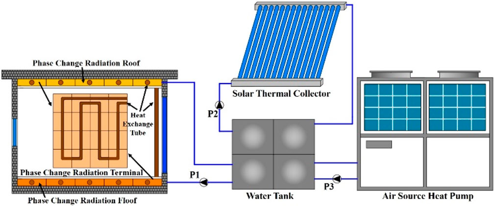
Figure 1 shows the structural schematic diagram of PCRTH system. The bottom and top of a building with a heating area of 1,000 m2 are respectively provided with two PCM maintenance structures with different phase change temperatures. The heat exchange pipe in PCM maintenance structure is linked with the water tank through the circulating water pump P1. The heat generating equipment of PCRTH system adopts the tubular solar collector and the air source heat pump. Moreover, the two heat sources share a water tank. The circulating pump P1 is used to deliver the heat exchange medium to the heat exchange tube. The circulating pump P2 is used to deliver the heat exchange medium to the solar energy collector. The PCRTH system uses the circulating pump P3 to deliver the heat transfer medium to the air source heat pump. The solar energy system and air source heat pump jointly operate to provide heat for buildings in winter, and the PCM maintenance structure can reduce the fluctuation of building room temperature and system energy consumption. The polystyrene board is used as the reference object. Therefore, this paper studies the influence of different maintenance structures on system performance. This study is divided into four structural styles: PCM roof and PCM floor (PCMRF), PCM roof and polystyrene floor (PCMPRF), polystyrene roof and PCM floor (PPCMRF) and polystyrene roof and polystyrene floor (PRF).
3 System research method
3.1 System model structure
3.1.1 Phase change maintenance structure model
The active PCM maintenance structure is a type of radiation terminal that combines capillary tube and PCM. The capillary tube is embedded in the concrete layer as a heat source, and the heat is transferred to PCM in direct contact with the capillary layer in the form of heat conduction to store heat. The PCM layer transfers heat to the surface of the maintenance structure and the room through conduction, radiation and convection respectively. In the process of establishing the active PCM maintenance structure model, ActiveLayer is used in TRNSYS to set capillary diameter, tube spacing, wall thickness and heat conductivity of the tube wall to simulate the thermal performance of the capillary, and finally the heat transfer between the PCM layer is established (Kuznik et al., 2010; Ibáñez et al., 2005).
The heat exchange between a capillary layer and a PCM layer involves direct contact on the boundary surface of different materials, and the main treatment method is generally harmonic average method. Take the heat conduction and heat transfer between control volume P and control volume E (which belong to different materials) as an example. According to the Fourier heat conduction law, the following definition Formula 1 can be obtained:
Further get the Formula 2:
Where qe is the transferred heat flow, W/m2. Te is the interface temperature, oC. TE is the E control the temperature of the volume boundary, oC. TP is the P control the temperature of the volume boundary, oC. λe is the interface equivalent thermal conductivity, W/(m·K). λp is the thermal conductivity of P control the temperature, W/(m·K). λE is the thermal conductivity of E control the temperature, W/(m·K).
The model of the active PCM maintenance structure is mainly assumed as follows.
1) It is assumed that the solid specific heat capacity of the PCM is a constant value.
2) It is assumed that the liquid specific heat capacity of the PCM is a constant value.
3) It is assumed that the contact thermal resistance of energy flow between the PCM layer and the adjacent layer is neglected.
4) It is assumed that the solidification and melting process is carried out at a constant temperature.
When the PCM of the active PCM maintenance structure is completely solid, the temperature Formula 3 at the end is:
When the PCM of the active PCM maintenance structure is completely in liquid phase, the temperature Formula 4 at the end is:
Where Tinitial and Tfinal are the initial temperature and the end temperature of PCM during phase transition, respectively, oC. q1 and q2 are the heat from adjacent walls entering the active PCM maintenance structure, respectively, kJ cps is the solid specific heat capacity of the PCM, kJ/(kg·oC). cpl is the liquid specific heat capacity of the PCM, kJ/(kg·oC). It is assumed that the solid specific heat capacity of PCM is the same as the liquid specific heat capacity of the solid specific heat capacity.
The basic structure of the PCM maintenance structure is shown in Figure 2. The direct contact zone is introduced to simplify the heat transfer process on the direct contact surface between the capillary layer and the PCM layer. TRNSYS can calculate the heat flow internally according to the virtual boundary wall temperature (bottom temperature of the PCM layer) in the direct contact area, so as to convert the heat conduction and heat transfer between the surfaces of the two materials into heat flow output. The thermal mass of the medium in the direct contact zone is very small, and its heat transfer equivalent thermal resistance is neglected, which can be regarded as having no influence on the overall heat transfer process. In the building model, the heat flux on the boundary surface is determined by using the output of the internal surface of the space. The BOUNDARY conditions of the PCM layer are obtained by conversion, and then the boundary temperature is determined using the concept of boundary in TRNSYS. The surface temperature of the PCM layer is fed back to the direct contact area and indoor space to complete the heat transfer process of the whole PCM maintenance structure. The PCM data for roof and floor are shown in Table 1.

Table 1. Parameters of PCM maintenance structure (Kong et al., 2023).
3.1.2 Solar energy system model
The solar energy collector in this study adopted the vacuum tube type. The vacuum tube collector consists of an inner glass tube and an outer glass tube. Table 2 shows the parameters of the solar energy collector model (Gong et al., 2020). The outer surface of the inner tube of the solar collector is coated with a solar radiation absorption coating. The heat transfer fluid flows through the inner tube and is heated. The energy Formulas 5–7 of tubular solar collector is as follows (Gong et al., 2020):
Where Qtotal represents the total heat collected by the tubular solar collector, kJ. Quse represents the transfer heat of tubular solar collector, kJ. Qloss represents the energy loss of vacuum tube solar collector, kJ.
Where L and Dabs represents the length diameter and of tubular solar collector respectively, m. ξabs represents the light absorption efficiency of the inner tube, %. τgla represents the efficiency of sunlight transmission of outer glass tube, %. It represents the total radiation intensity of the sun, W/m2.
Where Tf represents the temperature of heat transfer medium, oC. Ta is the real-time outdoor temperature, oC. εabs represents the light absorption efficiency of inner tube, %. σ represents the Stefan-Boltzmann constant. 0.112 is the heat transfer coefficient in solar collector’s vacuum part.
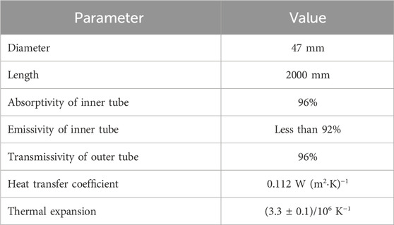
Table 2. Model parameters of vacuum tube solar collector (Gong et al., 2020).
The heat Formula 8 of water tank includes heat gain, heat supply and heat loss. The heat loss of the water tank mainly includes the heat loss at the top, bottom and edge of the water tank (Li et al., 2023).
Where, Cw represents the specific heat capacity of the heat exchange fluid, kJ/(kg·oC). Mw represents the flow rate of heat exchange fluid, kg/h. Tw represents the average temperature inside the water tank, oC. Qin represents the heat gain of the water tank, kJ. Qout represents the heat supply of the water tank, kJ. Atank represents the water tank external surface area, m2.
3.1.3 Air heat pump model
The coefficient of performance (COP) Formula 9 of air source heat pump is as follows (Li et al., 2023):
The heat absorption Formula 10 of outdoor heat exchanger of air source heat pump is as follows:
Where, COP is the coefficient of performance of the Where qH represents the heating capacity, kJ/h. we represents the power consumption, kJ/h. qe represents the heat absorption of evaporator, kJ/h.
The Formulas 11, 12 for calculating the outlet heat exchange fluid temperature of evaporator and condenser of air source heat pump is as follows (Li et al., 2023):
Where, Te, TS,in represents the inlet and outlet heat exchange fluid temperature of the evaporator, respectively, oC. TL,out, TL,in represents the inlet and outlet heat exchange fluid temperature of the condenser, respectively, oC. MS represents the heat medium mass flow of outdoor heat exchanger of air source heat pump kg/h. ML represents the heat medium mass flow of indoor heat exchanger of air source heat pump, kg/h.
3.2 PCRTH system control strategy and research strategy
The circulating pump P1 is controlled according to the room temperature. When the room temperature is not higher than 19oC, the circulating pump P1 is in the running state, and when the room temperature is not lower than 25oC, the circulating pump P1 is in the stopping state. The heat exchange medium in the water tank goes to the floor first and then the roof. The PCRTH system is mainly heated by solar collectors, and the air source heat pump is the auxiliary heating equipment. The water temperature in the water tank is not lower than 50oC. The running state of the circulating pump P2 is affected by the temperature difference between the inlet of the solar collector and the water tank. When the outlet temperature of the solar collector is 5oC higher than the water temperature in the water tank, the circulating pump P2 runs. When the difference between the water temperature of the solar collector and the water temperature in the water tank is 3oC, the circulating pump P2 stops. When the solar collector does not operate due to weather, and the water temperature in the water tank is lower than 50oC, the air source heat pump starts to operate and heat. When the water temperature in the water tank is higher than 55oC, the air source heat pump stops heating.
The cascade phase change radiation terminal heating system combining the solar energy and the air source heat pump was being studied. The roof and floor of the building were designed with PCM maintenance structures with different phase change temperatures. The model of PCRTH system was established and verified based on TRNSYS software, and the comprehensive performance of PCRTH system in different climate zones was explored. The model of PCRTH system is established and verified based on TRNSYS software, and the comprehensive performance of PCRTH system in different climate zones is explored. The research process is shown in Figure 3.
3.3 Hooke-Jeeves optimization process
3.3.1 Hooke-Jeeves optimization principle
Figure 4 shows the GenOpt optimization flow chart. Due to the interaction between system parameters, it is difficult to get the best system parameters to optimize the system performance. GenOpt optimization method can set optimized system parameters to deal with the complexity of system parameter interaction. TrnOpt is a component used to connect TRNSYS and GenOpt. TrnOpt simplifies the optimization problems: selecting optimization variables that affect results, optimization algorithms, and optimization objective functions. In this study, Hooke-Jeeves optimization algorithm called step-by-step acceleration method or pattern search method was selected. The optimization principle of Hooke-Jeeves optimization algorithm can be understood as finding the minimum value of quadratic function to find the lowest point of curve.
3.3.2 Hooke-Jeeves optimization function
The optimization scheme based on the usage of annual fee optimizes the heat collecting area of solar energy system, the hearting power of air source heat pump and the thickness of PCM maintenance structure. The main design parameters of PCRTH system for different urban system simulation models are shown in Table 3. The Heat collecting area of solar energy system is determined accord to that following Formula 13:
Where, Asolar represents the heat collecting area of solar energy system, m2. QH represents the daily heating demand of buildings, MJ. QH is obtained according to the building heat load index and heating area. f represents the solar energy guarantee rate, %. JT represents the annual average daily solar radiation, MJ/(m2d). ηcd represents the thermal efficiency of solar collector, %. ηL represents the heat loss rate, %.
In order to prevent the room temperature from being too low and affecting indoor comfort. The penalty rules defined are as follows:
If the room temperature does not reach 19oC after the heating system is started for 1 h, the punishment will begin. When the room temperature does not reach 19oC, the penalty is 10,000 CNY/h. The penalty will be added to the annual value function of the heating system operating cost. Due to the severity of the penalty, the optimization program will give up selecting system parameters with room temperatures below 19oC. The penalty Formula 14 is as follows:
Where, Ca represents the PCRTH system annual cost, CNY/year. l represents the equipment life, 10 years. Li represents the PCRTH system initial investment, CNY; Co represents the system running cost, CNY/year. The system construction costs of this study include the solar energy collector, water tank, PCM maintenance structure, air source heat pump, circulating pump and polystyrene board. Table 4 shows the cost and service life of each device in the PCRTH system. i is the deposit rate, 5.5%.
3.4 Analytical model
3.4.1 Economic evaluation model
Levelized Cost of Heat (LCOH) is an index to evaluate the economic performance of PCRTH system. The cost of generating one kWh of heat in the whole life cycle of heating system can be expressed by Formula 15 (Huang and Fan, 2019):
Where, Y represents the service life of analyzed heating system, year. y represents the year within the service life of analyzed heating system, year. Cy represents the maintenance cost of analyzed heating system, CNY. CR represents the running cost of analyzed heating system, CNY. Qy represents the heat supply quantity of analyzed heating system, kWh. In this study, the annual maintenance cost was 1% of the system initial investment. The system running cost CR represents mainly came from the power consumption of two circulating pumps and the air source heat pump. d is the discount rate, 3%.
Where, PRP represents the power of circulating pump, kW. PASHP represents the heating power of air source heat pump, kW. Ɵn represents the time-sharing electricity price, CNY/kWh. The peak and valley electricity prices in different cities refer to this reference (Han et al., 2023).
3.4.2 Environmental analysis method
The environmental analysis model mainly focuses on the emission of carbon dioxide (CO2) produced by the PCRTH system. CO2 represents one of the main factors leading to global warming. The calculation Formula 21 of CO2 emission of PCRTH system is as follows (Wei et al., 2020):
Where, Mem represents CO2 pollutant emission, kg/m2. Qd represents the total heat supply of PCRTH system, kWh. LHV is the low calorific value of standard coal, 8.14 kWh/kg. ηe is the power generation efficiency, 0.35. ηnet is the transmission efficiency of the power grid, 0.92. ηeh is thermoelectric conversion efficiency, 0.99. a is the heating area, m2. 2.493 is the conversion coefficient of fuel pollution gas emission.
4 Discussion
4.1 Model validation
According to experiment of the stepped phase-change radiation terminal integrated with a building (Kong et al., 2023), to verify the accuracy of system model. The physical diagram of the experimental setup is shown in Figure 5. Figure 6 shows that the numerical average indoor temperature agrees well with the experimental average indoor temperature during the monitored time. The performance of the model built with TRNSYS is evaluated using the following metrics. xi and yi represent the monitored and simulated values, respectively. xm denotes the mean monitored values. And p is the number points in the test dataset. The mean absolute error (MAE) can be defined as the following Formula 22:
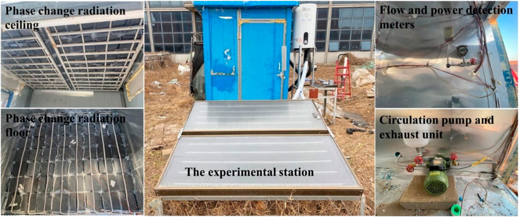
Figure 5. Physical diagram of outdoor real size experimental test room (Kong et al., 2023).
The mean absolute percentage error (MAPE) is introduced to measure the relative error between |xi-yi| and |xi| (i = 1,2, … ,p), and The Formula 23 is as follows:
The MAE and MAPE can quantify the difference between the monitored and simulated indoor temperature. Meanwhile smaller MAE and MAPE values indicate that the model performance is more excellent. It was calculated that MAE and MAPE are 0.3oC and 1.4%, respectively. The results presented that the numerical data agrees well with the experimental data in this study.
4.2 Thermal load analysis of buildings with different maintenance structure
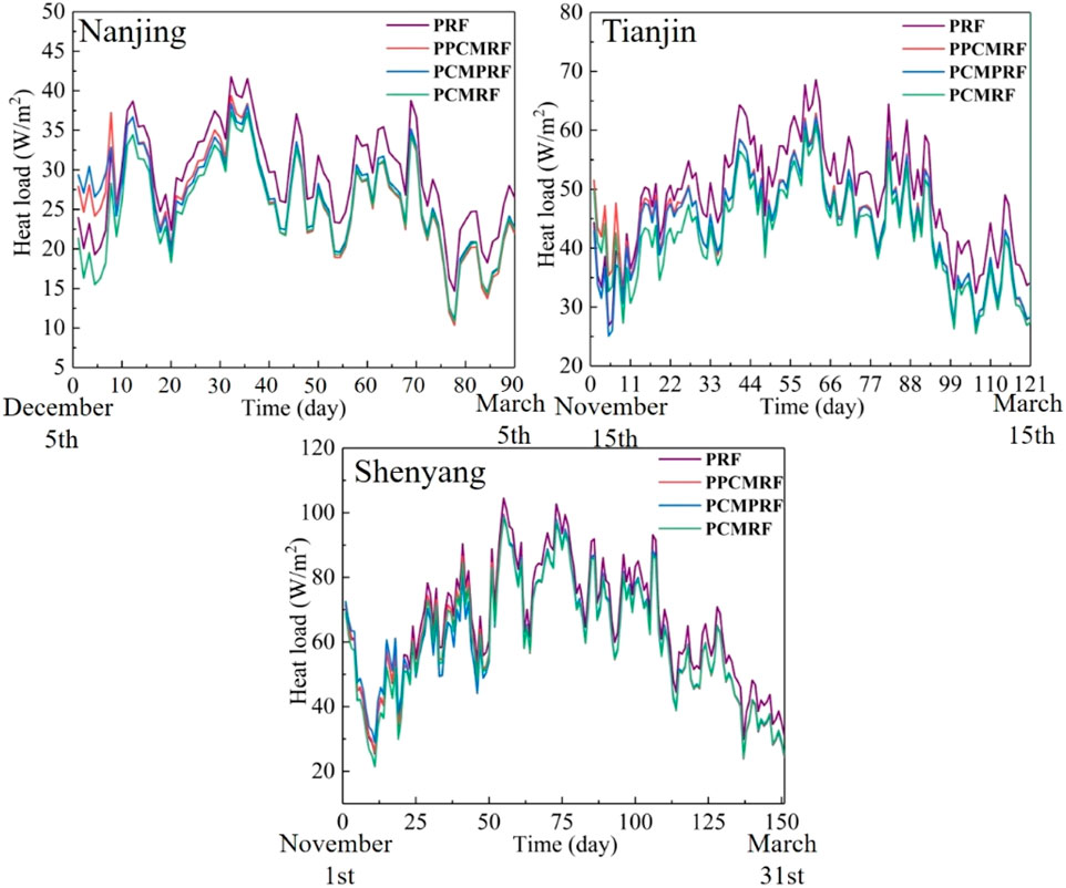
The building heat load of different maintenance structures in three zones are shown in Figure 7. The building heat load in Shenyang was the largest, followed by that in Tianjin and the smallest in Nanjing. This was due to the climatic characteristics of different zones. In the three zones, the building heat load of the PRF structure was the largest, and that of the PCMRF structure was the smallest. The building heat load of PPCMRF structure was similar to that of PCMPRF structure. This was because the PCM maintenance structure effectively improved the thermal inertia of the building maintenance structure and reduced the disturbance of outdoor cold energy to the indoor environment. Meanwhile, PCM maintenance structures can effectively absorb excess indoor heat and avoid heat waste. Through further analysis, it was concluded that the building heat load of PCMRF structure, PPCMRF structure and PCMPRF structure in Nanjing was reduced by 14.0%, 9.9% and 8.8% respectively compared with the PRF structure. The building heat load of PCMRF structure, PPCMRF structure and PCMPRF structure in Tianjin was reduced by 13.2%, 8.8% and 9.4% respectively compared with the PRF structure. The building heat load of PCMRF structure, PPCMRF structure and PCMPRF structure in Shenyang was reduced by 8.1%, 6.8% and 7.1% respectively compared with the PRF structure. This showed that the more PCM maintenance structures were used, the more beneficial it was to reduce the building heat load.
4.3 Room temperature analysis
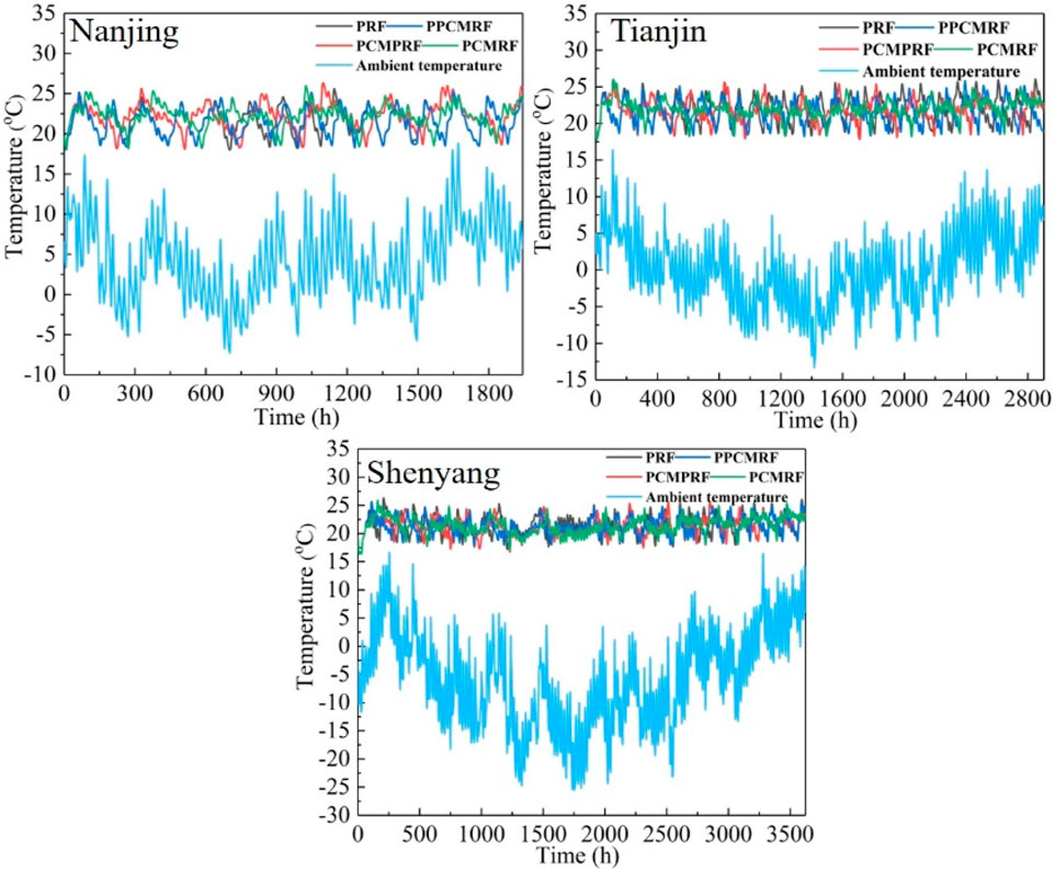
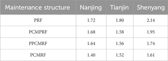
The room temperatures of different maintenance structures in three zones are shown in Figure 8. PCRTH systems met the demands of room heating in three zones, but room temperature fluctuated. This was caused by the start and stop of heating in the PCRTH system. At the same time, the room temperature fluctuations of different maintenance structures were different. Therefore, the standard deviation of room temperature was used as the evaluation index. As shown in Table 5, the room temperature fluctuation of the PCMRF structure in three zones was the smallest, but the room temperature fluctuation of the PRF structure was the largest. This was because the energy storage characteristics of the PCM maintenance structure provided heat for the room when the PCRTH system did not provide heat. Therefore, the reduction in room temperature was delayed. For the single-stage PCM maintenance structure, the room temperature fluctuation of the PPCMRF structure was smaller. This was because the heat of the PPCMRF structure was easier to dissipate into indoor space, while the heat of the PCMPRF structure was easier to transfer to the roof. Therefore, The PCMRF structure was more efficient at reducing room temperature fluctuations and was suitable for three climatic zones.
4.4 Energy consumption analysis
The energy consumption of PCRTH system with different maintenance structures in three zones is shown in Figure 9. Among the three zones, the energy consumption of the PCRTH system based on PCMPRF structure was the smallest, while the energy consumption of the PCRTH system based on PRF structure was the largest. This was due to the high thermal storage density of the PCM maintenance structure. This can store solar energy. Therefore, the PCM maintenance structure was beneficial to reduce the system energy consumption. For the single-stage PCM maintenance structure, the energy consumption of the PCMPRF structure was slightly higher than that of the PPCMRF structure. This was because the heat stored in PCMPRF structure was lost to the roof, which increased the heat supply of PCRTH system. Compared with the PRF structure, the system energy consumption of the PCRTH systems based on PCMPRF structure, PPCMRF structure and PCMRF structure in Nanjing decreased by 2.7%, 4.3% and 6.8% respectively. The energy consumption of the PCRTH systems based on PCMPRF structure, PPCMRF structure and PCMRF structure in Tianjin decreased by 1.2%, 3.3% and 6.8% respectively. The energy consumption of the PCRTH systems based on PCMPRF structure, PPCMRF structure and PCMRF structure in Shenyang decreased by 1.7%, 2.2% and 3.9% respectively. From the point of view of system energy consumption, the PCM maintenance structure had more advantages in the hot summer and cold winter zone. This was due to the large heat load required by buildings in the sever cold zone, and the heat stored in the PCM maintenance structure had little effect on delaying the decrease to room temperature. Therefore, the fluctuation of room temperature of PCMRF structure in Shenyang is the largest.
4.5 System economic analysis
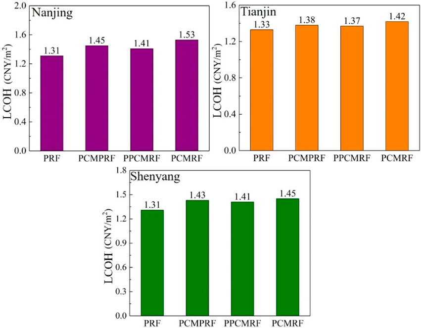
The LCOH values of different maintenance structure system in three zones are shown in Figure 10. The LCOH of the PCRTH system based on PCMRF structure in the three zones was the highest, while that of the PCRTH system based on PRF structure was the lowest. The LCOH of the PCRTH system based on PCMRF structure in Nanjing was 16.8% higher than that of the PCRTH system based on PRF structure. The LCOH of the PCRTH system based on PCMRF structure in Tianjin was 6.8% higher than that of the PCRTH system based on PRF structure. The LCOH of the PCRTH system based on PCMRF structure in Shenyang was 10.7% higher than that of PRF structure. This was due to the high cost of PCM maintenance structure. The lower cost of the polystyrene board led to the lowest construction cost of the PCRTH system based on PRF structure. The LCOH of the PCRTH system based on PCMPRF structure was higher than that of the PPCMRF structure, which was due to the higher system energy consumption of the PCRTH system based on the PCMPRF structure, resulting in higher operating costs. Although the PCM maintenance structure reduced room temperature fluctuation and increased system energy consumption, it caused construction cost to increase. From an economic point of view, the economy of the PCRTH system based on PRF structure in three zones was the best.
4.6 System environment analysis
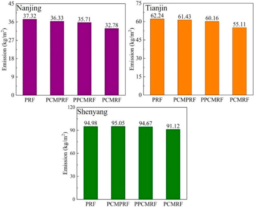
The CO2 emissions of different maintenance structures in three zones are shown in Figure 11. The CO2 emission of the PCRTH system based on PCMRF structure in the three zones was the lowest, while the CO2 emission of the PCRTH system based on PRF structure was the highest. The CO2 emission of the PCRTH system based on PCMPRF structure was slightly higher than that of the PCRTH system based on the PPCMRF structure. At the same time, the CO2 emissions from different maintenance structures in the severe cold zone were the highest in all three zones. Equation (20) showed that the CO2 emission of PCRTH system was affected by the system energy consumption. Therefore, the greater the energy consumption of the system, the higher the CO2 emissions from the system.
4.7 Analysis of influence of PCM maintenance structure thickness on system performance
In order to further analyze the influence of PCM maintenance structure on the performance of PCRTH system. First, the effect of PCM maintenance structures with different thicknesses on system energy consumption was analyzed. Taking PCMRF structure as an example, the influence of thickness of PCM maintenance structure on system energy consumption in three zones are shown in Figure 12. The energy consumption of PCRTH system in the three zones decreased with the increase in the thickness of the PCM maintenance structure. The reason was that the thickening of the PCM maintenance structure will store heat in the building maintenance structure. Therefore, the PCM maintenance structure can store more solar energy, and helped to reduce the building heat load. Through further analysis, it can be known that with the increase in the thickness of the PCM maintenance structure, the energy consumption of PCRTH systems in hot summer and cold winter zone, the cold zone and the severe cold zone decreased by 24.2%,23.1% and 16.7% respectively, compared with the PCM maintenance structure with a thickness of 0.01m.
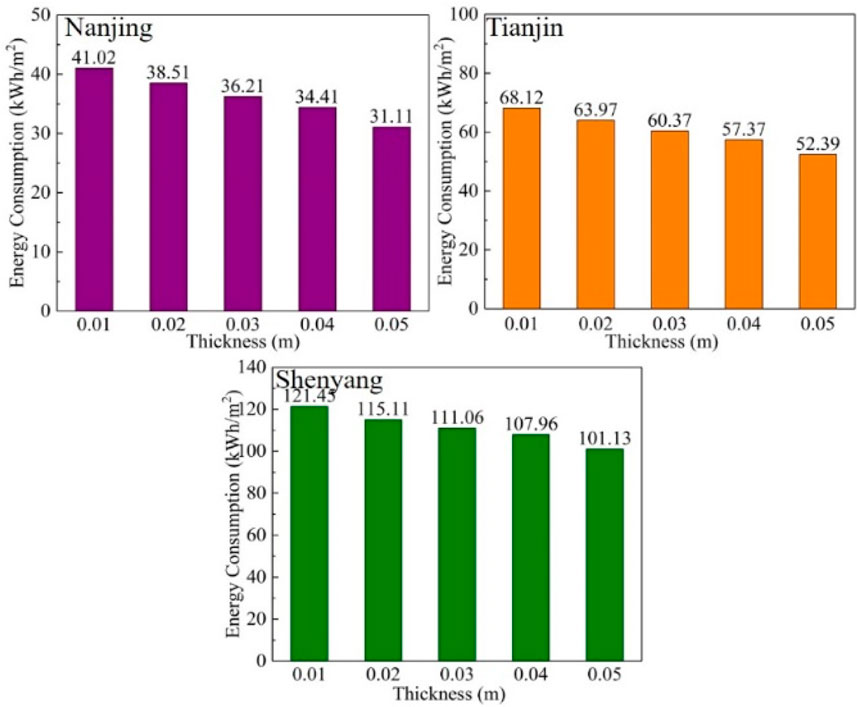
Figure 12. Influence of thickness of PCM plate on system energy consumption corresponding to different cities.
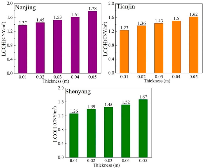
The influence of thickness of PCM maintenance structure on system LCOH in three zones are shown in Figure 13. The influence of the increase in the thickness of the PCM maintenance structure on the LCOH of PCRTH system was opposite to that of the energy consumption. The LCOH of the PCRTH system decreased with the increase in the thickness of the PCM maintenance structure. Through further analysis, it can be known that with the increase in the thickness of the PCM maintenance structure, the LCOH of PCRTH systems in Nanjing, Tianjin and Shenyang increased by 29.9%, 31.7% and 32.5% respectively, compared with the PCM maintenance structure with a thickness of 0.01 m.
4.8 Hooke-Jeeves optimization analysis
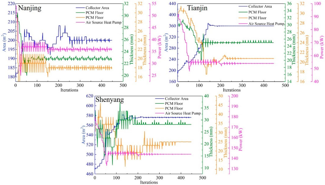
From the above analysis, it can be seen that room temperature fluctuation of the PCMRF structure was the smallest. At the same time, the PCRTH system based on PCMRF structure had low energy consumption and remarkable environmental benefits, but the heating cost of the system was high. Therefore, the heat collecting area of solar energy system, the heating power of air source heat pump, PCM roof thickness and PCM floor thickness in the PCMRF structure system were taken as optimization parameters. As shown in Figure 14, the fluctuation of each optimization parameter tended to be stable after 400 iterations. Therefore, the Hooke-Jeeves optimization method was feasible in the optimization calculation of the PCRTH system.
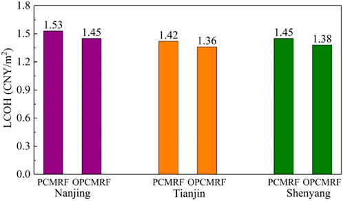
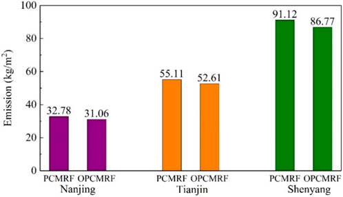
The optimization results are shown in Table 6. As shown in Figure 15, the energy consumption of the optimized PCRTH system in three zones had been reduced. The energy consumption of Nanjing, Tianjin and Shenyang decreased by 10.7%, 9.3% and 9.7% respectively. This was due to the increase in solar heat collection area in the PCRTH system in the three zones. Therefore, the heat supply quantity of the solar energy system was improved and the power consumption of the air source heat pump was reduced. As shown in Figure 16, the LCOH of the optimized PCRTH system in these three zones had been reduced. LCOH of PCRTH systems in Nanjing, Tianjin and Shenyang decreased by 5.2%,4.2% and4.8% respectively. This was because the construction cost of PCM maintenance structures and air heat pumps had been reduced. The cost of PCM maintenance structures in Nanjing, Tianjin and Shenyang decreased by 33.3%, 25.0% and 11.7% respectively. Although the increase in solar heat collection capacity led to a slight increase in construction costs, the decrease in system energy consumption reduced the operating cost of the system. As shown in Figure 17, the CO2 emissions of the PCRTH system in the three zones all decreased. CO2 emissions from PCRTH systems in Nanjing, Tianjin and Shenyang decreased by 5.2%, 4.5% and 4.8% respectively.
5 Conclusion
In this study, the influences of PCM maintenance structure on room temperature fluctuations, system energy consumption, system heating cost, and CO2 emissions in different heating zones were analyzed. The thickness of PCM maintenance structure, the heat collecting area of solar energy system, and the heating power of air source heat pump in different zones are optimized by Hooke-Jeeves optimization method. It provided guidance for the application of heating system based on PCM maintenance structure in different zones. The conclusions of the study are as follows:
Because the PCM maintenance structure improved the heat storage capacity of the building maintenance structure and stored the excess indoor heat, the PCMRF maintenance structure was the most beneficial to reduce the building heat load and reduced the fluctuation of room temperatures during the winter. The PCMRF maintenances structure in Nanjing, Tianjin and Shenyang reduced the heat load of buildings by 14.0%, 13.2% and 8.1%, respectively.
Because the PCM maintenance structure can store solar energy, the energy consumption and pollutant emissions of the system based on PCM maintenance structures in the three zones were lower than those of the system based on polystyrene board. However, the LCOH of systems based on PCM maintenance structure in Nanjing, Tianjin and Shenyang is 16.8%, 6.7% and 10.7% higher than that based on polystyrene board, respectively.
The increase of the thickness of PCM maintenance structure was beneficial to reduce the energy consumption of the PCRTH system, but the heating cost of the PCRTH system was submitted. The LCOH of PCRTH systems in Nanjing, Tianjin and Shenyang decreased by 5.2%, 4.2% and 4.8% respectively based on the Hooke-Jeeves optimization method.
Data availability statement
The original contributions presented in the study are included in the article/supplementary material, further inquiries can be directed to the corresponding author.
Author contributions
ZZ: Writing–review and editing, Writing–original draft. XY: Writing–original draft, Writing–review and editing. JL: Writing–original draft, Writing–review and editing. LW: Writing–review and editing, Writing–original draft. BJ: Writing–review and editing, Writing–original draft. GN: Writing–original draft, Writing–review and editing. ZY: Writing–review and editing, Writing–original draft. CL: Writing–review and editing, Writing–original draft.
Funding
The author(s) declare that financial support was received for the research, authorship, and/or publication of this article. This work was supported by the Natural Science Foundation of Hebei Province, China (Grant No. E2020202147) and Science and Technology Project of Inner Mongolia Electric Economy and Technology Academy (Project No. 2023-5-37).
Acknowledgments
Thanks to the support of by the Natural Science Foundation of Hebei Province, China (Grant No. E2020202147) and Science and Technology Project of Inner Mongolia Electric Economy and Technology Academy (Project No. 2023-5-37). Thanks to all the authors of this article for their contributions in this article.
Conflict of interest
The authors declare that the research was conducted in the absence of any commercial or financial relationships that could be construed as a potential conflict of interest.
Generative AI statement
The author(s) declare that no Generative AI was used in the creation of this manuscript.
Publisher’s note
All claims expressed in this article are solely those of the authors and do not necessarily represent those of their affiliated organizations, or those of the publisher, the editors and the reviewers. Any product that may be evaluated in this article, or claim that may be made by its manufacturer, is not guaranteed or endorsed by the publisher.
References
Ahmed, A., Ge, T., Peng, J., W, T. B., and You, S. (2022). Assessment of the renewable energy generation towards net-zero energy buildings: a review. Energy Build. 256, 111755. doi:10.1016/j.enbuild.2021.111755
Belfiori, E., and Rezai, A. (2024). Implicit carbon prices: making do with the taxes we have. J. Environ. Econ. Manage. 125, 102950. doi:10.1016/j.jeem.2024.102950
Cai, R., Sun, Z., Wang, E., Meng, E., Wang, J., and Dai, M. (2021). Review on optimization of phase change parameters in phase change material building envelopes. J. Build. Eng. 35, 101979. doi:10.1016/j.jobe.2020.101979
Canelli, R., Fontana, G., and Realfonzo, R. (2024). Energy crisis, economic growth and public finance in Italy. Energy Econ. 132, 107430. doi:10.1016/j.eneco.2024.107430
Chen, L., Yang, H., Xiao, Y., Tang, P., Liu, S., Chang, M., et al. (2024). Exploring spatial pattern optimization path of urban building carbon emission based on low-carbon cities analytical framework: a case study of Xi'an, China. Sustain. Cities Soc. 111, 105551. doi:10.1016/j.scs.2024.105551
Christopher, S., Parham, K., Saidur, R., Farid, M., Ma, Z., Thakur, A. K., et al. (2021). A critical review on phase change material energy storage systems with cascaded configurations. J. Clean. Prod. 283, 124653. doi:10.1016/j.jclepro.2020.124653
Diaconu, B., Cruceru, M., and Anghelescu, L. (2023). A critical review on heat transfer enhancement techniques in latent heat storage systems based on phase change materials. Passive and active techniques, system designs and optimization. J. Build. Eng. 61, 106830. doi:10.1016/j.est.2023.106830
Du, Z., Liu, G., Huang, X., He, Y., and Yang, X. (2023). Numerical studies on a fin-foam composite structure towards improving melting phase change. Int. J. Heat. Mass Transf. 208, 124076. doi:10.1016/j.ijheatmasstransfer.2023.124076
Faraj, K., Khaled, M., Faraj, J., Hachem, F., and Castelain, C. (2021). A review on phase change materials for thermal energy storage in buildings: heating and hybrid applications. J. Build. Eng. 33, 101913. doi:10.1016/j.est.2020.101913
Gong, J., Jiang, Z., Luo, X., Du, B., Wang, J., and Lund, P. (2020). Straight-through all-glass evacuated tube solar collector for low and medium temperature applications. Sol. Energy 201, 935–943. doi:10.1016/j.solener.2020.03.069
Han, J., Zhang, C., Wang, L., Chang, Z., Zhao, Q., Shi, Y., et al. (2023). Research on operation optimization of heating system based on electric storage coupled solar energy and air source heat pump. Energy Eng. 120 (9), 1991–2011. doi:10.32604/ee.2023.029749
Hiris, D. P. O., Balan, C., and Balan, M. C. (2022). Preliminary sizing of solar district heating systems with seasonal water thermal storage. Heliyon 8 (2), e08932. doi:10.1016/j.heliyon.2022.e08932
Huang, J., Fan, J., and Kong, W. (2019). Economic analysis and optimization of household solar heating technologies and systems. Energy Technol. Assess. 36, 100532. doi:10.1016/j.seta.2019.100532
Ibáñez, M., Lázaro, A., Zalba, B., and Cabeza, L. (2005). An approach to the simulation of PCMs in building applications using TRNSYS. Appl. Therm. Eng. 25 (11-12), 1796–1807. doi:10.1016/j.applthermaleng.2004.11.001
Karschin, I., and Geldermann, J. (2015). Efficient cogeneration and district heating systems in bioenergy villages: an optimization approach. J. Clean. Prod. 104, 305–314. doi:10.1016/j.jclepro.2015.03.086
Khan, I., Chowdhury, H., Rasjidin, R., Alam, F., Islam, T., and Islam, S. (2012). Review of wind energy utilization in south asia. Procedia Eng. 49, 213–220. doi:10.1016/j.proeng.2012.10.130
Kishore, R., Booten, C., Bianchi, M., Vidal, J., and Jackson, R. (2022). Evaluating cascaded and tunable phase change materials for enhanced thermal energy storage utilization and effectiveness in building envelopes. Energy Build. 260, 111937. doi:10.1016/j.enbuild.2022.111937
Kong, X., Jiang, L., Guo, L., Wang, N., and Ren, J. (2023). Experimental study on the performance of a stepped phase-change radiation terminal integrated with a building used in summer and winter. J. Energy Storage 62, 106860. doi:10.1016/j.est.2023.106860
Kong, X., Wang, L., Li, H., Yuan, G., and Yao, C. (2020). Experimental study on a novel hybrid system of active composite PCM wall and solar thermal system for clean heating supply in winter. Sol. Energy 195, 259–270. doi:10.1016/j.solener.2019.11.081
Kuznik, F., Virgone, J., and Johannes, K. (2010). Development and validation of a new TRNSYS type for the simulation of external building walls containing PCM. Energy Build. 42 (7), 1004–1009. doi:10.1016/j.enbuild.2010.01.012
Larwa, B., Cesari, S., and Bottarelli, M. (2021). Study on thermal performance of a PCM enhanced hydronic radiant floor heating system. Energy 225, 120245. doi:10.1016/j.energy.2021.120245
Lawag, R., and Ali, H. (2022). Phase change materials for thermal management and energy storage: a review. J. Build. Eng. 55, 105602. doi:10.1016/j.est.2022.105602
Li, D., Zhuang, B., and Wang, X. (2022). Incorporation technology of bio-based phase change materials for building envelope: a review. Energy Build. 260, 11920. doi:10.1016/j.enbuild.2022.111920
Li, J., and Huang, J. (2020). The expansion of China's solar energy: challenges and policy options. Renew. Sustain. Energy Rev. 132, 110002. doi:10.1016/j.rser.2020.110002
Li, J., Wei, S., Dong, Y., Liu., X, , and Novakovic, V. (2023). Technical and economic performance study on winter heating system of air source heat pump assisted solar evacuated tube water heater. Appl. Therm. Eng. 221, 119851. doi:10.1016/j.applthermaleng.2022.119851
Ma, X., Wang, M., Lan, J., Li, C., and Zou, L. (2022). Influencing factors and paths of direct carbon emissions from the energy consumption of rural residents in central China determined using a questionnaire survey. Adv. Clim. Change Res. 13 (5), 759–767. doi:10.1016/j.accre.2022.06.008
Maturo, A., Vallianos, C., Buonomano, A., and Athienitis, A. (2023). A novel multi-level predictive management strategy to optimize phase-change energy storage and building-integrated renewable technologies operation under dynamic tariffs. Energ. Convers. Manag. 291, 117220. doi:10.1016/j.enconman.2023.117220
Mughal, N., Arif, A., Jain, V., Chupradit, S., Shabbir, M. S., Ramos-Meza, C. S., et al. (2022). The role of technological innovation in environmental pollution, energy consumption and sustainable economic growth: evidence from South Asian economies. Energy Strategy Rev. 39, 100745. doi:10.1016/j.esr.2021.100745
Panchal, J., Modi, K., and Patel, V. (2022). Development in multiple-phase change materials cascaded low-grade thermal energy storage applications: a review. Clean. Eng. Technol. 8, 100465. doi:10.1016/j.clet.2022.100465
Ralegaonkar, R., and Gupta, R. (2010). Review of intelligent building construction: a passive solar architecture approach. Renew. Sust. Energy Rev. 14 (8), 2238–2242. doi:10.1016/j.rser.2010.04.016
Rathore, P., Gupta, N., Yadav, D., Shukla, S. K., and Kaul, S. (2022). Thermal performance of the building envelope integrated with phase change material for thermal energy storage: an updated review. Sust. Cities Soc. 79, 103690. doi:10.1016/j.scs.2022.103690
Sharma, R., Ganesan, P., Tyagi, V., and Sandaran, S. (2015). Developments in organic solid–liquid phase change materials and their applications in thermal energy storage. Energy Convers. Manag. 95, 193–228. doi:10.1016/j.enconman.2015.01.084
Shen, Y., Liu, S., Jin, H., Rehman Mazhar, A., Zhang, S., Chen, T., et al. (2024). Thermal investigation and parametric analysis of cascaded latent heat storage system enhanced by porous media. Appl. Therm. Eng. 238, 121982. doi:10.1016/j.applthermaleng.2023.121982
Singh, A., Kumar, A., Akshayveer, O., and Singh, O. (2021). Effect of integrating high flow naturally driven dual solar air heaters with Trombe wall. Energy Convers. Manag. 249, 114861. doi:10.1016/j.enconman.2021.114861
Wang, L., Guo, L., Ren, J., and Kong, X. (2022). Using of heat thermal storage of PCM and solar energy for distributed clean building heating: a multi-level scale-up research. Appl. Energy 321, 119345. doi:10.1016/j.apenergy.2022.119345
Wang, L., Kong, X., Ren, J., Fan, M., and Li, H. (2022). Novel hybrid composite phase change materials with high thermal performance based on aluminium nitride and nanocapsules. Energy 238, 121775. doi:10.1016/j.energy.2021.121775
Wang, X., Li, W., Luo, Z., Wang, K., and Shah, S. (2022). A critical review on phase change materials (PCM) for sustainable and energy efficient building: design, characteristic, performance and application. Energy Build. 260, 111923. doi:10.1016/j.enbuild.2022.111923
Wei, W., Ni, L., Yao, C., and Yang, Y. (2020). Performance analysis of a quasi-two stage compression air source heat pump in severe cold zone with a new control strategy. Appl. Therm. Eng. 174, 115317. doi:10.1016/j.applthermaleng.2020.115317
Wei, X., Shi, X., Li, Y., Ma, H., Ban, S., Liu, X., et al. (2024). Analysis of the European energy crisis and its implications for the development of strategic energy storage in China. J. Energy Storage 82, 110522. doi:10.1016/j.est.2024.110522
Zhang, J., Li, Y., Li, L., Liu, X., Zhang, W., Tang, C., et al. (2024). An integrated system combining MDBHE (multi-casing DBHE) and heat pump achieves heating and cooling for medium-deep geothermal energy utilization. Energy 295, 131061. doi:10.1016/j.energy.2024.131061
Zhao, L., Zhang, H., and Mbachu, J. (2023). Multi-sensor data fusion for 3D reconstruction of complex structures: a case study on a real high formwork project. Remote Sens. 15 (5), 1264. doi:10.3390/rs15051264
Keywords: phase change material, solar energy, building maintenance structure, clean heating, optimization algorithm
Citation: Zhang Z, Yu X, Li J, Wang L, Jin B, Niu G, Yang Z and Li C (2024) Explore the operational performance of phase change radiation terminal heating system in different heating zones of China. Front. Energy Res. 12:1504788. doi: 10.3389/fenrg.2024.1504788
Received: 01 October 2024; Accepted: 22 November 2024;
Published: 09 December 2024.
Edited by:
Minzhang Liu, Tianjin Chengjian University, ChinaReviewed by:
Mingyao Yao, Tianjin University, ChinaChenxiao Zheng, Tianjin University of Commerce, China
Kun Yang, Yanshan University, China
Copyright © 2024 Zhang, Yu, Li, Wang, Jin, Niu, Yang and Li. This is an open-access article distributed under the terms of the Creative Commons Attribution License (CC BY). The use, distribution or reproduction in other forums is permitted, provided the original author(s) and the copyright owner(s) are credited and that the original publication in this journal is cited, in accordance with accepted academic practice. No use, distribution or reproduction is permitted which does not comply with these terms.
*Correspondence: Lu Wang, d2xsMTIxMGhlYnV0QDE2My5jb20=
 Zhen Zhang1
 Lu Wang