- Three Gorges Hydropower Plant, China Yangtze Power Co., Ltd., Yichang, China
In power systems, potential transformers (PTs) are responsible for stepping down high voltage to low voltage. However, a short circuit between turns on the primary side of a generator outlet PT can significantly reduce the secondary phase voltage, leading to voltage imbalances and generating fundamental zero-sequence voltage. This situation is analogous to a stator winding ground fault, often resulting in incorrect protective operations. To prevent such malfunctions, this paper analyzes the causes of false tripping through simulation and proposes a fault diagnosis model based on the Circular Sparrow Search Algorithm (CSSA)-optimized Gaussian Mixture Model (GMM), referred to as the CSSA-GMM model. A fault simulation model was established using Simulink to verify the differences between turn-to-turn short circuits and stator ground faults, and their electrical characteristics were studied. The results indicate that under different fault types, parameters such as the three-phase primary current and three-phase secondary voltage exhibit varying relationships and fault variations. By optimizing the GMM parameters using CSSA and comprehensively analyzing the voltage and current characteristics, this model can effectively diagnose turn-to-turn short circuit faults at various short-turn ratios, achieving an accuracy rate of up to 98%. This approach clearly distinguishes PT turn-to-turn short circuits from generator outlet stator ground faults, providing new insights for fault recognition and supporting the intelligent development of relay protection systems.
1 Introduction
Potential transformers (PTs) are critical components in power systems, responsible for converting high transmission voltages into the lower voltages required by relays and measuring equipment (Mejia-Barron et al., 2017). Due to the direct connection of the PT’s primary side to high-voltage systems, they must adhere to stringent insulation performance standards. Factors such as uneven voltage distribution across the windings, inadequate maintenance, and environmental influences like lightning and humidity can significantly increase the risk of PT failure. These conditions may subject the transformer to mechanical, electrical, or thermal stress, potentially leading to insulation breakdown (Sun et al., 2019). This concern is particularly acute at the generator output, where such failures could result in severe power outages (Lei et al., 2014). Currently, traditional methods for addressing inter-turn short circuits in PT windings, such as lightning impulse testing and partial discharge techniques, have limitations. These include complex modulation setups and poor resistance to electromagnetic interference (Portugues et al., 2008). Additionally, for transformers with high turn ratios, issues like transformer ratio measurements and winding DC resistance measurements are not immediately apparent. The application of frequency response analysis is also challenging due to its limited scope and difficulty in implementation (Sun et al., 2021).
When a ground fault occurs in the stator winding of a generator, the fundamental zero-sequence stator protection, established using voltage data measured through the PT at the generator outlet, can effectively safeguard against significant accidents (Jaafari et al., 2017). However, if an inter-turn short circuit fault occurs on the primary side of the PT at the outlet, the equivalent impedance of that phase relative to ground decreases, while the impedances of the other two phases remain unchanged. This imbalance in the stator’s three-phase ground impedance can result in specific zero-sequence voltages at the machine terminal and the neutral point, potentially triggering the fundamental zero-sequence voltage ground protection (Davarpanah et al., 2016). Therefore, it is crucial to analyze the mechanism by which inter-turn short circuits in the PT’s primary winding lead to the activation of stator ground protection in order to develop a universal diagnostic method that prevents erroneous protection activations.
Since the structure of PT is similar to that of conventional transformers, diagnostic methods developed for inter-turn short circuit faults in transformers can be adapted for PT. González et al. analyzed the effects of load, fault location, fault severity, and load power factor on transformer performance. Their results indicated that, under unbalanced conditions, comparisons of phase currents can effectively identify the presence of internal transformer faults (González et al., 2004). Meira et al. proposed a strategy for detecting inter-turn short circuits in transformers by monitoring electrical variables and utilizing differential admittance to derive diagnostic indicators (Meira et al., 2024). Additionally, Ballal et al. demonstrated that continuous monitoring of the primary side voltage, current, and load patterns enables early detection of inter-turn faults (Ballal et al., 2015). By analyzing electrical quantities during both faulted and normal operating conditions, effective diagnostics for inter-turn faults can be achieved.
In recent years, there has been an increasing emphasis on inter-turn short circuit faults in PTs, with numerous researchers exploring detection methods specifically tailored for these faults. Nie et al. were the first to identify the characteristic parameters of the high-voltage winding in dry-type voltage transformers, investigating how these parameters vary with frequency under both fault and non-fault conditions. Based on these characteristics, they utilized a pulse voltage method to detect inter-turn short circuit faults in dry-type voltage transformers (Nie et al., 2023). Li et al. introduced two innovative sensitivity methods for identifying inter-turn faults in voltage transformers during operation, concentrating on the excitation current and the phase difference between the primary voltage and excitation current. Their findings revealed that the severity of inter-turn faults is positively correlated with excitation current and negatively correlated with phase difference (Li and Guo, 2022). Their research emphasizes the importance of waveform characteristics following inter-turn short circuits during PT operation for effective fault diagnosis. Zhang et al. proposed a knowledge-assisted online detection method that significantly improves the fault detection efficiency of capacitive PTs (Zhang et al., 2024). Liu et al. combined traditional approaches with modern technology, employing hybrid algorithms to diagnose inter-turn short circuit faults in PTs (Liu et al., 2021). Therefore, for inter-turn short circuit faults in PTs at the generator outlet and stator ground faults in the generator, it is essential to combine traditional fault analysis methods with modern intelligent technologies for effective fault diagnosis.
Artificial intelligence techniques, such as neural networks (Sun et al., 2021; Yang et al., 2023) and deep learning (Wang et al., 2019), have demonstrated significant potential in the field of fault diagnosis due to their robust data analysis capabilities, which are particularly well-suited to the complexities of power system faults (Liang et al., 2023). Zhang et al. combined Variational Mode Decomposition (VMD) with Convolutional Neural Networks (CNN) to accurately identify fault locations and types in a small current grounding source system model for relay protection dynamic simulation (Zhang et al., 2022). Hu et al. proposed a novel fault diagnosis framework based on deep learning that incorporates anti-interference capabilities, enabling the online extraction of key fault features from the complex operational data of power systems and the assessment of fault conditions and types (Xu et al., 2023). The Gaussian Mixture Model (GMM) has emerged as a promising method for fault classification, with numerous studies employing GMM techniques for fault diagnosis and identification (Yan et al., 2017). Ribeiro Junior et al. utilized a combination of GMM and Mahalanobis distance to achieve high accuracy in identifying motor faults (Ribeiro et al., 2023). Maliuk et al. enhanced classification performance for bearing fault diagnosis using GMM (Maliuk et al., 2021). The GMM holds considerable promise in the fields of fault diagnosis and classification.
This paper first analyzes the fault characteristics of inter-turn short circuits on the primary side of PT at the generator outlet, conducting an equivalent circuit analysis to understand the causes of stator ground protection activation. Building upon this analysis, a model for inter-turn short circuits and stator ground faults is developed using MATLAB and Simulink to obtain relevant electrical quantities. The voltage and current characteristics obtained from the simulations serve as training parameters to construct a PT fault diagnosis model based on GMM, which is further optimized using the Sparrow Search Algorithm (SSA) to achieve high diagnostic accuracy. This method relies solely on the electrical parameters of the circuit and can operate under live conditions. It can be applied for the detection of PT inter-turn short circuits, thereby preventing erroneous activations of stator ground protection.
2 Analysis of inter-turn short circuit in primary winding of generator outlet PT
Currently, the stator ground protection system for large generator units is typically set up using both fundamental zero-sequence voltage protection and third harmonic protection. This combination ensures comprehensive 100% coverage for stator ground faults. The fundamental zero-sequence voltage stator ground protection effectively addresses approximately 90% of single-phase ground faults occurring in the stator windings, from the machine terminal to within the machine itself (Zielichowski and Fulczyk, 2003). In contrast, the third harmonic stator ground protection accounts for about 20% of single-phase ground faults in the stator windings, extending from the generator’s neutral point into the machine (Friedemann et al., 2020; Zhu Y et al., 2018). This configuration compensates for the protection of the dead zone associated with the fundamental zero-sequence voltage near the neutral point (Safari-Shad and Franklin, 2015).
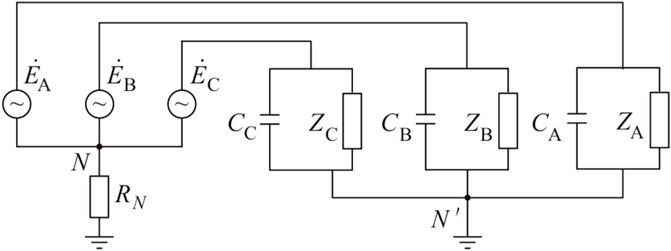
From the perspective of the fundamental zero-sequence voltage stator ground protection system, its coverage includes the generator stator windings and the busbar area. This area extends from the generator terminal to both the main transformer and the plant transformer. Any ground faults occurring within this area will activate the stator ground protection (Barkas et al., 2024). This section presents a fault characteristic analysis based on an event in which the stator ground protection was triggered, resulting in the tripping of a generator due to an insulation fault in the voltage transformer at the generator terminal. The equivalent circuit of the voltage transformer at the generator terminal is illustrated in Figure 1.
In Figure 1, CA, CB and CC represent the equivalent capacitance of each phase of the generator voltage system to ground, and RN represents the low-resistance value of the generator neutral point.
where YA, YB, and YC represent the admittance of phases A, B, and C to ground at the generator terminal, respectively. Under normal operating conditions, the admittances of the three phases to ground are approximately equal, at which point the neutral point voltage
Assuming under normal conditions that the equivalent capacitance to ground for all three phases is equal, denoted as C, and the secondary load impedance of the PT is equal for all phases, denoted as z, with the PT’s voltage transformation ratio being NT. When an inter-turn short circuit occurs on phase A of the PT primary side, let the short-circuit turn ratio be α (0 < α ≤ 100%). In this case, the voltage transformation ratio for phase A becomes
By substituting Equation 2 into Equation 1, the following can be obtained:
According to the national guidelines for PT selection and calculation, let the rated output capacity of the generator outlet PT be Sn, with a rated phase voltage of 57.74 V on the secondary side. The secondary load is calculated as k (25%–100%) times the rated output capacity, with a power factor of 0.8 lagging. The secondary load impedance of the PT is then:
In order to limit the dynamic overvoltage to no more than 2.6 times the rated phase voltage, it is required that RN ≤ 1/3ωC. Therefore, it is set as Equation 5:
By substituting Equations 4, 5 into Equation 3, it becomes possible to solve for
where, A, B, and ρ are all greater than zero. At this point, the phase-to-ground voltages for all three phases can be solved, as shown in Equation 7:
Based on Equation 7, the modulus of the phase-to-ground voltages for all three phases can be solved. It can be observed that when an inter-turn short circuit occurs on phase A, the phase-to-ground voltage of phase C is the highest. Additionally,
Similarly, the phase-to-ground voltage expressions for a short circuit in phases B and C can be derived. By solving and comparing their modulus values, it is determined that when a short circuit occurs in phase B, the voltage of phase A increases, and when a short circuit occurs in phase C, the voltage of phase B increases. Based on this analysis, the following pattern can be observed: when an inter-turn short circuit occurs in the primary winding of the generator outlet PT, the phase immediately following the one with the highest voltage is the faulted phase. This behavior is analogous to the fault characteristics observed when the stator is grounded through a transition resistor. Additionally, due to the voltage imbalance among the three phases, the zero-sequence voltage obtained from the PT’s secondary-side voltage data collection will exceed the threshold set for fundamental zero-sequence voltage stator protection, resulting in a false trip.
3 Simulation modeling analysis of PT inter-turn short circuit and stator grounding
The analysis of the equivalent model for the PT inter-turn short circuit at generator outlets has identified the causes of erroneous stator grounding protection. However, it is still unclear how to effectively distinguish between the two types of faults. This highlights the need for further investigation into their characteristics. Creating simulation models to analyze these fault characteristics at different stages is essential for improving fault diagnosis methods. Numerous researchers have explored the causes of electrical equipment faults through modeling (Noda et al., 2016; Maliuk et al., 2021). In this study, we employed widely used electrical simulation software, MATLAB and Simulink, to create circuit models for both fault types. We captured the variations in electrical parameters at the moment of fault occurrence, validated this numerical analysis, and obtained additional fault characteristics. This work lays the groundwork for future fault diagnosis efforts.
As shown in Figure 2, a circuit model was developed to analyze a stator winding single-phase ground fault and an inter-turn short circuit fault at the primary side of the PT at the outlet, all within the same generator structure. The single-phase PT fault is represented as a three-winding transformer with a short circuit occurring in one of the phases. Following the design in Figure 2, the simulation model was finalized, as depicted in Figure 3. The three-phase generator was simulated by configuring three single-phase voltage sources with different phases, each having a voltage level of 6060 V. The stator winding impedance Z was set to (100 + j0.001) Ω, and the three-phase capacitance to ground was set at 0.5 × 10⁻⁶ F to facilitate numerical simulation design.
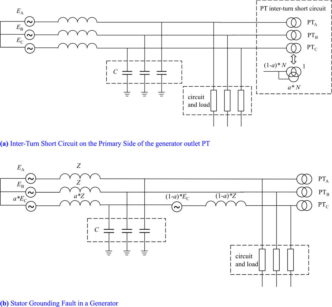
Figure 2. Model schematic for generator stator winding and outlet PT fault. (A) Inter-Turn Short Circuit on the Primary Side of the generator outlet PT. (B) Stator Grounding Fault in a Generator.
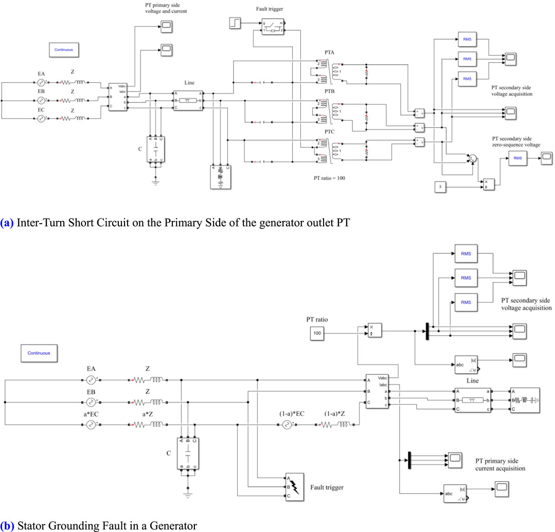
Figure 3. Establishment of the simulation model for generator stator winding and outlet PT fault. (A) Inter-Turn Short Circuit on the Primary Side of the generator outlet PT. (B) Stator Grounding Fault in a Generator.
In Figure 3A, three three-winding transformers are utilized to illustrate the internal structure of the PT at the generator outlet. The PT is classified as a capacitive voltage transformer with a transformation ratio of 100:1. When a fault occurs, a controllable switch is used to short-circuit the selected winding proportion, enabling us to capture the changes in electrical parameters at the moment of the fault. The short-circuit turn ratio is configured through the transformer module. The parameter design process for the stator grounding fault simulation model is analogous, with a denoting the proportion of the single-phase grounding fault in the stator winding.
The simulation calculation is set to 0.5 s, with the fault occurring at the 0.1-s mark. By collecting and comparing the characteristics of the electrical parameters, we validate that PT faults may lead to erroneous stator grounding protection and investigate the variations in other electrical parameters.
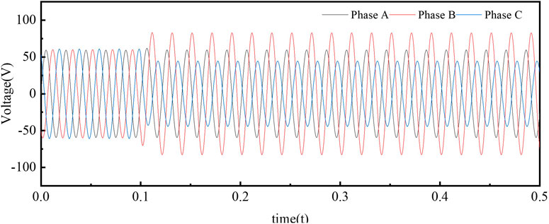
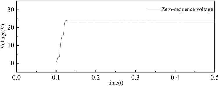
When a 1% inter-turn short circuit occurs in the C-phase winding of the primary side of the PT, the resulting three-phase secondary voltages and the zero-sequence voltage are illustrated in Figures 4, 5. It can be observed that during the fault in the C phase, the B-phase voltage reaches its peak value of 72.59 V, exceeding the normal voltage magnitude of 57.82 V. In contrast, the voltage in the faulted C phase drops to a minimum of 42.25 V, while the A-phase voltage measures 46.78 V, which is slightly higher than that of the C phase but still below the normal voltage level.
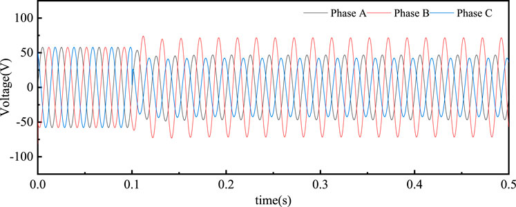
Figure 4. Three-phase voltage on the secondary side during inter-turn short circuit on the primary side of PT.
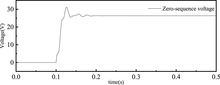
Figure 5. Zero-sequence voltage on the secondary side during inter-turn short circuit on the primary side of PT.
As a result of this voltage imbalance, the zero-sequence voltage significantly increases after the fault, reaching 26 V. This observation confirms that when an inter-turn short circuit fault occurs in one phase of the PT’s primary side, the phase with the highest voltage corresponds to the adjacent faulted phase.
When a fault occurs in the generator stator winding, existing methods typically utilize a combination of zero-sequence fundamental frequency voltage protection and third harmonic voltage protection to detect and diagnose stator winding faults. The operational principle of the fundamental zero-sequence voltage stator grounding protection is based on the idea that even with a high-resistance grounding transition, the resulting voltage imbalance will still generate a fundamental zero-sequence voltage when a grounding fault occurs in the generator winding (Tai and Juergen, 2006). As illustrated in Figures 6, 7, when a grounding fault with high transition resistance occurs near the generator neutral point, the three-phase voltage and fundamental zero-sequence voltage waveforms on the secondary side of the PT can be observed. In this scenario, when the C phase experiences a fault, the B phase voltage rises to a peak of 82.85 V, exceeding the normal voltage magnitude of 58.76 V. Conversely, the voltage in the faulted C phase drops to a minimum of 44.24 V, while the A phase voltage measures 49.48 V, slightly higher than that of the C phase and close to the normal voltage level.
Due to this voltage imbalance, the zero-sequence voltage significantly increases after the fault occurs, reaching a level of 23 V. This observation indicates that the electrical characteristics during an inter-turn short circuit fault in the primary winding of the PT at the generator outlet are similar to those observed during a fault in the generator stator winding. Specifically, when a fault occurs in one phase, the voltage magnitude of the preceding phase on the secondary side of the PT increases noticeably, while the voltage of the faulted phase decreases significantly. This results in a marked increase in the zero-sequence voltage on the secondary side, ultimately triggering the fundamental zero-sequence voltage stator grounding protection.
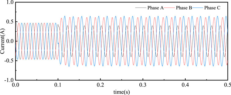
Measurements of voltage indicate that when a fault occurs, the characteristics observed on the secondary side of the PT during a primary winding inter-turn short circuit are similar to those seen during a generator stator ground fault. Therefore, it is crucial to introduce new fault characteristics to differentiate between these two types of faults. Using a simulation model, we obtained the three-phase current waveforms on the primary side of the PT under various fault conditions, as illustrated in Figures 8, 9. In the case of an inter-turn short circuit in the PT, when the C phase experiences a short circuit, the impedance of that phase decreases. As a result, with equal voltage across the generator’s three phases, the primary current of the C phase significantly increases to 0.631 A, the highest among the three phases, surpassing the normal operating current. Conversely, during a stator ground fault, the relationships among the three-phase currents reflect those of the secondary side voltages. When a single-phase ground fault occurs in the C phase winding, the current value remains lower than the normal operating current, despite the high impedance of the transition resistance.
This analysis indicates that variations in primary current occur during different types of faults. However, the factors influencing primary current are numerous, and fluctuations may arise during actual diagnostics due to changes in system load and the generator’s power factor. Therefore, identifying the generator outlet PT inter-turn faults and stator ground faults requires a comprehensive consideration of their electrical characteristics, which prompts the development of new fault diagnosis methods.
4 Diagnosis of generator outlet PT primary side inter-turn short circuit fault using CSSA-GMM model
To address the erroneous activation of stator ground protection resulting from inter-turn short circuit faults on the primary side of the PT at the generator outlet, this study conducts a numerical analysis of the underlying mechanisms using equivalent circuit calculations. Additionally, it replicates similar fault scenarios through simulation modeling. This approach allows for the investigation of the overall fault characteristics of both fault types and the reasons for misjudgment. In recent years, artificial intelligence algorithms, such as neural networks and machine learning, have been widely employed in the fault diagnosis and analysis of electrical equipment (Qiu et al., 2023; Wang et al., 2023). These methods offer new insights and ways to improve the efficiency and accuracy of fault detection. Researchers have utilized various artificial intelligence techniques, including CNN, Long Short-Term Memory (LSTM) models, and Deep Belief Networks, to diagnose faults in power equipment, such as transformers and generators (Xu et al., 2023; Ning and Pei, 2024). GMM is widely utilized for describing mixed density distributions, representing a combination of multiple Gaussian distributions (Etienam et al., 2024). In the context of machine learning classification problems, GMM effectively captures the distribution characteristics of data within classes in the feature space. This capability highlights its significant potential in the field of fault classification and diagnosis. Therefore, this study develops a GMM-based fault diagnosis model for the generator outlet, utilizing the fault mechanisms and characteristics identified in the previous sections. The diagnosis logic aligns with real-world conditions.
GMM is statistical models used to describe multiple Gaussian distributions within a dataset. They assume that data points are generated from a combination of different Gaussian components, which together form a complex probability distribution (Guan et al., 2024). Each Gaussian component is defined by its mean, covariance, and mixing weight, with the weight indicating the significance of that component within the overall model. The probability density function of a GMM can be expressed as follows:
where K represents the number of components, and
Training a GMM typically employs the Expectation-Maximization (EM) algorithm, which consists of two key steps: In the Expectation step, the posterior probability that each data point belongs to each component is calculated, as follows:
In the Maximization step, based on these posterior probabilities, the model parameters are updated. The new mixing weights, means, and covariances are updated as follows:
where Nk represents the total weight of the kth component. This iterative process continues until the model parameters converge.
In diagnosing inter-turn short-circuit faults in generator outlet PTs using the GMM method, a comprehensive analysis of voltage and current characteristics is conducted. After initializing the feature quantities, the GMM is constructed, and the probability density function is modeled. This study focuses on seven primary fault types: inter-turn short-circuit faults on the primary side of three-phase PTs at generator outlet, ground faults in three-phase generator stator windings, and normal operating conditions. The fault diagnosis system is designed to accommodate various voltage levels and accurately diagnose different degrees of fault severity.
To facilitate the accurate identification of faults across multiple voltage levels and varying short-circuit ratios, a simulation model generated a total of 411 datasets corresponding to different fault categories. These datasets comprise nine features: the effective values of three-phase voltage on the secondary side of the PT, effective values of three-phase current on the primary side of the PT, the effective values of the fundamental zero-sequence voltage on the secondary side of the PT, the transformation ratio of the PT, and the voltage level. After shuffling the data, the datasets were divided into training, validation, and test sets in an 8:1:1 ratio for model training. To enhance the accuracy of the model, two hidden layers were established, each containing 32 neurons. Figure 10 illustrates the training process and results of the model utilizing only the GMM approach.
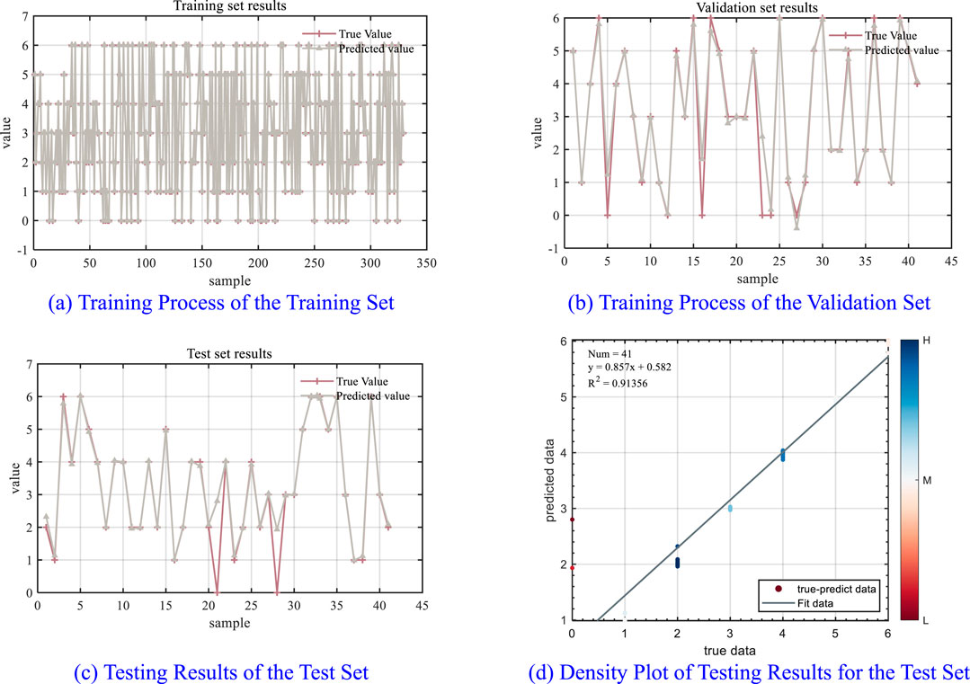
Figure 10. Training process and testing results of the GMM fault diagnosis model. (A) Training process of the training set. (B) Training process of the validation set. (C) Testing results of the test set. (D) Density plot of testing results for the test set.
As illustrated in Figure 10, the GMM model demonstrates a high degree of fit during both the training and validation phases; however, there remains potential for improvement in diagnostic accuracy during testing. This limitation can be attributed to factors such as the relatively small size of the training dataset and the high dimensionality of the features. Figure 10D indicates that the model’s accuracy is 83.055%. Therefore, it is essential to optimize the model. After establishing the GMM, appropriate optimization algorithms should be employed to address the unknown parameters within the model, thereby enhancing its accuracy.
Swarm Intelligence Optimization is a stochastic optimization algorithm that shows the behavior of natural populations (Demirdelen et al., 2022). This approach is less sensitive to initial conditions and demonstrates strong adaptability, making it widely applicable in various parameter optimization scenarios. The SSA is an emerging swarm intelligence optimization technique that mimics the cooperative and competitive behaviors of sparrows during foraging (Li and Jia, 2022). The core concept of the SSA is to facilitate cooperation and exploration within the search space through two distinct roles: scouts and followers. Key steps in the algorithm include initializing the positions and velocities of the sparrows, followed by evaluating their fitness based on the objective function. Scouts update their positions during the search process using the following formula:
where Xi represents the position of the ith sparrow, Xb denotes the position of the currently optimal sparrow, Xj refers to the positions of surrounding sparrows, and r1 and r2 are random numbers.
In each iteration, scouts search for better solutions by updating their positions, while followers replicate the actions of the scouts. Through continuous iterations, the sparrow population gradually converges toward the optimal solution, ultimately achieving global optimization. This algorithm has demonstrated strong performance in function optimization, engineering design, and other complex problems. Compared to the Grey Wolf Optimization (GWO) algorithm (Guan et al., 2024) and the Particle Swarm Optimization (PSO) algorithm (Wang et al., 2023), the SSA algorithm exhibits greater stability and higher optimization accuracy. However, as it is still in the developmental stage, it has certain limitations. Specifically, the algorithm employs random initialization of the population without prior knowledge, which can result in uneven distributions of the initial population. To address this issue, a circular chaotic mapping approach is utilized to initialize a more stable and uniformly distributed sparrow population. By employing the CSSA, the established GMM is effectively solved, resulting in the CSSA-GMM fault diagnosis model. The model training results are presented in Figure 11.
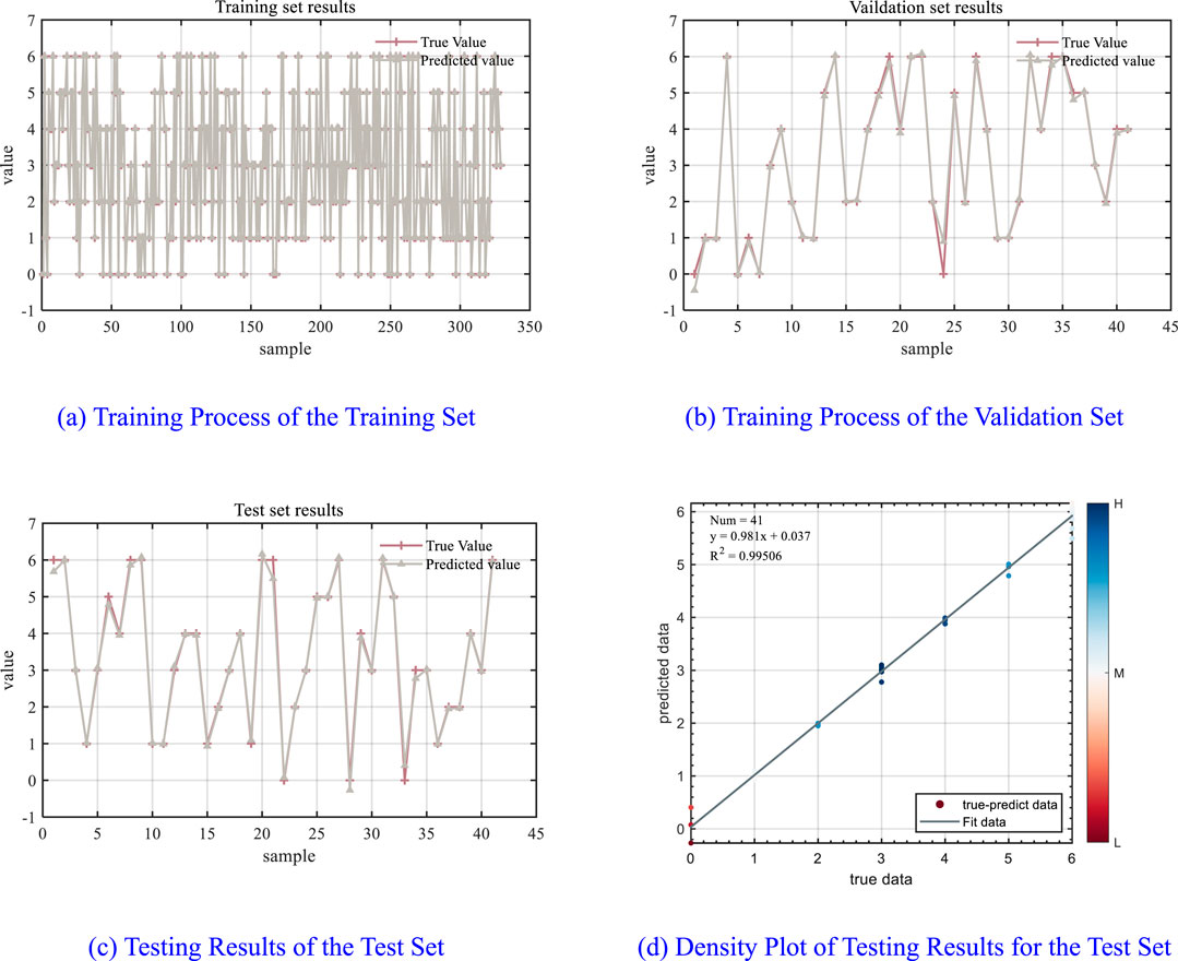
Figure 11. Training process and testing results of the CSSA-GMM fault diagnosis model. (A) Training process of the training set. (B) Training process of the validation set. (C) Testing results of the test set. (D) Density plot of testing results for the test set.
Figure 11 illustrates that the CSSA-GMM model proposed in this study demonstrates superior performance in diagnosing and distinguishing between inter-turn short-circuit faults and stator ground faults in generator outlet PTs, achieving an accuracy of 99.478%. In the actual detection process, there are errors in data collection; therefore, when establishing a fault diagnosis model, it is necessary to consider that the data may contain noise. This paper re-obtained 40 sets of data through simulation and processed the original measurement data by adding Gaussian white noise (Yang et al., 2016). The already trained GMM-CSSA model was then tested. Although its accuracy decreased, it remained above 95%, indicating that the model has a certain level of robustness and reliability. To further validate the effectiveness of this method, diagnostic tests were conducted using other artificial intelligence algorithms, with the training results presented in Table 1. In comparison, the method introduced in this paper significantly enhances fault diagnosis accuracy, consistently maintaining a high level of precision across various voltage levels and effectively identifying different degrees of fault severity.

Table 1. Different Artificial Intelligence Techniques for Identifying Inter-Turn Short-Circuit Faults in generator outlet PT.
5 Summary and prospects
PTs play a crucial role in power systems by converting high transmission voltages into lower voltages that are suitable for relays and measuring devices. However, when an inter-turn short-circuit fault occurs on the primary side of the PT at the generator outlet, the voltage of the faulted phase on the secondary side significantly decreases, while the voltage on the preceding phase markedly increases. This voltage imbalance leads to the emergence of fundamental zero-sequence voltage, a characteristic similar to that observed in stator winding ground faults of generators. Such similarities can often result in the misoperation of zero-sequence voltage protection, leading to unnecessary losses. To prevent these misoperations and develop novel fault diagnosis methods, this paper begins with an equivalent circuit analysis of inter-turn short-circuit faults on the primary side of the generator outlet PT. Numerical calculations are utilized to elucidate the causes of misoperation. A simulation model for both PT inter-turn short-circuit faults and generator stator winding ground faults is established using Simulink, which validates the numerical analysis through simulations. This model demonstrates the distinctions between inter-turn short-circuit faults and stator ground faults, and it investigates their electrical characteristics.
The electrical characteristics of these two fault types are similar, exhibiting only subtle differences. Therefore, it is essential to integrate both voltage and current features for effective fault diagnosis. To ensure that the electrical characteristics are adaptable across various voltage levels and can accurately identify faults under different severity conditions, this study combines neural network technology with electrical analysis. We propose a CSSA-GMM neural network diagnostic model that employs the CSSA to determine the unknown parameters in the GMM, thereby enhancing model accuracy. This method effectively diagnoses both PT inter-turn short-circuit faults and stator ground faults, achieving an accuracy of 99.466% across various voltage levels and different short-circuit ratios. Despite the influence of noise, the accuracy remains at 96.478%. The model presented in this study offers a reliable approach for diagnosing and distinguishing PT inter-turn short-circuit faults at generator outlets, which are often misidentified at the generator outlet. This advancement contributes to the intelligent fault recognition capabilities of relay protection systems.
Data availability statement
The original contributions presented in the study are included in the article/supplementary material, further inquiries can be directed to the corresponding author.
Author contributions
YW: Conceptualization, Data curation, Formal Analysis, Funding acquisition, Investigation, Methodology, Project administration, Software, Writing–original draft, Writing–review and editing. CL: Data curation, Formal Analysis, Methodology, Resources, Software, Supervision, Writing–original draft, Writing–review and editing. YA: Funding acquisition, Investigation, Methodology, Project administration, Resources, Software, Visualization, Writing–review and editing. HS: Funding acquisition, Investigation, Methodology, Software, Validation, Writing–review and editing. SZ: Funding acquisition, Investigation, Methodology, Resources, Software, Writing–review and editing. YS: Funding acquisition, Methodology, Project administration, Resources, Visualization, Writing–review and editing.
Funding
The author(s) declare that financial support was received for the research, authorship, and/or publication of this article. This achievement is funded by China Yangtze Power Co., Ltd. (Research Project Contract No: Z212302034). The funder was not involved in the study design, collection, analysis, interpretation of data, the writing of this article, or the decision to submit it for publication.
Conflict of interest
Authors YW, CL, YA, HS, SZ, and YS were employed by China Yangtze Power Co., Ltd.
Generative AI statement
The author(s) declare that no Generative AI was used in the creation of this manuscript.
Publisher’s note
All claims expressed in this article are solely those of the authors and do not necessarily represent those of their affiliated organizations, or those of the publisher, the editors and the reviewers. Any product that may be evaluated in this article, or claim that may be made by its manufacturer, is not guaranteed or endorsed by the publisher.
References
Ballal, M., Suryawanshi, H., Mishra, M., and Chaudhari, B. (2015). Interturn faults detection of transformers by diagnosis of neutral current. IEEE Trans. Power Deliv. 31 (3), 1096–1105. doi:10.1109/TPWRD.2015.2461433
Barkas, D., Katemliadis, S., Tarousinof, G., Kalkanis, K., and Psomopoulos, C. (2024). Failure causes and operational life of measuring transformers installed in 150 kV and 400 kV transmission network. Electr. Power Syst. Res. 231, 110341. doi:10.1016/j.epsr.2024.110341
Davarpanah, M., Keravand, M., Faiz, J., Mousa-Haddadi, A., Morsali, H., Mahmoudi, A., et al. (2016). Precise locating of stator winding earth fault in large synchronous generators. IEEE Trans. Ind. Appl. 53 (3), 3137–3145. doi:10.1109/TIA.2016.2616397
Demirdelen, T., Esenboga, B., Aksu, I. O., Ozdogan, A., Yavuzdeger, A., Ekinci, F., et al. (2022). Modeling and experimental validation of dry-type transformers with multiobjective swarm intelligence-based optimization algorithms for industrial application. Neural comput. Appl. 34 (2), 1079–1098. doi:10.1007/s00521-021-06447-z
Etienam, C., Law, K. J., Wade, S., and Zankin, V. (2024). Fast deep mixtures of Gaussian process experts. Mach. Learn. 113 (3), 1483–1508. doi:10.1007/s10994-023-06491-x
Friedemann, D., Motter, D., and Oliveira, R. (2020). Stator-ground fault location method based on third-harmonic measures in high-impedance grounded generators. IEEE Trans. Power Deliv. 36 (2), 794–802. doi:10.1109/TPWRD.2020.2993219
González, G. D., Fernández, J. G.-A., and Arboleya, P. A. (2004). Diagnosis of a turn-to-turn short circuit in power transformers by means of zero sequence current analysis. Electr. Power Syst. Res. 69 (2-3), 321–329. doi:10.1016/j.epsr.2003.07.014
Guan, S., Wu, T., and Yang, H. (2024a). Research on transformer fault diagnosis method based on ACGAN and CGWO-LSSVM. Sci. Rep. 14 (1), 17676. doi:10.1038/s41598-024-68141-z
Guan, Y., He, S., Ren, S., Liu, S., and Li, D. (2024b). Mixture Gaussian process model with Gaussian mixture distribution for big data. Chemom. Intell. Lab. 253, 105201. doi:10.1016/j.chemolab.2024.105201
Jaafari, K., Negahdari, A., Toliyat, H., Nader, S., and Russ, F. (2017). Modeling and experimental verification of a 100% stator ground fault protection based on adaptive third-harmonic differential voltage scheme for synchronous generators. IEEE Trans. Ind. Appl. 53 (4), 3379–3386. doi:10.1109/TIA.2017.2682165
Lei, X., Li, J., Wang, Y., Mi, S., and Xiang, C. (2014). Simulative and experimental investigation of transfer function of inter-turn faults in transformer windings. Electr. Power Syst. Res. 107, 1–8. doi:10.1016/j.epsr.2013.08.021
Li, B., and Jia, S. (2022). Research on diagnosis method of series arc fault of three-phase load based on SSA-ELM. Sci. Rep. 12 (1), 592. doi:10.1038/s41598-021-04605-w
Li, P., and Guo, P. (2022). Diagnosis of interturn faults of voltage transformer using excitation current and phase difference. Eng. Fail. Anal. 134, 105979. doi:10.1016/j.engfailanal.2021.105979
Liang, Y., He, A., Yuan, J., Wu, T., and Jiao, Z. (2023). An accurate fault location method for distribution lines based on data fusion of outcomes from multiple algorithms. Int. J. Electr. Power Energy Syst. 153, 109290. doi:10.1016/j.ijepes.2023.109290
Liu, C., Muda, W., and Kuo, C. (2021). Turn-to-turn fault diagnosis on three-phase power transformer using hybrid detection algorithm. Appl. Sci. 11 (6), 2608. doi:10.3390/app11062608
Maliuk, A., Prosvirin, A., Ahmad, Z., Kim, C., and Kim, J. (2021). Novel bearing fault diagnosis using Gaussian mixture model-based fault band selection. Sensors 21 (19), 6579. doi:10.3390/s21196579
Meira, M., Bossio, G., Ruschetti, C., and Verucchi, C. (2024). Inter-turn short-circuit detection through differential admittance monitoring in transformers. IEEE Trans. Instrum. Meas. 73, 3519508. doi:10.1109/TIM.2024.3390202
Mejia-Barron, A., Valtierra-Rodriguez, M., Granados-Lieberman, D., Olivares-Galvan, J., and Escarela-Perez, R. (2017). Experimental data-based transient-stationary current model for inter-turn fault diagnostics in a transformer. Electr. Power Syst. Res. 152, 306–315. doi:10.1016/j.epsr.2017.07.020
Nie, H., Wang, H., Wang, W., and Yao, Y. (2023). Detection of interturn short-circuit faults in dry-type voltage transformers using the pulse voltage method. Energies 16 (19), 6883. doi:10.3390/en16196883
Ning, L., and Pei, D. (2024). Power line fault diagnosis based on convolutional neural networks. Heliyon 10 (8), e29021. doi:10.1016/j.heliyon.2024.e29021
Noda, T., Takizawa, H., and Nakajima, T. (2016). A study of electromagnetic transient simulations using IEEJ's West-10 benchmark power system model. Electr. Power Syst. Res. 138, 195–201. doi:10.1016/j.epsr.2016.03.028
Portugues, I., Moore, P., Glover, I., Johnstone, C., Mckosky, R., Goff, M., et al. (2008). RF-based partial discharge early warning system for air-insulated substations. IEEE Trans. Power Deliv. 24 (1), 20–29. doi:10.1109/TPWRD.2008.2005464
Qiu, Z., Li, W., Tang, T., Wang, D., and Wang, Q. (2023). Denoising graph neural network based hydraulic component fault diagnosis method. Mech. Syst. Sig. Process. 204, 110828. doi:10.1016/j.ymssp.2023.110828
Ribeiro, R., De Almeida, F., Jorge, A., Pereira, J., Francisco, M., and Gomes, G. (2023). On the use of the Gaussian mixture model and the Mahalanobis distance for fault diagnosis in dynamic components of electric motors. J. Braz. Soc. Mech. Sci. Eng. 45 (3), 139. doi:10.1007/s40430-023-04056-6
Safari-Shad, N., and Franklin, R. (2015). Adaptive 100% stator ground fault protection based on third-harmonic differential voltage scheme. IEEE Trans. Power Deliv. 31 (4), 1429–1436. doi:10.1109/TPWRD.2015.2494843
Sun, J., Yang, Q., Su, P., Wu, S., Chen, S., and He, L. (2019). Diagnosis of winding fault in three-winding transformer using lightning impulse voltage. Electr. Power Syst. Res. 175, 105898. doi:10.1016/j.epsr.2019.105898
Sun, Y., Wu, W., Sun, Y., Song, X., and Wu, H. (2021). Research on signal injection method with high frequency for distribution network capacitive current measurement. Electr. Power Syst. Res. 195, 107135. doi:10.1016/j.epsr.2021.107135
Tai, N., and Juergen, S. (2006). Differential protection based on zero-sequence voltages for generator stator ground fault. IEEE Trans. Power Deliv. 22 (1), 116–121. doi:10.1109/TPWRD.2006.887099
Wang, L., Yang, F., Xu, F., Wang, Z., Li, J., and Yao, W. (2023). A novel error-correcting Particle swarm optimization back propagation Fault Diagnosis method for microgrid. Electronics 12 (13), 2855. doi:10.3390/electronics12132855
Wang, Y., Liu, M., Bao, Z., and Zhang, S. (2019). Stacked sparse autoencoder with PCA and SVM for data-based line trip fault diagnosis in power systems. Neural comput. Appl. 31, 6719–6731. doi:10.1007/s00521-018-3490-5
Xu, B., Li, H., Liu, Y., Zhou, F., and Yan, B. (2023). Fault diagnosis in asynchronous motors based on an optimal deep bidirectional long short-term memory networks. Meas. Sci. Technol. 34 (12), 125909. doi:10.1088/1361-6501/acf681
Yan, H., Zhou, J., and Pang, C. (2017). Gaussian mixture model using semisupervised learning for probabilistic fault diagnosis under new data categories. IEEE Trans. Instrum. Meas. 66 (4), 723–733. doi:10.1109/TIM.2017.2654552
Yang, Y., Tu, F., Huang, S., Tu, Y., and Liu, T. (2023). Research on CNN-LSTM DC power system fault diagnosis and differential protection strategy based on reinforcement learning. Front. Energy Res. 11, 1258549. doi:10.3389/fenrg.2023.1258549
Yang, Z., Liu, Y., Zhu, X., Chen, X., and Zhang, J. (2016). Removing forecasting errors with white Gaussian noise after square root transformation. J. Forecast. 35 (8), 741–750. doi:10.1002/for.2407
Zhang, C., Guo, P., Cheng, C., Cheng, C., Pan, L., and Li, H. (2024). Detecting breakdowns in capacitor voltage transformers: a knowledge-assisted online approach. Measurement 226, 114197. doi:10.1016/j.measurement.2024.114197
Zhang, Q., Ma, W., Li, G., Ding, J., and Xie, M. (2022). Fault diagnosis of power grid based on variational mode decomposition and convolutional neural network. Electr. Power Syst. Res. 208, 107871. doi:10.1016/j.epsr.2022.107871
Zhu, Y., Li, Y., Sang, J., Bao, M., and Zang, H. (2018). Analysis and improvement of adaptive coefficient third harmonic voltage differential stator grounding protection. Energies 11 (6), 1430. doi:10.3390/en11061430
Keywords: power transformer, inter-turn short circuit fault, stator ground fault, Gaussian mixture model, circular sparrow search algorithm potential transformer, circular sparrow search algorithm
Citation: Wei Y, Li C, Ai Y, Shen H, Zeng S and Sun Y (2024) Analysis of primary side turn-to-turn short circuit fault in PT at the generator outlet and diagnosis using CSSA-GMM. Front. Energy Res. 12:1504706. doi: 10.3389/fenrg.2024.1504706
Received: 01 October 2024; Accepted: 31 October 2024;
Published: 21 November 2024.
Edited by:
Hui Wan, University of Colorado Colorado Springs, United StatesReviewed by:
Yixing Ding, Nanjing Tech University, ChinaZhengshi Chang, Xi’an Jiaotong University, China
Copyright © 2024 Wei, Li, Ai, Shen, Zeng and Sun. This is an open-access article distributed under the terms of the Creative Commons Attribution License (CC BY). The use, distribution or reproduction in other forums is permitted, provided the original author(s) and the copyright owner(s) are credited and that the original publication in this journal is cited, in accordance with accepted academic practice. No use, distribution or reproduction is permitted which does not comply with these terms.
*Correspondence: Yang Wei, WWFuZ1dlaUREMTFAcHJvdG9ubWFpbC5jb20=
 Yang Wei*
 Chen Li