- 1State Grid Sichuan Electric Power Research Institute, Chengdu, China
- 2Power Internet of Things Key Laboratory of Sichuan Province, Chengdu, China
To improve the stability margin of the power grid under unconventional conditions and enhance the fault emergency support capability of AC/DC grids, this paper investigates multi-resource and multi-objective collaboration damping control strategy method based on a multi-input multi-output (MIMO) system model, which considers the multiple control impacts. Based on the analysis of system oscillation characteristics, appropriate feedback signals and controller installation locations are selected based on the modal ratio index. to realize the control effect, the HVDC and energy storage devices are used. Finally, the coupled robust controllers based on robust mechanism are designed out. Simulation results in PSCAD software show that, compared to traditional damping controllers, the controller designed is more suitable for system conditions with large perturbations and uncertainties.
1 Introduction
Actively and steadily promoting carbon peaking and carbon neutrality (“dual carbon”) goals, and accelerating the construction of a safe, stable, economically efficient, coordinated supply and demand, flexible, and intelligent new power system to ensure energy supply and energy security is the mission of China’s energy and power industry development (Sheta et al., 2023). As the project with the largest investment and engineering volume in China’s western development strategy, the implementation of the “West-to-East Electricity Transmission” project has effectively alleviated environmental pollution and energy shortages in China’s southeast coastal areas. It is the right choice to achieve optimal allocation and efficient utilization of energy resources in China (Jiang et al., 2022).
Ultra-high voltage AC transmission technology has advantages such as strong networking capabilities, long transmission distances, and flexible landing points. It can connect adjacent provincial power grids, achieving time and seasonal complementarity, mutual support among wind, photovoltaic, hydro, and thermal power generation, as well as cross-regional and cross-basin compensation and adjustment (Li Q. et al., 2024). Ultra-high voltage DC transmission technology, with its advantages of low transmission loss, large transmission capacity, point-to-point transmission, strong controllability, and no stability issues (Tao et al., 2020), has increasingly become the mainstay of the “West-to-East Electricity Transmission” project.
Taking the East China Power Grid as an example, it has developed into a typical AC-DC hybrid power grid structure with multiple UHV DC feed-ins and UHV AC interconnections, as shown in Figure 11. As of April 2024, there are 13 UHV DC transmission projects feeding into the East China Power Grid, with a total rated power of 78.8 million kilowatts, and the DC landing points are very dense. The UHV AC main grid structure in East China is based on the “Wandian Dongsong” project, forming a UHV AC loop network. The East China UHV AC-DC hybrid power grid has played a significant role in ensuring national energy security, promoting the achievement of the “dual carbon” goals, and facilitating the integration of renewable energy (Jiang et al., 2023a).
However, while the large-scale access of UHV AC and DC achieves energy mutual assistance and adequate power supply, it also brings many challenges to the operation and control of the large power grid. The flexible controllability of High Voltage Direct Current (HVDC) transmission has fundamentally changed the dynamic characteristics of the AC-DC hybrid power grid compared to traditional power systems (Wen et al., 2023).
The main manifestations are the continuous increase in power from outside the region and the continuous replacement of local conventional power sources by the development of renewable energy. This has led to a decreasing proportion of traditional power generation units being operational, resulting in characteristics such as low system inertia and a high degree of “hollowness” (Verma et al., 2023). Consequently, this brings about the issue of reduced oscillation damping ratios in the near-field of DC landing points, further increasing the risk of low-frequency oscillations in the power grid. As there are often multiple oscillation modes among units, the existing damping controller design methods are mostly in the form of single-input single-output (SISO) (Abd El-Kareem et al., 2021). Single-control-loop damping controllers do not reflect the interactive effects between multiple control loops, which can weaken or even worsen the effect of closed-loop control in complex power systems or when there are long time delays in wide-area signals.
In response to the aforementioned issues of low-frequency oscillation analysis and suppression, scholars at home and abroad have conducted extensive and in-depth research at various levels, including “source-grid-load-storage”. At the power source level, installing a power system stabilizer (PSS) (Zou et al., 2024), but PSS will be invalid if interzone modes occurs. At the load level, power output can be adjusted by regulating the load, thereby achieving system power balance. At the energy storage level, by coordinating with renewable energy devices, the power injected into the system can be changed to compensate for the randomness of renewable energy output. At the grid level, additional damping control based on renewable energy converters, HVDC, and FACTS has been a research hotspot. Additional damping control has a faster response speed and better suppression effect, and it is still applicable to sub/super-synchronous oscillations in power systems with large-scale renewable energy access. Its principle is to extract signals related to damping characteristics from the AC system as feedback signals, use them as inputs to the damping controller, and add the signals output by the transfer function to a certain control channel of the converter equipment, which can enhance the system damping (Wilches-Bernal et al., 2019). In 2007, China Southern Power Grid developed the world’s first multi-loop DC adaptive coordinated control system based on wide-area information. This system utilizes the Wide-Area Measurement System (WAMS) of China Southern Power Grid, together with the GaoZhao and XingAn DC systems, to build a closed-loop control system, which can effectively suppress oscillations between Yunnan-Guangdong and Yunnan-Guizhou regions (Ming et al., 2011).
Inspired by traditional control methods, more advanced and mature analysis methods for additional damping control are used. Using modal analysis, literature (Ma et al., 2021) analyzes the main factors affecting the stability of a flexible DC system (VSC-HVDC) with DC circuit breakers. A robust damping controller based on H∞ mixed sensitivity theory is designed to address the stability issues caused by the circuit breaker system in the DC system. Focusing on wind power grid-connected systems, literature (Yantong et al., 2020; Jing et al., 2020) designs robust controllers based on static synchronous compensators and grid-side converters to suppress oscillations caused by wind turbine grid connection. Considering the time delay effects of WAMS, literature (Weng et al., 2013; Ma et al., 2017) designs a wide-area robust damping controller and verifies its robustness to transmission delays and external disturbances in a four-machine two-area test system. To address the interaction between the generator-side oscillation mode and the grid-side additional damping controller, literature (Hengfeng et al., 2016) selects controller parameters based on a fuzzy control strategy to achieve coordination between the generator and the grid, maximizing system damping under interval oscillations. This approach has been validated in the XiMeng UHV transmission system. Literature (Tang et al., 2015) applies heuristic dynamic programming algorithms to the coordinated control of static synchronous compensators (STATCOM) and doubly-fed induction generators, achieving improved damping effects. Literature (Bento, 2021) uses particle swarm optimization to optimize the design and parameter selection of wide-area damping controllers, ensuring their robustness through automatic optimization.
But the above analysis did not consider the unified suppress methods to decrease the multi-modes low frequency oscillations. As the multi-modes usually increase the control difficulty, it is better to design the control strategy in a unified form. In which form, not only the control effect can be enhanced, but also can be inner interact between different controllers can be simultaneously considered. Aiming to design the low frequency oscillation controller in a unified form, this paper utilizes the HVDC and energy storage to suppress multi-modes LFOs, namely the additional MIMO controllers are designed based on HVDC and energy storage control schemes.
The novelties of the paper are as follows:
1) To consider the inner interact between different controllers, the MIMO controllers are used for better control effect, which is realized based on HVDC and energy storage control devices.
2) During the controller design procedure, the robust control theory is used, which can not only enhance the control effect, the robustness of the controllers can also be guaranteed.
3) The controllers of HVDC and energy storage are simultaneously considered, which can control different control modes at the same time, and the multi-resource of the power system can be used thoroughly too.
The paper is structured as follows: Section 2 outlines the fundamental frameworks of the LCC-HVDC and the energy storage, the primary control of the two devices is also introduced in this section. Section 3 introduces the MIMO controllers design method based on robust theory. Section 4 presents a case study backed by simulation results, validating the efficacy of our proposed strategy. Finally, Section 5 offers concluding remarks on this paper.
2 The basic structures of HVDC and energy-storage system
2.1 The basic structure of LCC-HVDC
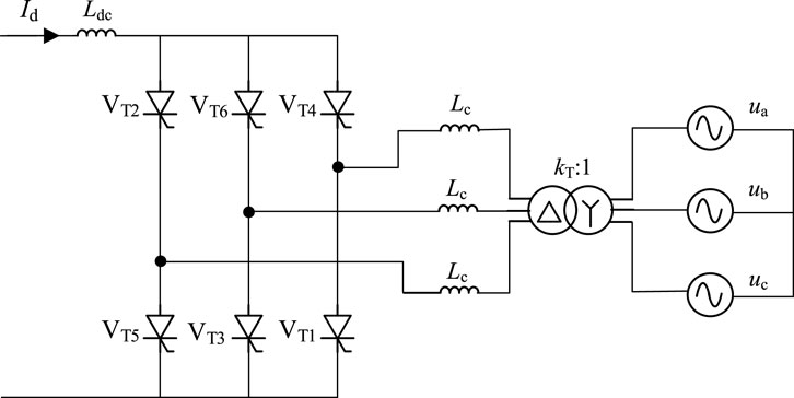
Figure 1 is a schematic diagram of the three-phase full-wave bridge circuit structure (Jiang et al., 2023b), which is also the structure adopted by LCC in conventional DC systems. In this diagram, ua, ub, and uc represent the three-phase AC phase voltages of the system, respectively. Lc represents the system’s equivalent commutation inductance, Ldc represents the smoothing inductance, Id represents the DC current, kT represents the transformation ratio of the converter transformer, and VTi (i = 1–6) represents the thyristor converter valve on the corresponding arm of the LCC.
During normal operation of the converter, one converter valve is conducting in both the upper and lower arms of the converter’s commutation valves. The two conducting valves have adjacent numbers (considering VT6 adjacent to VT1). When the LCC undergoes a state transition, the already conducting valve in the upper or lower arm will be turned off, and the valve that was previously off will be turned on in sequence. The alternating conduction process of the valves in the upper/lower arms is known as the commutation process.
The control strategy of the LCC converter station consists of two parts: the control strategy for the rectifier side LCC and the control strategy for the inverter side LCC. The control structure is shown in Figure 2.
In Figure 2, Idr and Idi represent the DC currents on the rectifier and inverter sides, respectively. Udr and Udi represent the DC voltages on the rectifier and inverter sides, respectively. βrec and βinv represent the lead trigger angle command values for the rectifier and inverter sides, respectively. Id_ord is the settable current command value, Idr_ord is the current command value on the rectifier side, and γref is the rated arc extinction angle. γ is the system’s arc extinction angle, which takes the minimum value from the previous cycle. βcc and βcea represent the lead trigger angle command values corresponding to constant current control and constant arc extinction angle control on the inverter side, respectively. The control mode corresponding to the larger of the two values determines the current control mode of the converter.
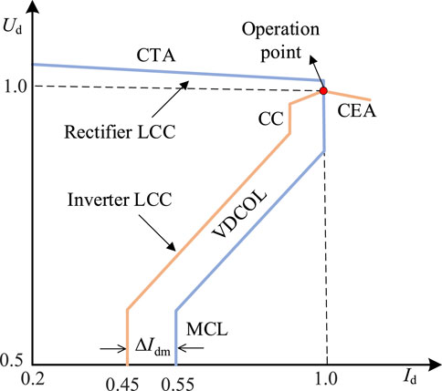
The CE control strategy employed in LCC converter stations falls between the CEA and CC control modes on the inverter side. Additionally, the VDCOL control mode is implemented on both the rectifier and inverter sides. Its purpose is to limit the DC current when the DC voltage is too low, thereby reducing the transmitted DC power. This aids in the rapid recovery of the DC system after a fault and prevents commutation failures. The control characteristic curves for the rectifier and inverter side LCCs are shown in Figure 3. Under normal system operation, the rectifier side LCC operates in constant current control mode, while the inverter side LCC operates in constant extinction angle control mode.
2.2 The basic structure of energy-storage system
The grid-connected structure of the energy storage system is shown in Figure 4. Due to the intermittency and volatility of solar energy, the output of the photovoltaic system fluctuates accordingly. To ensure a stable power supply, the energy storage system assists the photovoltaic system as the main control power source for the black start. By storing and releasing energy, it smooths out the photovoltaic output and ensures that the system provides continuous and stable power to the load.
Figure 5 represents the typical control structure of an ES system. In the diagram, iB denotes the DC current output by the energy storage system; Udc represents the DC voltage output by the DC/DC converter; fref is the system reference frequency, which goes through a phase-locked loop to obtain the phase angle θ; uabc stands for the measured value of the grid-side voltage; iL_abc signifies the filter inductor current; udq_ref is the given outer-loop voltage reference signal; idq_ref represents the inner-loop current reference signal generated by the outer-loop control; and udq and idq are the voltage and current in the dq axis after coordinate transformation.
In the typical control structure of the energy storage system, the bidirectional DC/DC converter maintains a constant DC voltage by controlling the DC current output from the energy storage battery, enabling bidirectional energy transfer between the energy storage system and the grid. The PCS of the energy storage system employs V/f control to provide stable voltage and frequency support for grid restoration. Additionally, the energy storage system balances issues such as mismatches between system output and load power, offering stable and reliable electrical support to the grid.
3 The coordinated low frequency oscillation damping control strategy based on robust theory
In this section, by improving the existing robust damping control methods and considering the interaction between multiple control loops, a coupled robust damping control method based on a multi-input multi-output (MIMO) system model is proposed. Based on the analysis of system oscillation characteristics, appropriate feedback signals and controller installation locations are selected using the modal ratio index. The Total Least Squares-Estimation of Signal Parameters via Rotational Invariance Techniques (TLS-ESPRIT) algorithm is utilized to identify a reduced-order system model. Finally, a coupled robust controller is designed.
3.1 The improved robust controllers
For a MIMO system, when designing a robust damping controller using mixed H2/H∞ control theory, the system structure is shown in Figure 6 and Equation 1. In the figure: G(s) represents the controlled system; K(s) represents the control system; εi (i = 1,2,⋯,n) represents the controller output; r represents the reference input; u represents the system input; y represents the system output; W1(s), W2(s), and W3(s) are weighting functions; z∞1, z∞2, and z2 are reference outputs for measuring system performance; wi (i = 1,2,⋯,n) represents external disturbances to the system. The mode of Figure 6 is as follows (Apkarian et al., 2001):
In the formula: x represents the system state variables; A represents the state matrix; B1 represents the disturbance gain matrix; B2 represents the control input matrix; C∞, D∞1, and D∞2 are coefficient matrices for state variables, disturbance variables, and input variables related to the H∞ index, respectively; C2, D21, and D22 are coefficient matrices for state variables, disturbance variables, and input variables related to the H2 index, respectively; Dy1 and Dy2 are direct transmission matrices corresponding to w and u, respectively; C represents the system output matrix.
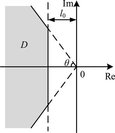
The power grid itself has a complex structure, which inherently leads to uncertainties in modeling and disturbances. But if the poles of the system in Figure 6 are constrained in the shadow area plotted in Figure 7, the small stability can be guaranteed. In the figure, l0 represents the minimum distance from the pole configuration region to the imaginary axis, and θ represents the maximum argument of the pole configuration region. This can be described using matrix inequalities as follows Equations 2, 3:
The above problem that make sure the poles in certain zones can be realized by the LMI toolbox, which can be found the in mathematics math software, namely the MATLAB.
The H∞ performance index reflects the system’s effectiveness in suppressing disturbances, which can use the following equation to calculate:
From Equation 4, it can be seen that it represents the peak value pk{·} of the maximum singular value σmax(·) of the system’s frequency response. From a time-domain perspective, it represents the steady-state gain in the worst-case scenario for sinusoidal inputs of any frequency. According to the bounded real lemma, the necessary and sufficient condition to satisfy the controller design objectives is the existence of a symmetric positive definite matrix P∞, such that the following Equation 5 holds:
In the formula, E represents the identity matrix.
The H2 performance can be calculated by Equation 6, which is as follow.
In the formula, tr(·) represents the trace of the matrix, and [T2*(jω)] is the conjugate transpose of T2(jω). From Equation 6, it can be seen that the H2 norm of T2(s) is equal to the root mean square value of the output energy of the system’s impulse response. The necessary and sufficient condition to satisfy the controller design objectives is the existence of symmetric positive definite matrices P2 and Q, such that Equations 7–9 hold.
The mixed H2/H∞ problem then can be described as the follow Equation 10 optimization problem:
where, α + β = 1.
3.2 Small-gain theorem for robust stability of systems considering uncertainty
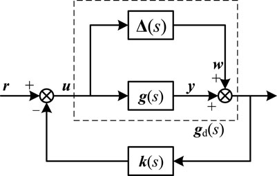
Considering the constantly changing operating conditions and working states of the actual power system, it will cause changes in the system’s small perturbation offline identification model. Additionally, there is an unavoidable truncation error between the system’s true transfer function model and the reduced-order transfer function model obtained through small perturbation identification methods. As shown in Figure 8, let g(s) represent the reduced-order transfer function matrix obtained using the identification method, gd(s) represent the actual transfer function matrix of the system, and Δ(s) represent the identification error. Then we have Equation 11:
The small-gain theorem can be described as follows: when operating conditions change, the necessary and sufficient condition for the system shown in Figure 8 to remain stable is that Equation 12 holds true:
In the formula, Guw(s) represents the closed-loop transfer function from w to u. The smaller the value of
3.3 Coupled robust control for MIMO systems
In large-scale AC/DC interconnected power systems, multiple oscillation modes often coexist, requiring the use of multiple HVDC or FACTS auxiliary control functions to enhance damping for multiple oscillation modes. A common approach involves pairing multiple modulation signals with control loops, designing damping controllers using a specific damping channel to enhance damping for a particular oscillation mode. For the MIMO multivariable decentralized control system shown in Figure 6, if ui → yi (i = 1,2,⋯,n) is treated as an independent SISO system, due to the inherent coupling in the electrical system, the decentralized robust damping controller designed accordingly does not reflect the interaction between multiple variables and may even worsen the damping effect of the controller. However, in complex control loop situations, it is sometimes difficult to eliminate the coupling that exists in the loop using controllers designed based on decoupling methods. Therefore, this chapter considers the interaction between multiple control loops in the MIMO system and proposes a coupled robust damping control method.
For a control loop consisting of any input variable uj (j = 1,2,⋯,n) and any output variable yi (i = 1,2,⋯,n), when all other loops are open, the transfer function from uj to yi is defined as gij. And let the transfer function matrix G be Equation 13:
The control system K is as Equation 14 shows.
In the formula, kii (i = 1,2,⋯,n) represents the transfer function of the controller from the output yi to the reference input ri.
If the reference input is set to zero, the system output variables can be expressed as:
In the formula,
Based on Equation 15, after considering the coupling effect of other control loops on this control loop, the transfer function Gij from uj to yi can be expressed as Equation 16 show:
Taking a two-input two-output system as an example, to reflect the interactive coupling that exists in multiple control loops, controllers k21 and k12 that reflect cross-coupling should be designed based on the system described by G12 and G21, in addition to the controllers k11 and k22 that have already been designed.
3.4 System identification and feedback signals selections
The TLS-ESPRIT algorithm can be used for both simulation data analysis and system identification. Compared to the Prony method, this algorithm demonstrates stronger resistance to noise and interference, effectively recovering harmonics and obtaining the attenuation characteristic parameters of signals. It is one of the most commonly used methods for offline identification of low-frequency oscillations in power systems. The general idea of this algorithm is to construct a Hankel matrix H using sampled data and then decompose it into signal subspace and noise subspace through singular value decomposition. This allows for the calculation of the signal’s rotation operator, which can further be used to obtain the oscillation frequency, attenuation factor, and other characteristic parameters of each oscillation mode (Chen et al., 2019).
When designing controllers, to ensure good damping effects on the system’s weakly damped modes and minimize coupling effects on other modes, the dominant mode ratio (DMR) is commonly used as an indicator to measure the damping effect per unit of control output. This metric assesses the relative strength of feedback signals and the damping performance of the controller on a specific oscillation mode. Compared to the residue method, this indicator eliminates the influence of dimensions, allowing for direct comparisons between different types of signals. The calculation formula for the dominant mode ratio (η) is as follows Equation 17 shows (He et al., 2007; Wu et al., 2024; Li Jiajun et al., 2024):
In the formula:
Different perturbations in the system can cause variations in the initial amplitude |zk(0)| of different oscillation modes. Therefore, in this paper, when calculating the dominant mode ratio (DMR) indicator, the average value of DMR obtained after applying different perturbations to the system is used.
In summary, the steps for designing a controller are as follows: First, small perturbations are applied to the system at steady state, and the TLS-ESPRIT algorithm is used. Based on the dominant mode ratio indicator, appropriate feedback signals in the system are selected, and a MIMO system model is established corresponding to the HVDC and energy storage control channels. The system’s transfer function is obtained and reduced in order. Then, using robust control methods and considering the coupling effects between different control loops, a coupled robust damping controller is designed. Finally, it is attached to the corresponding control loop, and its effectiveness is verified through actual system simulation.
And the detail MIMO system identification procedures can be described as follows: A step disturbance is applied at the setpoint of the DC power, and the changes in the speed differences of key generators are measured respectively. Subsequently, the TLS-ESPRIT algorithm is utilized to identify the transfer functions from the DC system to various generators. Concurrently, another step disturbance is imposed on the setpoint of the constant power control in the outer loop of the energy storage system, and the changes in the speed differences of the key generators are again measured individually. The TLS-ESPRIT algorithm is then employed to identify the transfer functions from the energy storage system to different generators. Ultimately, the MIMO (Multi-Input Multi-Output) transfer functions from both the DC transmission and the energy storage system to the speeds of key generators are obtained.
4 Case study
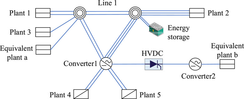
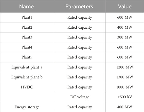
To validate the proposed strategy, simulations were conducted using PSCAD software. The AC-DC hybrid system, as illustrated in Figure 9, was established, and its parameters are presented in Table 1. In this hybrid HVDC system, energy storage and HVDC are used as low frequency oscillation damping controllers.
The oscillation modes of the system identified by the TLS-ESPRIT algorithm are shown in Table 2. Generally, modes with a damping ratio less than 5% are considered as weakly damped modes. As can be seen from the table, there are two weakly damped oscillation modes in the system, with oscillation frequencies of 1.61 Hz and 0.82 Hz, respectively. Among them, the damping ratio of the oscillation frequency of 1.61 Hz is close to 0, which is the dominant oscillation mode of the system.
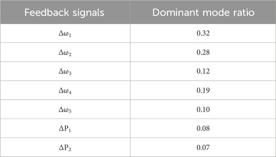
The feedback signals of the controllers are also evaluated based on dominant mode ratio index. The reason why we choose rotor speed and active power as the feedback signal is that the low frequency oscillations are related to the active power generated by plants. Such that the signals of rotor speed, active power can all be selected as the feedback signals. According to Table 3, it can be seen that the rotor speed deviation of plant1 and plant2, namely Δω1 and Δω2, are the most two suitable input signals for controller design, as they have bigger index values. The following parts will use the proposed method to suppress the low frequency oscillations, where the traditional PI controllers are also designed for comparison.
4.1 Case 1
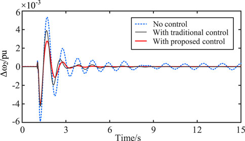
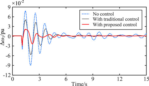
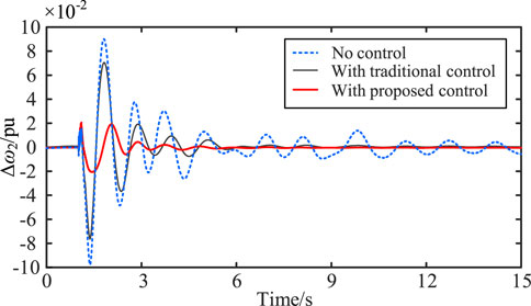
At 1s, a single-phase grounding short-circuit fault occurs on Line 1, with a duration of 0.1s. We compare the feedback signals Δω1 and Δω2 under three conditions: without controller, with coupled robust damping controller, and with traditional controller. The suppression effect of the Δω1 is shown in Figure 10, and the suppression effect of the Δω2 is shown in Figure 11. In the figures, both Δω1 and Δω2 are per unit values.
It is obvious that under case 1 condition, both the coupled robust controller proposed in this paper and the traditional classical controller can suppress low-frequency oscillation. However, the coupled robust controller demonstrates better recovery characteristics and has a more effective suppression effect compared to the traditional controller, which proves the advantages of the proposed method in this paper.
4.2 Case 2
At 1s, the generator in plant 3 is disconnected. The comparison of the suppression effects on the oscillation modes of Δω1 and Δω2 under this operating condition is shown in Figures 12, 13.
Similarly, under case 2 condition, both the coupled robust controller proposed in this paper and the traditional classical controller can also suppress low-frequency oscillation. And the coupled robust controller also can obtain better results. It proves that the robustness of the proposed method can be guaranteed when different faults happen.
4.3 Case 3
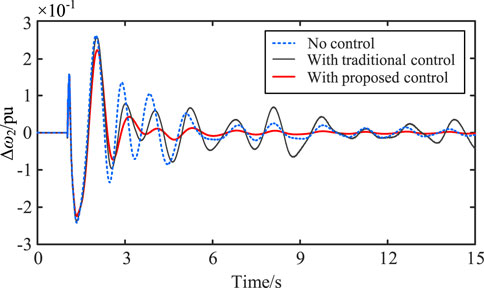
At 1 s, a three-phase short-circuit fault occurs in the system, which is cleared after 0.1 s. The comparison of the suppression effects of the Δω1 and Δω2 oscillation modes in this scenario is shown in the Figures 14, 15.
As shown in the Figures 14, 15, when the system experiences a more severe three-phase short-circuit fault compared to case 1 and case2, during the initial oscillation phase, the traditional damping controllers can suppress the low-frequency oscillation of the system. However, for a considerable period after the fault is cleared, the traditional control is unable to fully restore the system to a stable operating state. This is because the two traditional controllers are independently designed based on the linearized models of two small-disturbance SISO (Single-Input Single-Output) systems, and they do not account for or eliminate the negative interactions between the multiple control loops in the MIMO (Multi-Input Multi-Output) system. As a result, the system may experience underdamped oscillations, which weaken the damping effect of the controllers. On the other hand, the controller designed based on MIMO control considerations not only considers the interactions between control loops during its design but also possesses robustness, ensuring stable operation of the system under various conditions.
5 Conclusion
This study explored the multi-resource and multi-objective collaboration damping control strategy based on HVDC and energy-storage system. Drawing from previous analyses and simulation results, several key conclusions can be summarized, as follows:
(1) Due to the complex grid structure and numerous control devices in the actual system, it is difficult for decentralized damping controllers designed based on the decoupling of control loops to exert their advantages. In this paper, a coupled robust damping controller considering the interaction between multiple control loops is designed based on the MIMO system, avoiding decoupling in complex control loop situations. Compared to traditional damping control methods, this approach demonstrates good suppression effects under various operating conditions.
(2) The controller is implemented through DC and energy storage systems, extending the control capabilities of existing system equipment. Simulation results indicate that compared to traditional damping controllers, the coupled robust controller is insensitive to system perturbations and can effectively suppress low-frequency oscillation of the system under various disturbances and failures, demonstrating strong robust performance.
(3) The proposed control method can be extended to systems with more input and output signals, providing a reference for the stable operation and control of complex power grids, including scenarios such as energy storage systems equipped with renewable energy and VSC-HVDC transmission systems.
Data availability statement
The original contributions presented in the study are included in the article/supplementary material, further inquiries can be directed to the corresponding author.
Author contributions
BZ: Conceptualization, Formal Analysis, Investigation, Writing–original draft, Writing–review and editing. YX: Software, Writing–original draft, Writing–review and editing. XS: Data curation, Writing–review and editing. XJ: Supervision, Writing–review and editing.
Funding
The author(s) declare that financial support was received for the research, authorship, and/or publication of this article. This work was supported by the State Grid Sichuan Electric Power Research Institute Science and Technology Project under Grant 52199723001F. (Mechanism of the impact of abnormal states on the stability of new power systems and technology for resilience enhancement).
Conflict of interest
The authors declare that the research was conducted in the absence of any commercial or financial relationships that could be construed as a potential conflict of interest.
Publisher’s note
All claims expressed in this article are solely those of the authors and do not necessarily represent those of their affiliated organizations, or those of the publisher, the editors and the reviewers. Any product that may be evaluated in this article, or claim that may be made by its manufacturer, is not guaranteed or endorsed by the publisher.
References
Abd El-Kareem, A. H., Abd Elhameed, M., and Elkholy, M. M. (2021). Effective damping of local low frequency oscillations in power systems integrated with bulk PV generation. Prot. Control Mod. Power Syst. 6 (4), 1–13.
Apkarian, P., Tuan, H. D., and Bernussou, J. (2001). Continuous-time analysis, eigenstructure assignment, and H/sub 2/synthesis with enhanced linear matrix inequalities (LMI) characterizations. IEEE Trans. Automatic Control 46 (12), 1941–1946. doi:10.1109/9.975496
Bento, M. E. (2021). A hybrid particle swarm optimization algorithm for the wide-area damping control design. IEEE Trans. Industrial Inf. 18 (1), 592–599. doi:10.1109/tii.2021.3054846
Chen, J., Jin, T., Mohamed, M. A., and Wang, M. (2019). An adaptive TLS-ESPRIT algorithm based on an SG filter for analysis of low frequency oscillation in wide area measurement systems. Ieee Access 7, 47644–47654. doi:10.1109/access.2019.2908629
He, J., Li, L., Chen, H., Wu, X., and Li, P. (2007). Selection of feedback signal for power system damping controller based on wide area measurements. Automation Electr. power Syst. 31 (9), 6–10.
Hengfeng, D., Zheng, X. U., and Hongyang, H. U. A. N. G. (2016). Grid side damping control technologies of low frequency oscillation of ultra high voltage transmission systems for large-scale energy bases. High. Volt. Eng. 42 (2), 571–580.
Jiang, Q., Li, B., Liu, T., Blaabjerg, F., and Wang, P. (2023b). Study of cyber attack’s impact on LCC-HVDC system with false data injection. IEEE Trans. Smart Grid 14 (4), 3220–3231. doi:10.1109/tsg.2023.3266780
Jiang, Q., Tao, Y., Li, B., Liu, T., Chen, Z., Blaabjerg, F., et al. (2023a). Joint limiting control strategy based on virtual impedance shaping for suppressing DC fault current and arm current in MMC-HVDC systems. J. Mod. Power Syst. Clean Energy 11 (6), 2003–2014. doi:10.35833/mpce.2022.000571
Jiang, Q., Zeng, X., Li, B., Wang, S., Liu, T., Chen, Z., et al. (2022). Time-sharing frequency coordinated control strategy for PMSG-based wind turbine. IEEE J. Emerg. Sel. Top. Circuits Syst. 12 (1), 268–278. doi:10.1109/jetcas.2022.3152796
Jing, Y., Tong, W., and Jingtian, B. (2020). Robust damping control of subsynchronous oscillation in power system with direct-drive wind turbines [J]. Automation Electr. Power Syst., 44(03), 56–65.
Li, J., Shi, H., Li, B., Jiang, Q., Yin, Y., Zhang, Y., et al. (2024b). Fault ride-through method for interline power flow controller based on DC current limiter. Electronics 13 (6), 1038. doi:10.3390/electronics13061038
Li, Q., Li, B., Jiang, Q., Liu, T., Yue, Y., and Zhang, Y. (2024a). A novel location method for interline power flow controllers based on entropy theory. Prot. Control Mod. Power Syst. 9 (3), 70–81. doi:10.23919/pcmp.2023.000504
Ma, W., Gao, J., Zhou, G., Zhang, Y., Zhang, K., Han, J., et al. (2021). Investigation and control of damping in VSC–mtdc system with DC circuit breakers. Symmetry 13 (11), 2037. doi:10.3390/sym13112037
Ma, Y., Zhang, J., Jiang, Y., and Zhao, S. (2017). Additional robust damping control of wide-area power system with multiple time delays considered. Trans. China Electrotech. Soc. 32 (6), 58–66.
Ming, X., Peng, L., Kun, Z., and Zhifei, L. (2011). “Operation and evaluation of the coordinated HVDC damping control system of China Southern Power Grid,” in 2011 4th international conference on electric utility deregulation and restructuring and power technologies (DRPT) (IEEE), 94–98.
Sheta, A. N., Abdulsalam, G. M., Sedhom, B. E., and Eladl, A. A. (2023). Comparative framework for AC-microgrid protection schemes: challenges, solutions, real applications, and future trends. Prot. Control Mod. Power Syst. 8 (2), 24–40. doi:10.1186/s41601-023-00296-9
Tang, Y., He, H., Ni, Z., Wen, J., and Huang, T. (2015). Adaptive modulation for DFIG and STATCOM with high-voltage direct current transmission. IEEE Trans. Neural Netw. Learn. Syst. 27 (8), 1762–1772. doi:10.1109/tnnls.2015.2504035
Tao, Y., Li, B., Dragičević, T., Liu, T., and Blaabjerg, F. (2020). HVDC grid fault current limiting method through topology optimization based on genetic algorithm. IEEE J. Emerg. Sel. Top. Power Electron. 9 (6), 7045–7055. doi:10.1109/jestpe.2020.3026026
Verma, N., Kumar, N., Gupta, S., Malik, H., and Márquez, F. P. G. (2023). Review of sub-synchronous interaction in wind integrated power systems: classification, challenges, and mitigation techniques. Prot. Control Mod. Power Syst. 8 (2), 17–26. doi:10.1186/s41601-023-00291-0
Wen, M., Shi, H., Li, B., Jiang, Q., Liu, T., and Ding, C. (2023). Research on the coordinated recovery strategy based on centralized electric vehicle charging station. Energies 16 (14), 5401. doi:10.3390/en16145401
Weng, H., Xu, Z., Xu, F., Liu, Z., and Hua, W. (2013). Robust design of HVDC supplementary controllers based on WAMS signals. Zhongguo Dianji Gongcheng Xuebao Proceedings Chin. Soc. Electr. Eng. 33 (4), 103–109.
Wilches-Bernal, F., Byrne, R. H., and Lian, J. (2019). Damping of inter-area oscillations via modulation of aggregated loads. IEEE Trans. Power Syst. 35 (3), 2024–2036. doi:10.1109/tpwrs.2019.2948116
Wu, R., Jiang, Q., Li, B., Liu, T., and Zeng, X. (2024). Control method for ultra-low frequency oscillation and frequency control performance in hydro–wind power sending system. Electronics 13, 3691. doi:10.3390/electronics13183691
Yantong, Z. H. O. U., Lili, H. A. O., and Haohao, W. A. N. G. (2020). Analysis and suppression of SSO at sending/receiving end in VSC-HVDC system connected large-capacity wind farms. Electr. Power Autom. Equip. 40 (3), 100–106.
Keywords: damping control, multi-objective, HVDC, energy storage, control strategy
Citation: Zhou B, Xu Y, Sun X and Jiang X (2024) Research on the multi-objective collaboration damping control strategy based on multi-resource. Front. Energy Res. 12:1498273. doi: 10.3389/fenrg.2024.1498273
Received: 18 September 2024; Accepted: 29 November 2024;
Published: 13 December 2024.
Edited by:
Wenping Zhang, Tianjin University, ChinaReviewed by:
Renxin Yang, Shanghai Jiao Tong University, ChinaBo Pang, Southwest Jiaotong University, China
Copyright © 2024 Zhou, Xu, Sun and Jiang. This is an open-access article distributed under the terms of the Creative Commons Attribution License (CC BY). The use, distribution or reproduction in other forums is permitted, provided the original author(s) and the copyright owner(s) are credited and that the original publication in this journal is cited, in accordance with accepted academic practice. No use, distribution or reproduction is permitted which does not comply with these terms.
*Correspondence: Bo Zhou, emJ2X3MxNjNAMTYzLmNvbQ==
 Bo Zhou
 Yunyang Xu1,2