- 1China Energy Engineering Group Zhejiang Electric Power Design Institute Co., Ltd., Hangzhou, China
- 2Key Laboratory of Power System Intelligent Dispatch and Control of Ministry of Education, School of Electrical Engineering, Shandong University, Jinan, China
Since the large-scale integration of renewable energy sources into the AC grid has led to a relative decline in the voltage support capacity of the grid and the deterioration of the voltage dynamic at the grid connection point, especially under fast-scale conditions, the voltage disturbance has become more obvious. To improve the dynamic characteristics of the electromagnetic transient voltage at the grid connection point, this paper uses a practical dynamic damping method to analyze the impact of the converter current inner loop, feedforward voltage, and other links on the dynamic performance of the electromagnetic transient voltage. First, the current inner loop dynamic in the converter’s synchronous coordinate is converted into an equivalent transfer function in the stationary coordinate, and the transfer function between the transient voltage disturbance at the grid connection point and the inner loop current output is established. On this basis, the Bode diagram and the vector diagram of the transfer function in the weak damping frequency band are used to analyze the dynamic damping of the current inner loop parameters and voltage feedforward filter parameters on the voltage disturbance at the grid connection point. The results indicate that moderately increasing the current inner loop bandwidth or reducing the feedforward filter bandwidth can help enhance the electromagnetic transient voltage stability of the grid connection point, but increasing the current inner loop bandwidth will worsen the low-frequency damping characteristics and reduce the feedforward filter bandwidth will still help increase low-frequency damping.
1 Introduction
The dynamic characteristics of frequency and voltage have always been critical characteristics of power quality in the power system. In traditional power systems, the focus is mainly on the electromechanical time-scale frequency dynamics dominated by the synchronous machine rotor, while in the electromechanical time-scale, voltage dynamics are often described using algebraic equations (Kundur, 1994; Wu et al., 2023). Therefore, traditional power systems lack research and attention to faster scale voltage dynamics (Vu et al., 1995; Cheng et al., 2024), and the practical factor is that the synchronous machine excitation control system provides sufficient voltage support capability (Huang et al., 2018; Löf et al., 1993).
With the large-scale integration of power electronic devices such as photovoltaics, wind power, flexible DC, and flexible AC transmission into the power grid, the sensitivity of the power grid response to electromagnetic time-scale disturbances continues to increase. Taking the doubly fed induction generator (DFIG) as an example, the rapid fluctuation of grid voltage can trigger negative sequence magnetic potential fluctuations in the electromagnetic time scale of DFIG, making it difficult to achieve the low voltage ride through (LVRT) control goal smoothly (Xu et al., 2012; Li et al., 2022). In addition, multi-scale cascade control structures are commonly used in various new energy generation equipment types. For example, new energy converters commonly use control loops such as phase-locked loops (PLL), current inner loops, and power outer loops, which require the dynamic analysis of grid voltage affected by multi-scale cascade control of converters to be extended to more time scales (Zhou et al., 2014; Hu et al., 2023). In summary, as the scale of power electronic equipment integration continues to increase, the dynamic characteristics of electromagnetic time scale grid voltage will become one of the focuses of power quality issues (Milano, 2016; Hansen et al., 2019; Breyer et al., 2022).
The voltage stability analysis in traditional power systems often uses the quasi-steady state phasor method to study the relationship between reactive power and voltage amplitude in power flow equations (Xie et al., 2012; Simpson-Porco and Bullo, 2016; Song et al., 2019; Li et al., 2021; Chu and Teng, 2023; Chen et al., 2019; Chen et al., 2020). However, the multi-scale cascade control of power electronic equipment is aimed at controlling instantaneous values. Therefore, traditional voltage stability analysis models based on vector methods make it difficult to explain the impact of power electronic control loops on the dynamic characteristics of power grid voltage at the electromagnetic transient time scale (Zhao et al., 2016).
Generally, the voltage dynamics of the power grid are mainly affected by the reactive power or current output. For the widely used grid following converters, their electromagnetic transient scale exhibits external characteristics of the current source, and the control characteristics of instantaneous current will directly affect the dynamic characteristics of the power grid voltage. Zhao et al. (2016) conducted a preliminary analysis of the dynamic voltage characteristics at the electromagnetic scale, but the modeling process lacked detailed derivation, and the proposed scheme only improved the high-frequency characteristics while ignoring the potential adverse effects in the low-frequency range.
This article provides a detailed derivation of the transformation formula for the inner loop controller from the rotating coordinate system of the control system to the three-phase stationary coordinate system. Based on this, the influence of the bandwidth changes of the current inner loop and voltage feedforward filter on the high-frequency and low-frequency ranges of the grid voltage is analyzed.
Research has found that moderately increasing the bandwidth of the current inner loop or reducing the bandwidth of the feedforward filter can help enhance the transient voltage stability at the grid connection point. However, increasing the current inner loop bandwidth will deteriorate the low-frequency damping characteristics, while reducing the bandwidth of the feedforward filter still helps to increase low-frequency damping.
2 Dynamic modeling of transient voltage scale
2.1 Multi-scale voltage control architecture
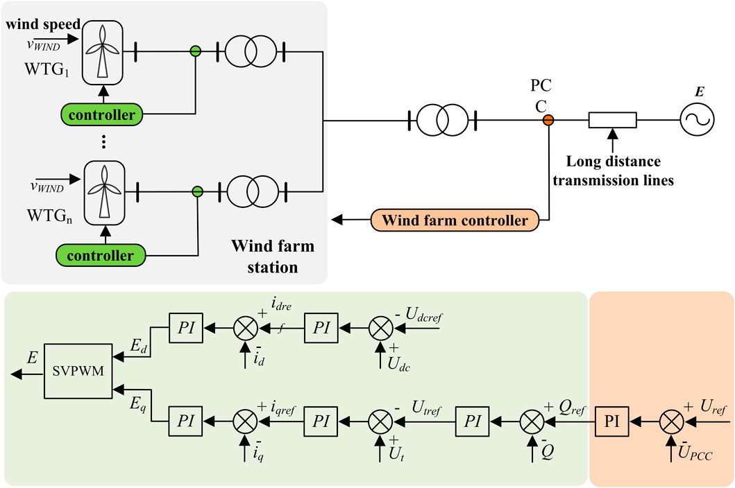
Due to the large number and diverse types of equipment in the power system, a layered multi-scale control structure is traditionally commonly used to meet the multi-time scale frequency and voltage regulation requirements during the operation of the large power grid. This article takes an example of a wind farm composed of direct-drive wind turbine generator. Below is a brief introduction to the voltage control architecture of the existing wind farm station on a time scale from slow to fast. The control structure diagram is shown in Figure 1.
The wind farm controller is responsible for detecting the amplitude of the high-voltage side voltage. For general onshore wind farms, the high-voltage side volt-age level is generally around 220 kV. When the amplitude of the high-voltage side voltage deviates from the set value, the wind farm controller will calculate the reactive power demand and send it to the reactive power compensation equipment and wind turbines in the wind farm. Reactive power compensation equipment, such as static var generator (SVG), has a larger rated capacity, generally about three times that of wind turbines. The reactive power compensation equipment converts the reactive power demand output by the wind farm controller into the command value for voltage control on the medium voltage side. The voltage level on the medium voltage side is generally around 35 kV. The wind turbine also receives the reactive power command value issued by the wind farm controller and converts it into the command value of the low-voltage side voltage control, that is, the command value of the AC voltage outer loop. The low-voltage side voltage level is generally 0.69 kV.
The above voltage control at all levels covers multiple voltage levels such as station terminal voltage and wind turbine terminal voltage, covering voltage control issues from electromechanical to medium to long-term time scales on a time scale. These scale voltage controls also exist in traditional power systems. In addition, power electronic converters have a much faster response speed than traditional synchronous generators, thus also possessing faster scale voltage control that traditional power systems do not have, i.e., electromagnetic transient voltage/reactive power control at the current inner loop scale. The inverter controls the transient voltage in the electromagnetic transient time scale by controlling the inner loop current command, such as the q-axis current.
This article focuses on the transient voltage dynamic response problem at the electromagnetic transient scale. The following text will establish a transfer function model for the controller and transmission line at this time scale.
2.2 Dynamic equivalence model of inner loop scale
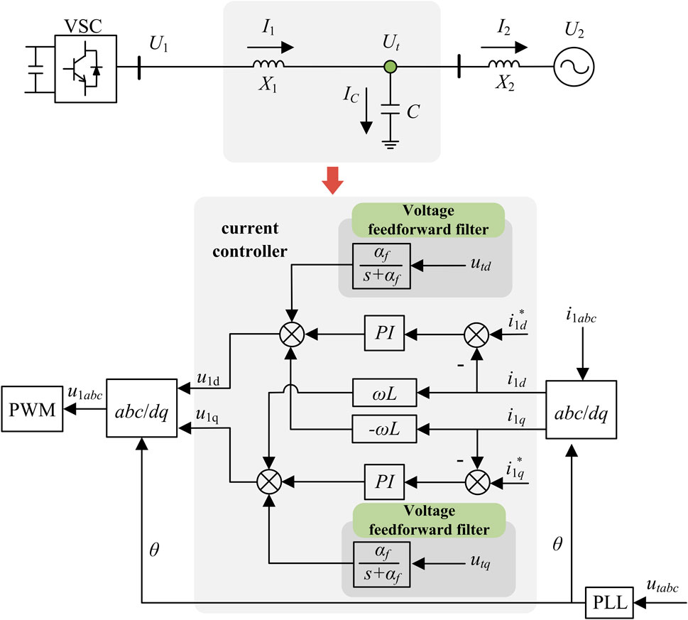
This article aims to analyze the instantaneous voltage dynamic characteristics of a voltage source converter (VSC) single-machine infinite bus system. Therefore, a single machine-connected system with an LC filter and AC line connected to the grid, as shown in Figure 2, is established to simplify the analysis process. Among them, U1 and I1 represent the internal potential and output current of the inverter, Ut represents the grid voltage, and IC and I2 represent the current flowing through the filter capacitor and the current flowing through the AC line, respectively.
The filtering capacitor at the top of Figure 2 serves as a low resistance path for high-frequency harmonics, reducing the harmonic component in the output current I1 of the inverter. The filtering capacitor voltage Ut is used as the grid voltage of the converter, and its dynamic characteristics are the focus of this article.
To analyze the voltage dynamics at the grid connection point, it is necessary to establish a dynamic model of the VSC inverter control system. For the time scale of the current inner loop, the dynamic model needs to take into account the inner loop PI controller, voltage feed-forward (VFF) filter, and other links. Below Figure 2 is a schematic diagram of the control architecture in the time scale of the VSC current inner loop, where the subscript containing abc represents the three-phase AC signal and the subscript containing dq represents the DC signal in the rotating coordinate system of the controller.
Below are the dynamic equivalent models for the current inner loop, voltage feedforward filter, and AC power grid, respectively. The main idea of modeling is to adopt a certain degree of approximation for the above links, and convert the transfer function of the rotating coordinate system (subscript dq) to the stationary coordinate system (subscript αβ), finally convert it to a three-phase stationary coordinate system (subscript abc).
The current inner loop of the inverter adopts proportional integral control (PI) based on the rotating coordinate system, as shown in Figure 2. Ignoring coupling terms ωL that have a relatively small impact on dynamic characteristics, the input-output and transfer function of the current inner loop can be expressed as follows:
where the input and output variables have self-illumination in Figure 2, which will not be further introduced here. Kp and Ki represent the proportion and integration coefficients in PI control, s represents the Laplace operator, Gdq(s) represents the transfer function matrix.
There is a relationship between the product of time-domain functions and trigonometric functions and their Laplace transform (Zmood et al., 2001):
where f(t) represents the time-domain function, Lf(t) represents the Laplace transform of f(t), and F represents the result after the Laplace transform.
Taking the time-domain voltage signal as an example, there is a transformation relationship between the time-domain voltage signal in the dq coordinate system and the αβ coordinate system as follows:
After substituting Equation 3 into Equation 2 and applying the same processing to the current signal, the transfer function matrix Gdq(s) in Equation 1 can be used to derive Gαβ(s) in the αβ coordinate system, which is shown in Equation 4.
where ω represents the fundamental frequency.
The electromagnetic transient simulation algorithm of the power system establishes circuit equations in a three-phase stationary reference frame and uses numerical iteration methods to simulate the dynamic process of the system. Therefore, this paper simulates the electromagnetic transient simulation algorithm and establishes the system dynamic equations in a three-phase stationary reference frame. Then, by defining the transformation matrix T in Equation 5 between the αβ coordinate frame and the abc coordinate frame, Gabc(s) can be further obtained from Gαβ(s), which is shown in Equation 6.
where T+ represents the pseudo inverse of matrix T. Equation 7 is a commonly used form of T+.
According to Equation 6, Gabc(s) is approximately a diagonally dominant matrix in the mid to high frequency range, with all diagonal elements being Gc(s), as shown in Equation 8.
The nondiagonal elements are Go(s), which can be calculated by Equation 9.
In order to simplify the analysis and make Gabc(s) approximately decoupled between the three-phase instantaneous current control, this paper adopts the relative gain array (RGA) to analyze the priority of the matrix elements. Bristol proposed RGA (Bristol, 1966), and Grosdidier et al. (1985) further gave relevant proofs of the mathematical properties of RGA. The control theory states that a RGA can be formed for every multiple input multiple output system. Its basic principle is: for a system with g inputs and k outputs, the relative gain λij between the input uj (j = 1, 2, …, g) and the output yi (i = 1, 2, …, k) can be expressed by Equation 10:
where, the numerator represents the mode in which all controls are open-loop; the denominator represents the mode in which all controls are open-loop except for the closed-loop control of the uj-yi loop.
In this paper, the relative gain matrix can be expressed by Equation 11.
where, ⊗ represents the Hadamard product of the matrix; Gabc(s) represents the transfer function matrix at any frequency.
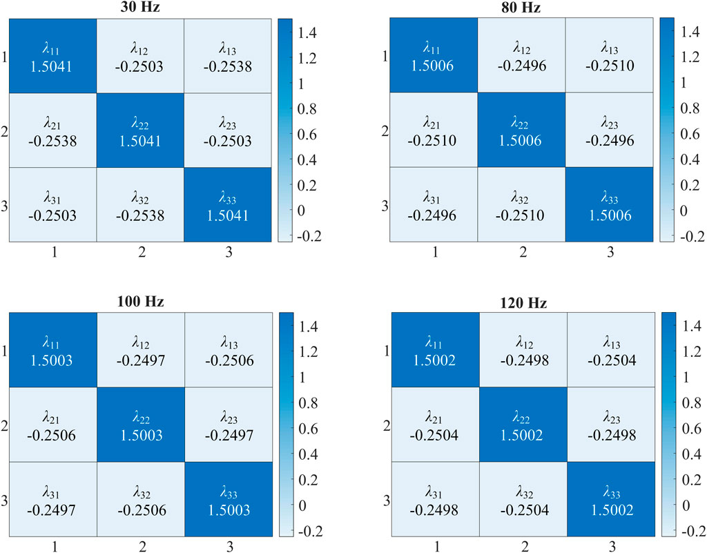
In order to evaluate the correlation of each element in the relative gain matrix, the heat maps of the transfer function Gabc(s) at 30 Hz, 80 Hz, 100 Hz, and 120 Hz are plotted in Figure 3. It can be seen that the value of the diagonal element of RGA is much larger than the nondiagonal elements and the system can be approximately decoupled.
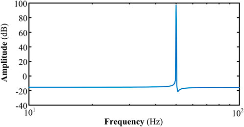
In addition, according to the analysis, it can be seen that the influence of nondiagonal elements Go(s) near the fundamental frequency band is relatively small, as shown in Figure 4, so the Go(s) will be ignored in the following text (Erika and Holmes, 2003).
The above coordinate transformation aims to approximate decoupling between three-phase instantaneous current control, facilitating the use of a single-phase transfer function Gc(s) to analyze the dynamic damping characteristics of the instantaneous voltage at the grid connection point of the inverter in the following text.
In addition, to simplify the analysis process, a first-order transfer function is used to approximate the sampling/calculation delay of voltage feedforward VFF and pulse width modulation (PWM), respectively (Jia et al., 2019). In the abc coordinate system, the above two first-order links are approximated as the following transfer functions.
where G1(s) represents the VFF transfer function, which was originally constructed in the dq rotating coordinate system and is approximated as a first-order transfer function in the abc coordinate system; The approximation process of Gd(s) and G1(s) is the same as, where TPWM represents a sampling delay constant of 1.5 times.
According to Equations 8, 12, 13 above, the transfer function of the current inner loop time scale in the abc coordinate system can be obtained by Equation 14.
where the input and output variables also have self-illumination in Figure 2.
The dynamic model of the three phase symmetrical circuit is shown in Equation 15, mainly describing the differential equation between the instantaneous voltage and current on the LC filter and the line inductance.
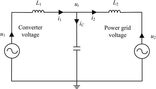
At this point, the dynamic equivalent model of the VSC grid-connected system with the current inner loop scale has been established, and the composition structure of the system is shown in the schematic diagram in Figure 5.
3 Dynamic damping analysis method for electromagnetic transient voltage
As shown in Figure 4, the transient voltage at the grid connection point of the inverter mainly refers to the dynamic voltage ut on the filtering capacitor C. Obviously, the voltage on the filtering capacitor C satisfies the following differential equation.
Equation 16 reflects the dynamic generation mechanism of transient voltage at the grid connection point of the inverter, that is, the voltage on the filtering capacitor C cannot undergo sudden changes, but indirectly generates voltage changes through changes in injected currents on both sides. From another perspective, the output current i1 of the inverter is generated by the deviation between the output voltage u1 of the inverter and the voltage ut of the grid connection point, while the injected current i2 of the grid is generated by the deviation between the voltage ut of the grid connection point and the voltage u2 of the grid connection point.
According to the above analysis, it can be concluded that when the voltage ut at the grid connection point is disturbed by external factors, the currents i1 and i2 on the inverter side and grid side will change. According to Equation 16, the changes in current i1 and i2 will also cause a transient response of the voltage ut at the grid connection point.
The above analysis provides an analytical approach for the dynamic damping of transient voltage at the grid connection point, which involves establishing a small signal model between the voltage disturbance Δut at the grid connection point and the current disturbance Δi1 at the output of the inverter. By observing the frequency domain characteristics of the open-loop system, the dynamic damping distribution of transient voltage at the grid connection point in different frequency bands can be determined.
By linearizing and approximating the dynamic model in Section 2.2, the transfer function between perturbations can be obtained.
Equation 17 consists of four equations, with a total of five variables, namely Δi1, Δi2, Δu1, Δu2, and Δut. When conducting stability analysis, the variation of voltage amplitude in the power grid is generally ignored, i.e., Δu2 = 0. So, according to the first two equations in Equation 17, the transfer function between Δi1 and Δut can be solved, which is shown in Equation 18.
Equations 19, 20 define the transfer functions for analyzing the damping effects of the current inner loop and VFF on transient voltage separately.
From the above two definitions, it can be seen that when the influence of VFF is not considered, analyzing the dynamic damping characteristics represented by GCC(s) can analyze the influence of current inner loop parameters on transient voltage. When considering the influence of VFF, analysis GVFF(s) reveals the influence of VFF parameters on transient voltage.
4 Case study
4.1 Analysis of the influence of controller bandwidth
Here, we analyze the Bode diagram and vector diagram of the above transfer function GCC(s) and GVFF(s) at the current inner loop time scale, respectively, to reflect the influence of controller bandwidth on the dynamic damping of transient voltage at the grid connection point.
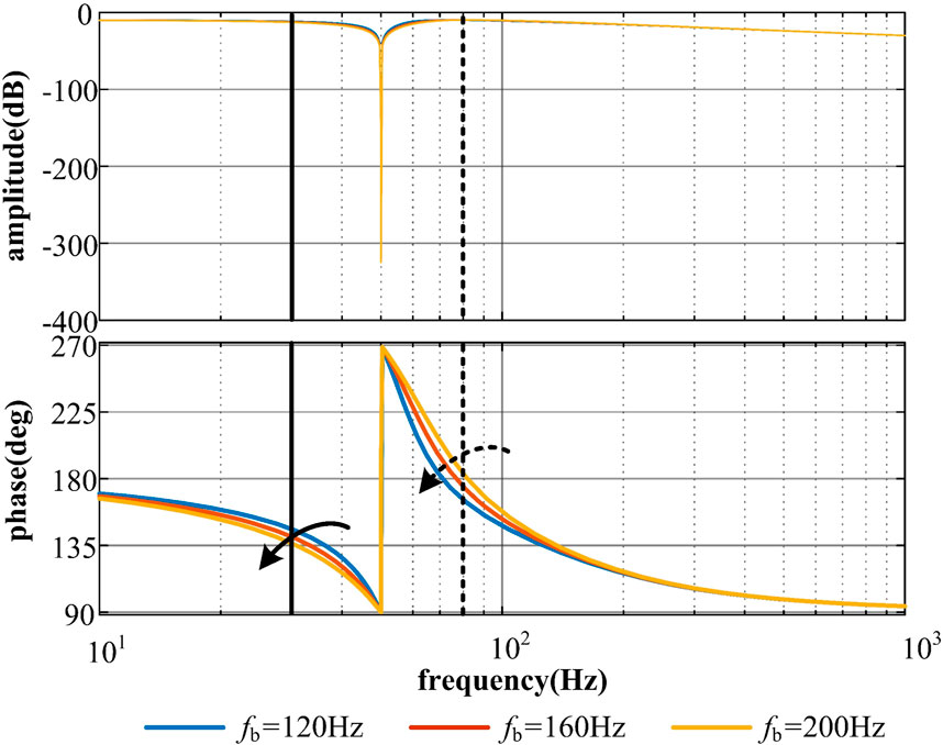
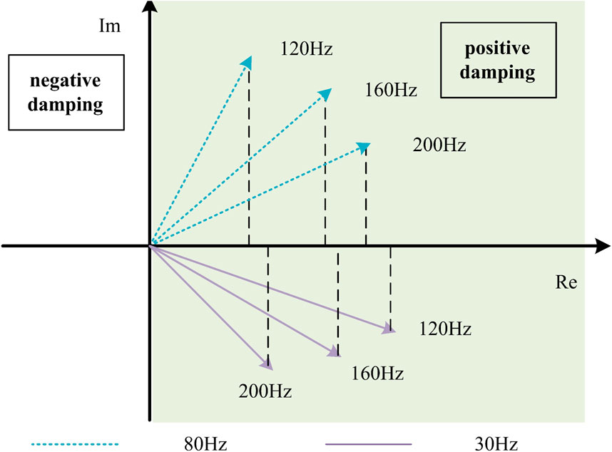
Firstly, analyze the dynamic damping impact of the current inner loop bandwidth on the transient voltage at the grid connection point. Figures 6, 7 show the Bode plot of the transfer function and its corresponding vector plots at 30 Hz and 80 Hz frequency points, respectively. Where fb represents the bandwidth of the current inner loop, and in the case analysis, three types of inner loop control are used: 120 Hz, 160 Hz, and 200 Hz. Here, it can be considered that the time scale of the current inner loop corresponds to the region between 80 and 200 Hz. It can be seen from the dashed line in Figure 7 that as the inner loop bandwidth increases, GCC(s) provides greater positive damping at 80 Hz, which can effectively reduce the output current disturbance of the inverter caused by voltage disturbance at the grid connection point. However, it is also evident from the solid line in Figure 7 that as the inner loop bandwidth increases, GCC(s) provides smaller positive damping at 30 Hz, leading to a deterioration of low-frequency characteristics.
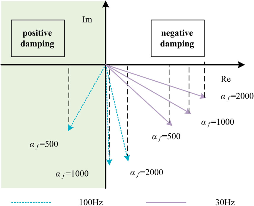
Next, analyze the dynamic damping of voltage feedforward filter parameters on transient voltage at grid points. Take αf as 500, 1000, and 2000, respectively, and draw Bode plots of GVFF(s) and their corresponding vector plots at 30 Hz and 100 Hz frequency points, as shown in Figures 8, 9.
From the results in Figures 8, 9, it can be seen that increasing αf can also increase negative damping in both the frequency range (100 Hz) corresponding to the current inner loop scale and the low-frequency range (30 Hz). Increasing αf corresponds to reducing the bandwidth of the voltage feedforward filter.
4.2 Simulation verification
To verify the effectiveness of the above analysis, this paper built a VSC grid-connected system as shown in Figure 2 on the MATLAB/Simulink platform to observe the changes in PCC point voltage ut under different current inner loop bandwidth and voltage feedforward filter parameter settings.
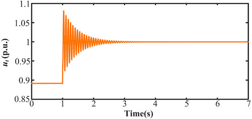
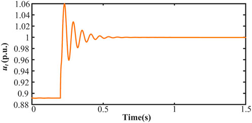
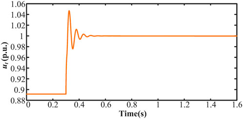
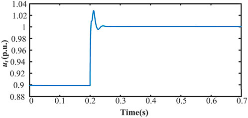
When the inner loop bandwidth is 120 Hz, a disturbance of 0.1 p.u. is added to the voltage at the grid connection point at 1 s. The voltage stabilizes after 3 s, as shown in Figure 10. When the inner loop bandwidth is 160 Hz, a disturbance of 0.1 p.u. is added to the voltage at the grid connection point at 0.2 s. The voltage fluctuation lasts for 0.55 s, as shown in Figure 11. As indicated in Figure 12, when the inner loop bandwidth is increased to 200 Hz, the voltage fluctuation lasts for 0.5 s under the same disturbance.
The above simulation proves that increasing the bandwidth of the current inner loop will increase the positive damping, which can effectively reduce the fluctuation duration caused by voltage disturbances.
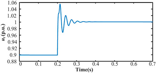
Moreover, the influence of VFF parameters is analyzed below. When the bandwidth of the current inner loop is 200 Hz, the values of αf are set to 100, 200, and 500, respectively. At t = 0.2 s, a 0.1p.u. disturbance is introduced to the voltage of the PCC point, causing voltage fluctuation durations of 0.25 s, 0.17 s, and 0.07 s, as shown in Figures 13–15.
From the above results, it can be seen that as the parameters of the voltage feedforward filter increase, it can provide greater positive damping, and the time required for the grid voltage to recover to a steady state after being disturbed is shorter. Therefore, increasing the parameters of the voltage feedforward filter can effectively reduce the grid voltage disturbance.
5 Conclusion
This paper analyzes the impacts of the current-loop control parameters on the electromagnetic transient voltage performance of the voltage-source converter. The conclusion is that moderately increasing the current inner loop bandwidth or reducing the feedforward filter bandwidth helps to enhance the damping in the high-frequency range of the voltage dynamic. However, increasing the current inner loop bandwidth will deteriorate the low-frequency damping characteristics, while reducing the bandwidth of the feedforward filter still helps to increase low-frequency damping.
Data availability statement
The raw data supporting the conclusions of this article will be made available by the authors, without undue reservation.
Author contributions
XD: Conceptualization, Methodology, Validation, Writing–original draft. HC: Methodology, Investigation, Software, Writing–review and editing. XZ: Conceptualization, Data curation, Formal Analysis, Supervision, Writing–original draft. QS: Supervision, Writing–review and editing. GW: Writing–review and editing, Conceptualization, Formal Analysis, Methodology, Project administration.
Funding
The author(s) declare that no financial support was received for the research, authorship, and/or publication of this article.
Conflict of interest
Authors XD, HC, and XZ were employed by China Energy Engineering Group Zhejiang Electric Power Design Institute Co., Ltd.
The remaining authors declare that the research was conducted in the absence of any commercial or financial relationships that could be construed as a potential conflict of interest.
Publisher’s note
All claims expressed in this article are solely those of the authors and do not necessarily represent those of their affiliated organizations, or those of the publisher, the editors and the reviewers. Any product that may be evaluated in this article, or claim that may be made by its manufacturer, is not guaranteed or endorsed by the publisher.
Supplementary material
The Supplementary Material for this article can be found online at: https://www.frontiersin.org/articles/10.3389/fenrg.2024.1496400/full#supplementary-material
References
Breyer, C., Khalili, S., Bogdanov, D., Ram, M., Oyewo, A. S., Aghahosseini, A., et al. (2022). On the history and future of 100% renewable energy systems research. IEEE Access 10, 78176–78218. doi:10.1109/ACCESS.2022.3193402
Bristol, E. (1966). On a new measure of interaction for multivariable process control. IEEE Trans. Automatic Control 11 (1), 133–134. doi:10.1109/TAC.1966.1098266
Chen, J., Liu, M., Donnell, T. O., and Milano, F. (2020). Impact of current transients on the synchronization stability assessment of grid-feeding converters. IEEE Trans. Power Syst. 35 (5), 4131–4134. doi:10.1109/TPWRS.2020.3009858
Chen, J., Milano, F., and Donnell, T. O. (2019). Assessment of grid-feeding converter voltage stability. IEEE Trans. Power Syst. 34 (5), 3980–3982. doi:10.1109/TPWRS.2019.2920516
Cheng, H., Li, C., Ghias, A. M. Y. M., and Blaabjerg, F. (2024). Dynamic coupling mechanism analysis between voltage and frequency in virtual synchronous generator system. IEEE Trans. Power Syst. 39 (1), 2365–2368. doi:10.1109/TPWRS.2023.3328153
Chu, Z., and Teng, F. (2023). Voltage stability constrained unit commitment in power systems with high penetration of inverter-based generators. IEEE Trans. Power Syst. 38 (2), 1572–1582. doi:10.1109/TPWRS.2022.3179563
Erika, T., and Holmes, D. G. (2003). Grid current regulation of a three-phase voltage source inverter with an LCL input filter. IEEE Trans. Power Electron. 18 (3), 888–895. doi:10.1109/TPEL.2003.810838
Grosdidier, P., Morari, M., and Holt, B. R. (1985). Closed-loop properties from steady-state gain information. Industrial & Eng. Chem. Fundam. 24 (2), 221–235. doi:10.1021/i100018a015
Hansen, K., Breyer, C., and Lund, H. (2019). Status and perspectives on 100% renewable energy systems. Energy 175, 471–480. doi:10.1016/j.energy.2019.03.092
Hu, P., Chen, Z., Yu, Y., and Jiang, D. (2023). On transient instability mechanism of PLL-based VSC connected to a weak grid. IEEE Trans. Industrial Electron. 70 (4), 3836–3846. doi:10.1109/TIE.2022.3181376
Huang, Y., Zhai, X., Hu, J., Liu, D., and Lin, C. (2018). Modeling and stability analysis of VSC internal voltage in DC-link voltage control timescale. IEEE J. Emerg. Sel. Top. Power Electron. 6 (1), 16–28. doi:10.1109/JESTPE.2017.2715224
Jia, K., Yang, Z., Fang, Y., Bi, T., and Sumner, M. (2019). Influence of inverter-interfaced renewable energy generators on directional relay and an improved scheme. IEEE Trans. Power Electron. 34 (12), 11843–11855. doi:10.1109/TPEL.2019.2904715
Li, Y., Fu, L., Meng, K., and Dong, Z. Y. (2021). Assessment and enhancement of static voltage stability with inverter-based generators. IEEE Trans. Power Syst. 36 (3), 2737–2740. doi:10.1109/TPWRS.2021.3062224
Li, Z., Xu, H., Wang, Z., and Yan, Q. (2022). Stability assessment and enhanced control of DFIG-based WTs during weak AC grid. IEEE Access 10, 41371–41380. doi:10.1109/ACCESS.2022.3166810
Löf, P.-A., Hill, D. J., Arnborg, S., and Andersson, G. (1993). On the analysis of long-term voltage stability. Int. J. Electr. Power & Energy Syst. 15 (4), 229–237. doi:10.1016/0142-0615(93)90022-F
Milano, F. (2016). On current and power injection models for angle and voltage stability analysis of power systems. IEEE Trans. Power Syst. 31 (3), 2503–2504. doi:10.1109/TPWRS.2015.2449765
Simpson-Porco, J. W., and Bullo, F. (2016). Distributed monitoring of voltage collapse sensitivity indices. IEEE Trans. Smart Grid 7 (4), 1979–1988. doi:10.1109/TSG.2016.2533319
Song, Y., Hill, D. J., and Liu, T. (2019). Static voltage stability analysis of distribution systems based on network-load admittance ratio. IEEE Trans. Power Syst. 34 (3), 2270–2280. doi:10.1109/TPWRS.2018.2886636
Vu, K., Liu, C.-C., Taylor, C. W., and Jimma, K. M. (1995). Voltage instability: mechanisms and control strategies [power systems]. Proc. IEEE 83, 1442–1455. doi:10.1109/5.481629
Wu, Q. H., Bose, A., Singh, C., Chow, J. H., Mu, G., Sun, Y., et al. (2023). Control and stability of large-scale power system with highly distributed renewable energy generation: viewpoints from six aspects. CSEE J. Power Energy Syst. 9 (1), 8–14. doi:10.17775/CSEEJPES.2022.08740
Xie, L., Chen, Y., and Liao, H. (2012). Distributed online monitoring of quasi-static voltage collapse in multi-area power systems. IEEE Trans. Power Syst. 27 (4), 2271–2279. doi:10.1109/TPWRS.2012.2191310
Xu, H., Hu, J., and He, Y. (2012). Integrated modeling and enhanced control of DFIG under unbalanced and distorted grid voltage conditions. IEEE Trans. Energy Convers. 27 (3), 725–736. doi:10.1109/TEC.2012.2199495
Zhao, M., Yuan, X., Hu, J., and Yan, Y. (2016). Voltage dynamics of current control time-scale in a VSC-connected weak grid. IEEE Trans. Power Syst. 31 (4), 2925–2937. doi:10.1109/TPWRS.2015.2482605
Zhou, J. Z., Ding, H., Fan, S., Zhang, Y., and Gole, A. M. (2014). Impact of short-circuit ratio and phase-locked-loop parameters on the small-signal behavior of a VSC-hvdc converter. IEEE Trans. Power Deliv. 29 (5), 2287–2296. doi:10.1109/TPWRD.2014.2330518
Keywords: renewable energy, converter, transient voltage, dynamic damping, current loop
Citation: Ding X, Chen H, Zhou X, Shi Q and Wang G (2024) The impact of current-loop control parameters on the electromagnetic transient voltage performance of voltage-source converter. Front. Energy Res. 12:1496400. doi: 10.3389/fenrg.2024.1496400
Received: 14 September 2024; Accepted: 11 November 2024;
Published: 25 November 2024.
Edited by:
Wenping Zhang, Tianjin University, ChinaCopyright © 2024 Ding, Chen, Zhou, Shi and Wang. This is an open-access article distributed under the terms of the Creative Commons Attribution License (CC BY). The use, distribution or reproduction in other forums is permitted, provided the original author(s) and the copyright owner(s) are credited and that the original publication in this journal is cited, in accordance with accepted academic practice. No use, distribution or reproduction is permitted which does not comply with these terms.
*Correspondence: Guanzhong Wang, ZWV3Z3pAc2R1LmVkdS5jbg==
 Xiaoyu Ding1
 Guanzhong Wang