- 1Zhengzhou Electric Power College, Zhengzhou, Henan Province, China
- 2State Grid Henan Comprehensive Energy Services Co., Ltd, Zhengzhou, Henan Province, China
- 3Henan Ju’an Heating Technology Co., Ltd, Zhengzhou, Henan Province, China
- 4School of Energy and Power Engineering, Zhengzhou University of Light Industry, Zhengzhou, China
Introduction: The spiral tube heat storage tank is a highly efficient device designed for storing and releasing heat, utilizing a spiral tube structure. Its key advantages include efficiency, reliability, and flexibility, making it suitable for a wide range of conditions, from high temperatures and pressures to low temperatures and high vacuums.
Methods: This study aims to analyze phase change heat storage in spiral tube heat storage tanks using numerical simulation.
Results: It explores the impact of varying water supply temperatures on heat transfer efficiency and the melting behavior of phase change materials within the tanks. Proposed enhancements, informed by numerical simulation results, seek to improve heat transfer efficiency. Simulation findings indicate that charging efficiency rises with increased temperature differentials, akin to sleeve-type heat exchangers.
Discussion: Calculations suggest faster melting of phase change materials at the central position of the tank’s spiral tube, with slower melting near the vessel wall. Consequently, reducing the number of spiral tubes in the middle is suggested for future structural optimization.
1 Introduction
With the rapid economic development and huge consumption of energy, traditional energy sources are slowly being depleted, and the problem of energy demand being less than supply is becoming increasingly serious (Zhang et al., 2017; Yang et al., 2024). Meanwhile, there is a significant amount of industrial waste heat generated annually, which has considerable potential for recovery (Bruckner et al., 2015; Luo et al., 2023). Maximizing the recovery of industrial waste heat and utilizing it for energy storage can alleviate energy supply and demand pressure to some extent. Currently, energy storage technologies are widely used in the development and utilization of new energy sources such as solar and geothermal energy. These technologies include solar collector energy storage (Yang et al., 2023; Geng et al., 2024a), solar photovoltaic-thermal energy storage (Geng et al., 2024b; Gao et al., 2023), seasonal solar collector energy storage (Li et al., 2020), and geothermal resource development and energy storage (Geng et al., 2024c; Xiao et al., 2024).
Thermal energy storage (TES) serves as an effective approach for reclaiming industrial waste heat and harnessing energy from solar and geothermal sources (Tong et al., 2023; Qiao et al., 2024). TES is a heat recovery system that effectively solves the problem of timeliness of energy by storing heat from a certain time and place and using it when needed (Luo and Lu, 2023; Pathak et al., 2023). These systems are commonly categorized as sensible heat storage, latent heat storage, and thermochemical storage. While sensible heat storage is a well-established technology, it exhibits low energy storage density and demands a high initial investment. Thermochemical storage boasts high energy storage density; however, its charging and discharging process is intricate, with lingering technical challenges in mechanism research. Therefore, there are more studies on phase change heat storage, and some of them have been applied in practical engineering (Xu et al., 2023; Khudhair and Farid, 2004). Phase Change Material (PCM) energy storage systems are designed to utilize the latent heat generated during the melting and solidification process of PCM to store and utilize energy. PCM is an excellent energy storage material due to its adjustable phase change temperature, high transition latent heat, good heat transfer properties, and advantageous physical properties such as facilitating phase equilibrium, high density, small volume change, and low vapor pressure (Sharma et al., 2009).
Phase change energy storage systems can be broadly categorized as direct-contact and non-direct-contact storage boxes, differing in storage box structure and heat transfer mechanisms (Du et al., 2021). In direct-contact Material Thermal Energy Storage (M-TES) boxes, the phase-change material (PCM) directly mixes with the heat transfer fluid (HTF). Conversely, non-direct-contact M-TES boxes feature a solid barrier that physically separates the storage material from the heat transfer fluid during heat transfer. Such systems utilize a heat exchanger to achieve the desired heat input and output rates for the box. Currently, research on non-direct-contact phase-change thermal energy storage boxes is more extensive. Kang (Kang et al., 2023) conducted a study on the energy storage box of the cased heat exchanger, utilizing simulation to optimize the structure of the shell-and-tube heat exchanger tube bundle arrangement and mounting fins. Li (Li et al., 2013) conducted an economic evaluation of a mobile heat storage system, revealing that the heating cost of M-TES is primarily influenced by transportation distance and heating demand. It was also noted that PCM is more suitable for situations with high heating demand or long transportation distances. Guo (Guo et al., 2016) investigated the melting and solidification behavior of PCM in a non-direct-contact thermal energy storage box through numerical simulation, analyzing the factors influencing the charging and discharging time of the system. The majority of non-direct-contact thermal storage boxes proposed by scholars are elongated and large in volume, suitable for use in mobile phase change heating systems and large fixed heat storage systems. However, there are few thermal storage boxes suitable for household use and compatible with solar energy collection systems.
This paper explores a multifunctional storage tank equipped with a spiral tube heat exchanger. The design of a heat storage system utilizing a spiral tube heat exchanger is presented, and a numerical simulation of the corresponding storage tank has been carried out. The investigation delves into the characteristics of spiral tube heat exchangers throughout the charging and exothermic phases of enhanced phase-change materials. This encompasses aspects of phase change, heat transfer, and fluid dynamics. Furthermore, the analysis explores how varying water supply temperatures affect heat transfer efficiency and the melting behaviors of phase change materials within the spiral tube thermal storage tank.
2 Numerical methods
2.1 Physical model
Figure 1 depicts the configuration of a versatile heat storage tank, which sourced from Reference 18. The tank comprises eight layers of thermal pipes arranged spirally. Pipes within each layer are interconnected end to end, and their respective inlets and outlets are positioned on the upper side. Hot water enters through the inlet, traverses all pipes, and exits through the outlet. The phase change material is paraffin RT70HC and the walls and bottom of the heat storage tank are insulated. For simplification of the analysis, since the heat storage tank is approximately an axisymmetric structure, the three-dimensional model is reduced to a two-dimensional model for calculation, as demonstrated in Figure 2.
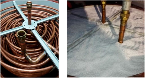
Figure 1. Schematic diagram of multi-purpose heat storage tank structure (SHARMA et al., 2009).
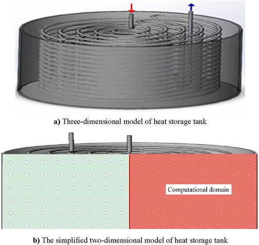
Figure 2. The computing domain of CFD. (A) Three-dimensional model of heat storage tank (B) The simplified two-dimensional model of heat storage tank.
2.2 Mathematical model
2.2.1 Phase change heat transfer model
The enthalpy method is employed in this study for solving. The enthalpy method model is mathematically represented as follows:
In the absence of convective heat exchange and internal heat sources, the energy balance Equation 1 is established by considering a given surface area (A) and control volume (V):
Equation 2 expresses the relationship between temperature and enthalpy, with
In this equation,
Assuming no internal heat sources in the PCM and considering only conductive heat exchange within the collector, Equations 3, 4 can be utilized to delineate the energy equations for the solid phase domain, liquid phase domain, and the interface between the solid and liquid phases.
This paper explores the phase change process in PCM. The enthalpy method is favored for its simplicity and high precision in calculating solid-liquid phase change processes. Hence, the numerical simulation in this paper employs the enthalpy method model to calculate the process of solid phase change.
2.2.2 Control equations
This paper’s numerical simulation focuses on the charging and discharging processes of a versatile heat storage tank to ensure the conservation of mass, energy, and momentum. Assuming laminar flow in calculations due to the weak flow of the phase change material paraffin (RT70HC) in the heat storage container. The corresponding control equations are provided in Equations 5–8:
Energy Equation
Momentum Equations
Continuity Equation
This equation employs several variables to represent various physical properties. Here,
The heat stored in the phase change material is calculated using Equation 9:
2.2.3 Melting/solidification model
In Fluent, the ‘enthalpy-porosity’ in the melting/solidification model is defined as the liquid-phase rate of a phase-change working medium, representing the degree of thermal melting. The liquid-phase rate, denoted as
If 0 <
2.3 Boundary conditions
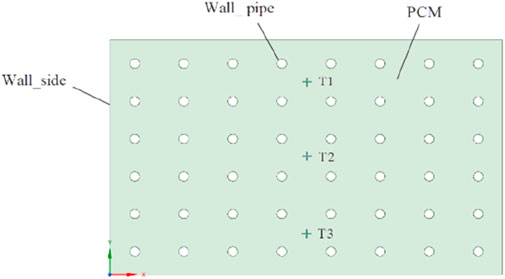
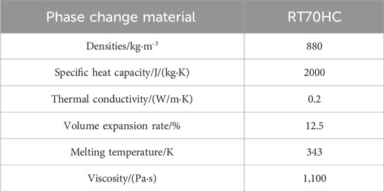
In the process of numerical computations, a quadrilateral mesh is utilized to partition the model grid, as depicted in Figure 3. Based on the mathematical model for heat transfer within the system, boundary conditions are defined for different structural boundaries within the model. The walls are made of insulating materials, and the pipe walls are maintained at a constant temperature of 350K for exchanging heat with the phase change material, specifically, the chosen phase change material is RT70HC, based on paraffin. Classified under the paraffin category in heat storage materials, RT70HC possesses a melting point of 70°C, as detailed in Table 1. It falls within the category of medium-low temperature phase change materials, with a boiling point lower than that of water. Moreover, it demonstrates a high latent heat value within this temperature range. They are employing RT70HC, a paraffin-based phase change material, for heat storage results in favorable outcomes. However, similar to numerous organic phase change materials for heat storage, paraffin-based substances encounter the obstacle of low thermal conductivity, measuring only
3 Computational verification
3.1 Mesh independence verification
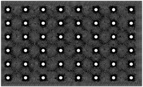
The research employed a quadrilateral mesh to partition the heat exchange model into grids, depicted in Figure 4. Due to a substantial temperature gradient in the heat exchange pipes, encryption was applied to enhance calculation accuracy. Ensuring grid independence, the researchers utilized four quadrilateral grids with grid counts of 55,000, 60,000, 65,000, and 70,000. Temperature calculation results exhibited similarity across all four grid counts, leading to the conclusion that accuracy is independent of the grid count when it's 55,000 or more. Striking a balance between computational resources and accuracy needs, the researchers chose the grid division result with a count of 65,000 for subsequent model validation.
3.2 Comparison of experimental and simulation results
Ensuring model accuracy, we compared the calculated values of three temperature monitoring points (depicted in Figure 3) with the experimental data by Kuta (Kuta, 2023). Figure 5 clearly illustrates a close correspondence between the calculated values of the three monitoring points and the experimental values. This suggests that the present calculated values align with the experimental outcomes in the referenced literature, affirming the model’s suitability for numerical simulation studies of multi-purpose thermal storage tanks.
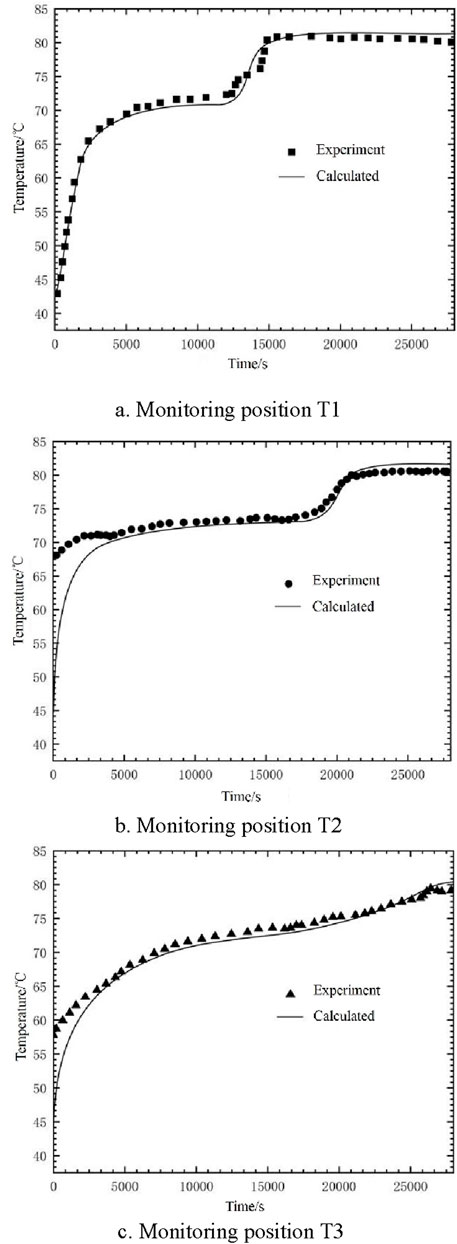
Figure 5. Comparison between calculated and experimental values of monitoring points. (A) Monitoring position T1 (B) Monitoring position T2 (C) Monitoring position T3.
4 Results
After conducting a series of experiments, a discussion was held to analyze the phase-change process during the endothermic phase, the effect of supply water temperature on this process, and the influence of heat loss. The results obtained from three tests were compared, and the most useful outcomes were selected and highlighted in the paper.
4.1 Analysis of the phase change heat transfer process in the spiral thermal storage tank
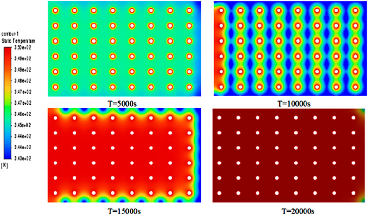
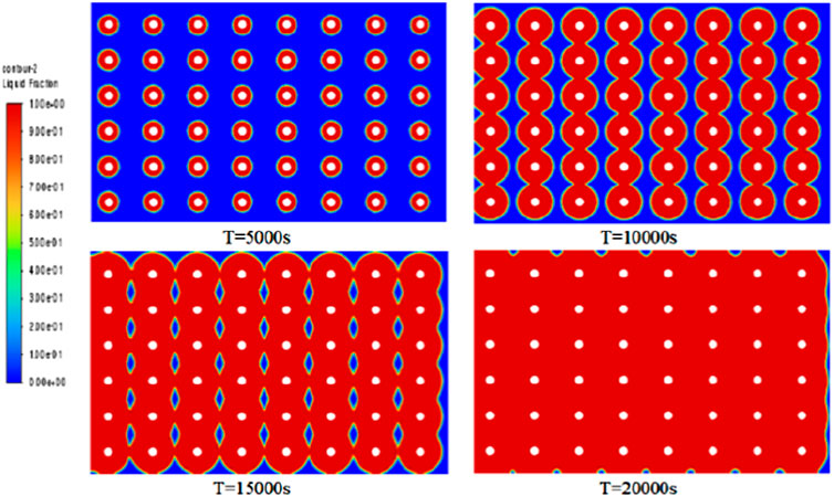
The first test experiment shows very clearly how phase changes in thermal storage depend on the water supply temperature. The maximum inlet water temperature for the first test experiment was 74.8°C, while initially the water supply temperature was assumed to be 85°C. However, this temperature was not reached in experiment 1. This would have resulted in a situation where the full phase change did not occur. As shown in Figures 6, 7, although the heat absorption process was incomplete at the experiment’s end, noticeable initial temperature changes occurred at various measurement points. However, due to insufficient heating time, heat could not fully penetrate the phase-change material’s interior. The phase-change material around the central sensor of the heat storage tank began melting slowly, approaching the initial inlet water temperature. Meanwhile, the material around the sensors near the wall of the heat storage tank melted more slowly. The temperature cloud maps suggest that the structural design of the heat storage tank contributes to lower temperatures, particularly near the tank wall, where the highest temperature of 66°C was recorded. The spiral structure of the heat storage tank is insufficient to distribute heat uniformly throughout the entire phase-change material. The melting process of the surrounding phase-change material is evident from the readings of sensors T1, T2, and T3 located at the center of the heat storage tank. With the injection of geothermal water, the temperature of the phase-change material continued to rise until reaching the melting temperature of 77°C. It should be noted that the area of the heat storage tank with the highest heat transfer efficiency is the inlet at the temperature of the water supply. However, the heat transfer process at the wall of the heat storage tank is relatively slow. As shown in Figure 8 three points were selected on the Y-axis to monitor the values of the liquid phase rate at each point along the horizontal direction, which indicates the need to optimize the design of the heat storage tank.
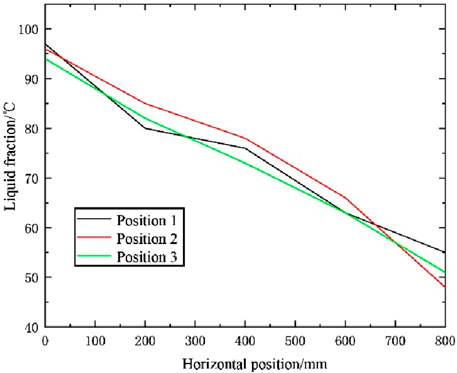
Figure 8. T1, T2, T3 internal liquid phase diagram of PCM at three points along horizontal distance.
As can be seen from the PCM temperature cloud and the liquid phase rate inside the PCM in Figures 6, 7, the heat transfer of the spiral heat storage tank is completed in about 5 h, and the heat transfer effect is basically in line with the expected results. In the initial stages of heat transfer, the melting process is relatively uniform, but in the middle stages, a distinct phenomenon emerges with faster central heat transfer and slower transfer around the wall. This observed phenomenon is closely tied to the distribution of phase-change heat transfer materials, along with the temperature and flow rate of the supplied water. Towards the conclusion of heat transfer, nearly complete melting is attained, resulting in a uniform temperature distribution that aligns with expected performance and usage standards. Examination of the temperature cloud map and internal liquid phase ratio cloud map suggests an insignificant natural convection effect, attributed to the relatively high viscosity of the phase-change material. This finding implies that the viscosity of the phase-change material is one of the most important factors affecting the significant effect of natural convection.
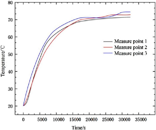
From the graphs of temperature change and liquid phase rate change, it can be observed that there is a certain inhomogeneity in the melting process of the phase change material. We monitored the changes at the central point at different time points (5,000s, 10,000s, 15,000s, and 20,000s) as shown in Figure 9. The temperature and liquid phase ratio curves exhibited repeated jumps, attributed to faster heat transfer at the central position and slower heat transfer around the periphery. This phenomenon arose due to variations in material properties, such as phase-change temperature, latent heat of phase-change, and thermal conductivity, among different materials during the phase-change process.
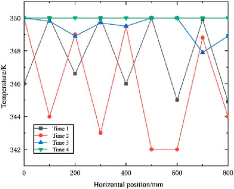
Figure 9. Internal temperature map of PCM at different times along the horizontal distance from the central point.
As temperature increase, phase-change materials begin to undergo the melting process. However, different phase-change materials have different phase-change temperatures and latent heat of phase change, so the change in liquid phase rate will vary from material to material at the same temperature. Additionally, the material’s thermal conductivity influences its heat transfer during the phase-change process, leading to varying melting rates.
The non-uniformity in the melting rate frequently leads to an uneven distribution of the liquid phase in specific areas of the material. In certain regions, the material may undergo faster melting, while in other areas, it may persist in a solid state. This disparate distribution of the liquid phase can generate thermal stress within the material, resulting in a deterioration of material performance or changes to the material structure.
Therefore, when researching and applying phase-change materials, the phenomenon of uneven melting rates should be considered, and corresponding measures should be taken to minimize its impact on material performance and application effects. For example, optimizing material composition and preparation processes can enhance phase-change performance and thermal conductivity, achieving a more uniform liquid phase distribution and a more stable phase-change process. Due to the relatively greater distance of the PCM material’s center from the heat source, less thermal energy is transferred to the central position. In contrast, the wall is closer to the heat source, allowing it to receive thermal energy more rapidly. Consequently, within the same timeframe, heat accumulation at the center position of the PCM material may be lower, resulting in a slower melting rate. Meanwhile, the wall, being closer to the heat source, accumulates more heat, leading to a faster melting rate.
Moreover, the melting rate of PCM materials is influenced by their shape and size. Inadequate design in terms of shape and size may result in uneven heat distribution, exacerbating the melting rate disparity between the center and the wall.
To address this issue, measures can be taken to optimize the performance and utilization of PCM materials. For instance, improving the design of PCM materials in terms of shape and size can better adapt them to the distribution and transfer of heat. Additionally, materials with higher thermal conductivity can be added as fillers for PCM materials to enhance their overall thermal conductivity. Simultaneously, when utilizing PCM materials, factors such as their phase-change temperature and thermal performance should be taken into account to effectively control their melting rate and thermal energy storage effect.
4.2 Impact of inlet water temperature on spiral thermal storage tank
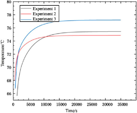
Figure 10 presents the inlet and outlet water temperatures for three tests, while Figure 11 illustrates the temperature changes recorded by three sensors positioned at the center of the thermal storage tank for each test. Analyzing variations in supply water temperatures and comparing temperature changes within the mobile thermal storage tank enables the assessment of each test’s impact on the results. Deviations in the heat source’s actual conditions from the design conditions lead to variations in supply water temperatures. Experiment 1 and Experiment 2 recorded maximum inlet water temperatures of 74.8°C and 75.4°C. Experiment 3 achieved a melting temperature closest to the design conditions, reaching a maximum of 77°C. This variance impacted the heat storage capacity of the thermal storage tank.
4.3 Impact of different phase change material properties on heat transfer process
To compare the heat transfer processes of different phase change materials, we introduced the organic phase change material RT70HC, a type of paraffin, in addition to the existing materials. Additionally, we selected the inorganic phase change material, octahydrate barium hydroxide (Ba(OH)2·8H2O), which operates at medium to low temperatures. Octahydrate barium hydroxide is an inorganic phase change material characterized by high heat capacity and excellent thermal stability, enabling it to absorb and release a substantial amount of heat. This material undergoes phase transition with temperature variations, moving from one state to another, thereby storing or releasing thermal energy.
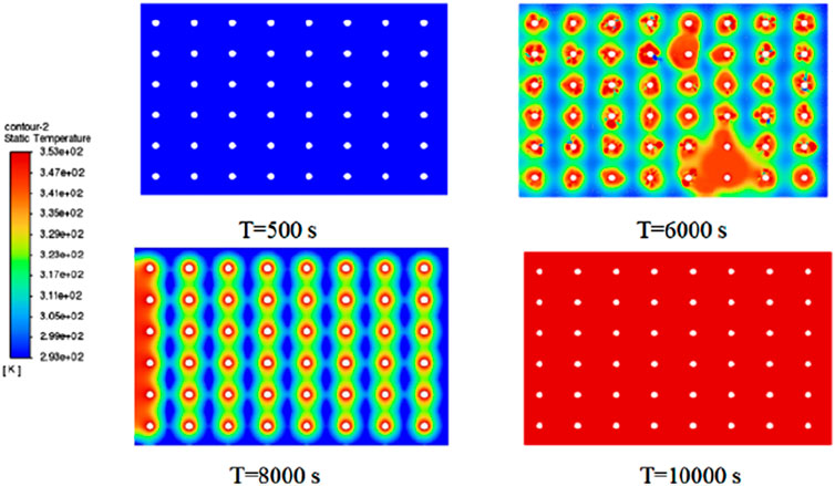
During the phase change, the heat absorbed by octahydrate barium hydroxide can be used to regulate temperature and maintain stability. This material finds widespread applications in various fields, including building energy conservation, electronic device cooling, renewable energy storage, and aerospace. In the context of building energy conservation, octahydrate barium hydroxide can be employed to manufacture insulation materials, enhancing the thermal performance of buildings. In electronic device cooling, the material can store and gradually release the heat generated during the operation of electronic devices, thereby maintaining stable device temperatures. Concerning renewable energy storage, octahydrate barium hydroxide can store surplus solar energy and release it when needed to power the grid. In summary, octahydrate barium hydroxide is a crucial inorganic phase-change material with vast application prospects. With a melting point of 77°C and significantly lower viscosity than the organic phase-change material RT70HC, assuming the introduction of hot water at 80°C into the experiment, the heat transfer process is simulated and analyzed using Fluent software, with the temperature cloud map presented in Figure 12.
From Figure 12, it can be observed that the melting process of the octahydrate barium hydroxide is faster than that of paraffin-based RT70HC, completing the melting process in only about 10,000 s. The melting speed is relatively ideal, significantly reducing the melting time and improving heat transfer efficiency. Additionally, the temperature cloud chart indicates that at the 6,000s mark, the temperature is significantly influenced by natural convection, resulting in the coupling of temperature fields. This suggests that the natural convection process should not be overlooked and is closely related to the viscosity of phase-change materials. At 8,000s into the melting process, the uniform melting heat transfer process on the outer surface of the copper tube intensifies. However, an uneven temperature field also appears, indicating that the number and arrangement of copper tube bundles affect the heat transfer process. By the 10,000s mark, the phase-change material is completely melted, concluding the heat transfer process. The heat transfer rate of the octahydrate barium hydroxide is twice that of paraffin-based RT70HC, but it is significantly affected by natural convection. Therefore, the use of different phase-change materials is a crucial factor in improving the heat storage rate. These results demonstrate that octahydrate barium hydroxide can be used for the recovery of medium to low-temperature waste heat resources, establishing a scientific foundation for the further development of low-temperature waste heat recovery methods and providing theoretical guidance for future engineering designs.
5 Conclusion
This paper focuses on a spiral tube heat storage unit filled with the phase-change material RT70HC. Fluent software is used to simulate and analyze the melting conditions of phase-change materials at different water temperatures in a spiral-moving heat storage system. To extend and shorten the heat storage effect, improvements can be made in both the structure of the heat storage tank and the chosen phase-change material. The following conclusions are drawn.
1. There are temperature variations in different parts of the heat storage tank. Specifically, the central portion exhibits more efficient heat transfer compared to the regions near the tank wall. This may be due to design issues with the heat exchanger. Improvements in the heat storage tank structure can include increasing the number of spiral coils on the wall side to enhance heat transfer along the walls. Alternatively, increasing the heat transfer area and depth by adding spiral fins can boost heat storage by 2.5%.
2. To enhance heat transfer, catalysts can be introduced into the RT70HC phase-change material. This enhances its thermal conductivity, resulting in faster and more uniform temperature conduction. Alternatively, adjusting the amount of phase-change material by increasing usage around the wall while reducing it in the central area can enhance heat transfer efficiency by 12%.
3. Using different phase-change materials can improve heat transfer rates and enhance heat storage effects. Barium Hydroxide Octahydrate, an inorganic phase-change material, can elevate heat transfer rates by nearly 50%. Despite its potential research value, it exhibits unstable properties, susceptibility to natural convection, and toxicity concerns. Hence, exploring various phase-change materials is crucial for improving the heat transfer rate of the spiral heat storage tank.
Data availability statement
The raw data supporting the conclusions of this article will be made available by the authors, without undue reservation.
Author contributions
LY Li: Writing–original draft. WX Wang: Writing–original draft. Yang YY: Investigation, Writing–review and editing. WT: Writing–review and editing.
Funding
The author(s) declare that no financial support was received for the research, authorship, and/or publication of this article.
Conflict of interest
Author WX was employed by State Grid Henan Comprehensive Energy Services Co., Ltd.
Author YY was employed by Henan Ju'an Heating Technology Co., Ltd.
The remaining authors declare that the research was conducted in the absence of any commercial or financial relationships that could be construed as a potential conflict of interest.
Publisher’s note
All claims expressed in this article are solely those of the authors and do not necessarily represent those of their affiliated organizations, or those of the publisher, the editors and the reviewers. Any product that may be evaluated in this article, or claim that may be made by its manufacturer, is not guaranteed or endorsed by the publisher.
References
Bruckner, S., Liu, S., Mir, L., Radspieler, M., Cabeza, L. F., and Lävemann, E. (2015). Industrial waste heat recovery technologies: an economic analysis of heat transformation technologies. Appl. Energy, 151: 157-67. doi:10.1016/j.apenergy.2015.01.147
DU, K., Calautit, J., Eames, P., and Wu, Y., (2021). A state-of-the-art review of the application of phase change materials (PCM) in Mobilized-Thermal Energy Storage (M-TES) for recovering low-temperature industrial waste heat (IWH) for distributed heat supply. Renew. Energy, 168: 1040-57. doi:10.1016/j.renene.2020.12.057
Fadl, M., and Eames, P. C., (2019). Numerical investigation of the influence of mushy zone parameter Amush on heat transfer characteristics in vertically and horizontally oriented thermal energy storage systems. Appl. Therm. Eng., 151: 90-9. doi:10.1016/j.applthermaleng.2019.01.102
Gao, Yuan Z., Wu, D., Dai, Z., Wang, C., Chen, B., and Zhang, X., (2023). A comprehensive review of the current status, developments, and outlooks of heat pipe photovoltaic and photovoltaic/thermal systems. Renew. Energy, 207, 539–574. doi:10.1016/j.renene.2023.03.039
Geng, L., Cui, J., Zhang, C., Yan, Y., Zhao, J., and Liu, C., (2024a). Chemistry in phase change energy storage: properties regulation on organic phase change materials by covalent bond modification, Chem. Eng. J., 495, 153359, doi:10.1016/j.cej.2024.153359
Geng, L., Tong, X., Jiang, J., Luo, K., Yan, Y., and Liu, C., (2024b). Wide temperature range phase change cold energy storage by using esterification between polyethylene glycol and lauric acid, Chem. Eng. J., 496, 154005, doi:10.1016/j.cej.2024.154005
Geng, L., Wang, J., Yang, X., Jiang, J., Li, R., Yan, Y., et al. (2024c). Synergistic enhancement of phase change materials through three-dimensional porous layered covalent triazine framework/expanded graphite composites for solar energy storage and beyond, Chem. Eng. J., 487, 150749, doi:10.1016/j.cej.2024.150749
Guo, S., Zhao, J., Wang, W., Yan, J., Jin, G., Zhang, Z., et al. (2016). Numerical study of the improvement of an indirect contact mobilized thermal energy storage container. Appl. Energy, 161: 476-86. doi:10.1016/j.apenergy.2015.10.032
Huang, R., Wu, H., and Cheng, P., (2013). A new lattice Boltzmann model for solid–liquid phase change. Int. J. Heat Mass Transf., 59: 295–301. doi:10.1016/j.ijheatmasstransfer.2012.12.027
Kang, Z., Tan, R., Zhou, W., Qin, Z., and Liu, S., (2023). Numerical simulation and optimization of a phase-change energy storage box in a modular mobile thermal energy supply system. Sustainability, 15(18): 13886, doi:10.3390/su151813886
Khudhair, A. M., and Farid, M. M., (2004). A review on energy conservation in building applications with thermal storage by latent heat using phase change materials. Energy Convers. Manag., 45(2): 263-75. doi:10.1016/s0196-8904(03)00131-6
Kuta, M., (2023). Mobilized thermal energy storage (M-TES) system design for cooperation with geothermal energy sources. Appl. Energy, 332: 120567, doi:10.1016/j.apenergy.2022.120567
Li, X., Sun, B., Sui, C., Nandi, A., Fang, H., Peng, Y., et al. (2020). Integration of daytime radiative cooling and solar heating for year-round energy saving in buildings. Nat. Commun. 11, 6101. doi:10.1038/s41467-020-19790-x
Li, H., Wang, W., Yan, J., and Dahlquist, E., (2013). Economic assessment of the mobilized thermal energy storage (M-TES) system for distributed heat supply. Appl. Energy, 104: 178-86. doi:10.1016/j.apenergy.2012.11.010
Luo, H., Li, Y., Gao, X., Meng, X., Yang, X., and Yan, J., (2023). Carbon emission prediction model of prefecture-level administrative region: a land-use-based case study of Xi'an city, China, Appl. Energy, 348, 121488, doi:10.1016/j.apenergy.2023.121488
Luo, Z., and Lu, X., (2023). Characteristics and prospect of geothermal industry in China under the “dual carbon” target. energy Geosci., 4, 4,100199, doi:10.1016/j.engeos.2023.100199
Pathak, Sudhir K., Tyagi, V.V., Chopra, K., and Sari, A., (2023.) Thermal performance and design analysis of U-tube-based vacuum tube solar collectors with and without phase change material for constant hot water generation. J. Energy Storage, 66,107352, doi:10.1016/j.est.2023.107352
Qiao, Y., Shi, K., and Liu, J. (2024). Analytical study of integrating downhole thermoelectric power generation with a coaxial borehole heat exchanger in geothermal wells. Sci. Rep. 14, 505. doi:10.1038/s41598-024-51226-0
Sharma, A., Tyagi, V. V., Chen, C. R., and Buddhi, D., (2009). Review on thermal energy storage with phase change materials and applications [J]. Renew. Sustain. Energy Rev., 13(2): 318-45. doi:10.1016/j.rser.2007.10.005
Tong, X., Zhao, J., Geng, L., Wang, Z., Qiao, W., and Liu, C. (2023). Simplicity is the ultimate sophistication: one-step forming for thermosensitive solid–solid phase change thermal energy harvesting, storage, and utilization. Chem. Eng. J. 477, 147068. doi:10.1016/j.cej.2023.147068
Xiao, J., Zou, Bo, Liu, C., Deng, L., Xing, Li, and Li, C., Carbonized loofah sponge fragments enhanced phase change thermal energy storage: preparation and thermophysical property analysis, Appl. Therm. Eng., 2024, 242, 122505, doi:10.1016/j.applthermaleng.2024.122505
Xu, Bo, Zhang, T., Wang, S., and Chen, Z., (2023). Dynamic characteristics and energy efficiency evaluation of a novel solar seasonal thermal storage - heating system. Appl. Therm. Eng., 234,121223, doi:10.1016/j.applthermaleng.2023.121223
Yang, Bo, Guo, J., Huang, X., Li, Ze, Yang, X., and Li, M.-J., Evaluation of variable rotation on enhancing thermal performance of phase change heat storage tank, Int. J. Heat Fluid Flow, 2024, 106, 109328, doi:10.1016/j.ijheatfluidflow.2024.109328
Yang, M., Moghimi, M.A., Loillier, R., Markides, C., and Kadivar, M., (2023). Design of a latent heat thermal energy storage system under simultaneous charging and discharging for solar domestic hot water applications. Appl. Energy, 336,120848, doi:10.1016/j.apenergy.2023.120848
Keywords: heat storage equipment, spiral tubes, phase change heat storage, temperature monitoring, numerical simulation
Citation: Yuna L, Xiaojun W, Yu Y and Tao W (2024) Study on the thermal storage properties of a spiral tube heat storage tank based on numerical analysis. Front. Energy Res. 12:1458591. doi: 10.3389/fenrg.2024.1458591
Received: 02 July 2024; Accepted: 04 September 2024;
Published: 25 October 2024.
Edited by:
Changhui Liu, China University of Mining and Technology, ChinaReviewed by:
Min Xu, Institute of Engineering Thermophysics, Chinese Academy of Sciences (CAS), ChinaXiaohu Yang, Xi’an Jiaotong University, China
Copyright © 2024 Yuna, Xiaojun, Yu and Tao. This is an open-access article distributed under the terms of the Creative Commons Attribution License (CC BY). The use, distribution or reproduction in other forums is permitted, provided the original author(s) and the copyright owner(s) are credited and that the original publication in this journal is cited, in accordance with accepted academic practice. No use, distribution or reproduction is permitted which does not comply with these terms.
*Correspondence: Wang Tao, d2FuZ3Rhb0B6enVsaS5lZHUuY24=
 Li Yuna1
 Wang Tao