 Qize He
 Fanyue Kong
 Rong Sun3
- 1Shanghi Fire Research Institute of MEM, Shanghai, China
- 2School of Energy and Power Engineering, University of Shanghai for Science and Technology, Shanghai, China
- 3Research Institute, State Grid Jiangsu Electric Power Co., Ltd., Nanjing, China
With the advancement of Fuel Cell Vehicles (FCVs), detecting hydrogen leaks is critically important in facilities such as hydrogen refilling stations. Despite its significance, the dynamic response performance of hydrogen sensors in confined spaces, particularly under ceilings, has not been comprehensively assessed. This study utilizes a catalytic combustion hydrogen sensor to monitor hydrogen leaks in a confined area. It examines the effects of leak size and placement height on the distribution of hydrogen concentrations beneath the ceiling. Results indicate that hydrogen concentration rapidly decreases within a 0.5–1.0 m range below the ceiling and declines more gradually from 1.0 to 2.0 m. The study further explores the attenuation pattern of hydrogen concentration radially from the hydrogen jet under the ceiling. By normalizing the radius and concentration, it was determined that the distribution conforms to a Gaussian model, akin to that observed in open space jet flows. Utilizing this Gaussian assumption, the model is refined by incorporating an impact reflux term, thereby enhancing the accuracy of the predictive formula.
1 Introduction
Driven by environmental emission standards and energy crises, hydrogen has emerged as a zero-carbon, clean energy source (Zou et al., 2023). In recent years, Fuel Cell Vehicles (FCVs) have become a significant focus for future automotive industry development, with hydrogen refueling stations playing a crucial role in integrating hydrogen energy technologies into daily transportation (Miao et al., 2024). Despite these advances, hydrogen’s low density results in rapid dispersion during leaks, presenting considerable safety hazards, such as fires and explosions, during storage, transport, and usage. These issues impede the global-scale adoption of hydrogen energy applications and the development of related infrastructure (Wang et al., 2022).
During the storage and transportation of hydrogen, the high internal energy associated with maintaining it under high pressure presents a risk (Li Y. et al., 2023). Hydrogen leaks may occur due to pipeline damage. To quickly detect these leaks and avert potential accidents, hydrogen sensors are strategically placed to continuously monitor and mitigate risks (Li J. et al., 2023). Both experimental and numerical simulation tools are extensively utilized to examine the distribution characteristics of hydrogen leaks under various conditions. Xu et al. (2024) conducted experimental and numerical research on hydrogen leakage in spaces with significant aspect ratios, developing a method for calculating hydrogen-weighted concentrations based on diffusion characteristics to set warning thresholds or devise emergency strategies. Takeno et al. (2007) explored the dynamics of hydrogen diffusion and explosion under scenarios where a pressurized pipeline is abruptly exposed to ambient conditions, conducting tests that varied in leak diameter, initial pressure, duration, and ignition location. Sommersel et al. (2009) applied experimental techniques to investigate hydrogen diffusion and combustion in narrow channels, observing flame propagation through high-speed videography with hydrogen flow rates between 1.8 and 75 dm³/min. Bratland et al. (2021) performed experiments on hydrogen explosions in the same channels to analyze the dynamic structural response and estimate potential structural damages. Lucas et al. (2021); Lucas et al. (2023) used CFD method to study hydrogen release and combustion in both ventilation enclosures and large-scale practical scenarios. Additionally, in a separate study, Makarov et al. (2009) conducted numerical simulations of hydrogen explosions at hydrogen refueling stations, achieving a reasonable consistency with experimental outcomes.
Numerical simulation methods are widely employed for simulating hydrogen leakage due to their capability to capture a broad spectrum of fluid flow states, flexibility in setting boundaries, and the repeatability of computational scenarios. These methods primarily rely on integral models or CFD to achieve relatively precise jet distribution models (He et al., 2024; Chen et al., 2023; Liu and He, 2024; Xie et al., 2024). Moen et al. (2019) utilized the simulation tool FLACS for CFD simulations of upward vertical hydrogen buoyant jets impinging on a solid wall. The concentration distribution results revealed a distinctive axial hyperbolic decay and radial Gaussian distribution. Li et al. (2019) conducted simulations of hydrogen jets issuing from rectangular nozzles with varying aspect ratios using CFD tools. The findings suggest that, apart from the short-axis plane, the nozzle’s profile displays the maximum mass fraction and velocity away from the central axis, with the distributions along the long-axis and radial directions aligning with those from conventional nozzle jets. Giannissi et al. (2021) applied the CFD code ADREA-HF and integral models to simulate axial and radial hydrogen mass fractions in low-temperature hydrogen jetting. Their results were also consistent with the corresponding decay models in both directions.
Turbulence presents challenges in modeling hydrogen leakage, particularly in jet releases where accurately replicating the complex flow dynamics is challenging via numerical simulations alone. As a result, it becomes essential to qualitatively analyze the hydrogen concentration field through sampling experiments (Faye et al., 2022; Tian et al., 2024; Bi et al., 2023; Gao et al., 2024). Shu et al. (2021) proposed a simplified model based on theories of axial hyperbolic decay and radial Gaussian distribution to rapidly predict the concentration distribution in hydrogen jet releases. This model was validated through the establishment of a concentration sensor array that measured the concentrations in practice, confirming the model’s accuracy in both radial and axial directions. Gong et al. (2021) employed concentration sensors to explore the concentration distribution and diffusion characteristics of low-temperature hydrogen when suddenly released from energy storage systems into the ambient air. The experiments revealed that the concentration distribution of low-temperature hydrogen jets adheres to a hyperbolic decay pattern, with concentration along the central axis increasing as hydrogen temperature decreases. Additionally, Li et al. (2024) investigated jet fires initiated by leaks from high-pressure hydrogen storage bottles, deriving empirical formulas for flame length relative to leak pressure and aperture size under varying ambient wind speeds through data fitting.
While extensive research has focused on the dispersion characteristics of hydrogen leakage in various environments, most studies have concentrated on open spaces. There is a notable lack of reliable data concerning hydrogen leak diffusion in confined spaces, such as ceilings. Additionally, although previous studies on free jets have identified specific patterns, research on confined spaces typically provides a general overview of spatial concentration distribution patterns based on parameters, without detailed empirical formulas.
Based on the analysis above, this study developed an experimental system to investigate hydrogen leakage diffusion in confined spaces. The system features a hydrogen release mechanism with adjustable pressure. Key parameters such as leak pressure, nozzle diameter, and initial nozzle height were set for different operating conditions. Data collection utilized outdoor-suitable hydrogen sensors to study the diffusion mechanisms of hydrogen leaks near the ceiling in confined spaces. It is important to note that in previous experiments, the distance of measurement points from the leak source was less than 100 times the leak source diameter. In contrast, in this study, the distance reached up to 104 times the diameter of the leak source, yielding results that more accurately reflect the actual distribution patterns of hydrogen leakage concentration. Mechanisms including self-similarity, axial concentration distribution, and radial concentration distribution are learnt from the experiments. Ultimately, empirical formulas describing the concentration distribution patterns of hydrogen leakage jets were derived.
2 Experimental setup
2.1 Experimental model
Experiments were designed to investigate the spatial distribution patterns of hydrogen diffusion in a confined space with dimensions of 6.0 m (L) × 4.0 m (W) × 3.0 m (H), depicted in Figure 1. The perimeter of the space is covered by tarpaulin to shield the hydrogen flow from environmental wind. The hydrogen sensors is fixed at a specific location below the ceiling, and the hydrogen leakage nozzle is mounted on a telescopic frame to allow for height adjustments. The positioning and elevation of the hydrogen sensor can be modified by adjusting the telescopic frame.
Figure 1. Experimental site layout diagram.
2.2 Hydrogen release system
In order to simulate hydrogen leakage diffusion in confined spaces, a hydrogen release system with adjustable release pressure was designed. Figure 2 illustrates the specific structure of the system. The main components include an explosion-proof distribution valve, release control software, pipelines, and carbon fiber-wrapped hydrogen storage cylinders. Figure 3 depicts the structural diagram of the gas control logic. This system reduces the gas source pressure via the pressure relief valve and maintains stable pressure control within the high-pressure cylinders through PID regulation between the solenoid valve and the high-pressure sensor, thus facilitating stable pressure release. The pressure for hydrogen release can be set as needed. The entire process from nitrogen displacement to hydrogen release is automatically controlled to ensure the safety, reliability, and stability of the experimental process.
Figure 2. Diagram of the hydrogen release system.
Figure 3. The variation trend of hydrogen volume fraction in the horizontal direction.
2.3 Hydrogen sensor
Specialized hydrogen sensor is selected based on factors such as accuracy, response speed, measurement range, cost-effectiveness, and sensitivity to environmental influences. In this experiment, the HNC-H2-2 hydrogen sensor was chosen. This sensor, designed based on the principles of catalytic combustion, provides several advantages such as resistance to thermal shock, impact from high-concentration hydrogen, silane poisoning, and exhibits robust stability. The chosen sensor encompasses a measurement range of 0.25%–4%, maintaining an accuracy within ±10% FS. Specific parameters are detailed in Table 1.
Table 1. Hydrogen sensor parameters.
2.4 Test conditions
The leakage pressure is 4 MPa, with leak nozzle diameters of 0.16 mm in all the tests. The height of the leakage point is set at 1.5, 2.0 and 2.5 m. The sensor’s projection directly below on the ground serves as the origin. The horizontal distance between the leakage nozzle and sensor varies from 0 to 2 m. Specific experimental conditions are outlined in Table 2.
Table 2. Experimental working condition setting.
3 Results and discussions
3.1 Self similarity research
The density of a turbulent axisymmetric jet exhibits self-similarity (Chen and Rodi, 1980). In the study of hydrogen leakage, self similarity is reflected in the gas concentration distribution formed during the leakage process. At different time and spatial scales, the diffusion patterns of hydrogen may exhibit similar shapes, reflecting similar characteristics in concentration distribution at different heights or distances. However, true self-similarity is unattainable when the jet’s density differs from that of the surrounding fluid. Thring and Newby (1953) noted that the jet’s density gradually aligns with that of the ambient fluid due to the entrainment of ambient air, particularly at a substantial distance from the jet outlet. In regions remote from the jet centerline, provided the momentum flux attributable to buoyancy is significantly less than that produced by the initial velocity, the jet behaves similarly to a jet of constant density.
Figure 3 shows the variation trend of hydrogen concentration at the sensor coordinates x = y and x = 0, y = i points with a leakage nozzle diameter of 0.16 mm at source heights of 2.0 and 2.5 m. Among them, the projection of the sensor perpendicular to the ground is taken as the origin, and fixed points are set in units of 0.5 m in the vertical and horizontal directions. The maximum value in the horizontal direction (x) is taken as 2.0 m, and the maximum value in the vertical direction (y) is taken as 2.5. Where x = y represents the trend of leakage concentration along the diagonal, x = 0 refers to the vertical projection point of the leakage source, and y = i represents the hydrogen concentration value at a fixed height (i) in the vertical direction. It can be observed that the trend of hydrogen volume fraction remains consistent under both conditions, leading to the derivation of the empirical formula as Equation 1:
The symbol c denotes the volume fraction of hydrogen gas which is the function of radius r. The R2 value of the fitting results is 0.98, which suggests that the circular nozzle hydrogen leak jet maintains self-similarity in confined spaces. This is reasonable since the nozzle diameter was merely 0.16 mm in our experiments, with the measuring point’s height significantly exceeding the nozzle diameter. It also shows the same rule with Hinze’s research, which indicated that beyond a distance of 10 d (inlet diameter) from the leak source, the jet transitions to turbulence and undergoes conical expansion, approaching self-similarity in flow behavior (Hinze, 1975).
3.2 Axial distribution of hydrogen concentration
From the analysis above, the release of hydrogen gas from a circular nozzle in confined spaces demonstrates self-similarity. Therefore, examining radial concentration decay patterns at the ceiling necessitates analysis along specific radial axis.
Figure 4 depicts the experimental coordinates of the radial axis at a horizontal distance of 0 m below the ceiling for a leak source at various axial distances. In this setup, the z-axis is defined as the vertical direction from the center of the leak opening, while the r-axis is defined as the horizontal direction beneath the ceiling. The hydrogen gas sensor is fixed below the ceiling, and varying the height of the leak nozzle achieves different axial coordinates of the ceiling within the hydrogen jet. The measurement points are located where the projection of the leak opening intersects the ceiling, aiming to investigate the hydrogen gas concentration distribution pattern along the jet’s centerline at the ceiling.
Figure 4. Coordinate diagram.
Figure 5 illustrates the trend in hydrogen gas concentration at various ceiling measurement points at different heights (r = 0, z = 0.5, 1.0, 1.5, 2.5). The graph indicates that hydrogen gas concentration decreases with increasing height. Specifically, between 0.5 < z < 1.0, the concentration declines rapidly, followed by a more gradual reduction. Initially, the hydrogen jet flow is predominantly propelled by its initial momentum. Given the relatively low ceiling height, the jet reaches the measurement points swiftly under momentum influence, leading to elevated readings from the hydrogen gas sensor. As ceiling height increases, the axial distance of the jet’s motion extends, diminishing the influence of the initial momentum while enhancing the buoyancy force, which alters the direction of the hydrogen jet movement. Consequently, by the time the jet front arrives at the measurement points, the hydrogen jet has begun to disperse outward due to buoyancy. Therefore, as height increases, the concentration at centerline ceiling measurement points progressively decreases, and the rate of decrease lessens with increasing height.

Figure 5. Hydrogen axial concentration attenuation.
From the graph, it can be seen that the reciprocal of the average concentration at each measurement point shows a linear trend, with its relationship to the axial distance z being as Equation 2:
For hydrogen free jets, Hinze (1975) and Field et al. (1967) have provided a general formula for the axial decay of average concentration as Equation 3:
In this formula,
Figure 6. Normalized fitting of the average concentration.
3.3 Radial distribution of hydrogen concentration
In order to investigate the radial-axial distribution law of hydrogen concentration in a leakage jet under confined space. Measurement sensors are placed in the horizontal directions at r = 0, 0.5, 1.0, 1.5, 2.0, 2.5 m. The detailed testing conditions are presented in Table 3.
Table 3. Radial concentration distribution working condition.
Figure 7 illustrates the variation in hydrogen concentration along the radial axis at different ceiling heights, with the concentration values representing time-averaged measurements. In test 1, the elevated ceiling height causes the hydrogen sensors at distant horizontal measurement points to show no significant response, indicating that the interference from ambient wind cannot be completely eliminated.
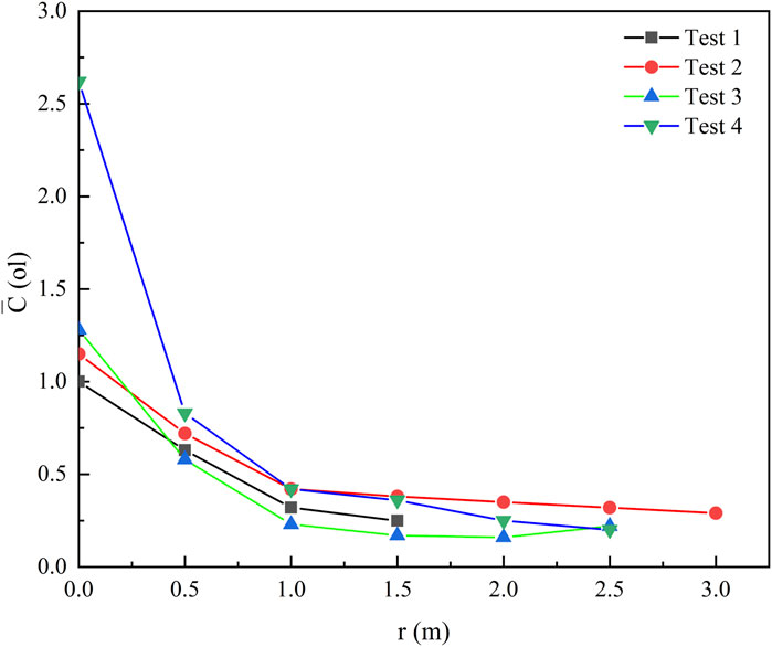
Figure 7. Hydrogen concentration variation in the vertical and horizontal directions.
It is evident that the trend of hydrogen concentration changes similarly at different ceiling heights, with concentrations decreasing as the horizontal distance increases. At r = 0, where the measurement point is directly on the center axis of the jet, the hydrogen concentration is significantly higher compared to other points, particularly under the fourth working condition (z = 0.5). This occurs because, in the absence of ambient wind, the hydrogen flows vertically upward before dispersing laterally upon reaching the ceiling. Consequently, at r = 0, the hydrogen concentration is invariably highest under all working conditions. Between 0 < r< 1.0, the decline in hydrogen concentration is relatively steep, thereafter tapering off. In the ceiling jet mode of hydrogen flow, areas near the central axis exhibit a sharp decrease in concentration as the hydrogen swiftly disperses outward. Beyond the radial axis 1.0 < r < 3.0, hydrogen sensors capture dispersed hydrogen at the measurement point, propelled by buoyancy forces that dominate over momentum forces in directing the hydrogen jet. Therefore, at locations distant from the radial axis, the decrease in hydrogen called is gradual across all working conditions.
Based on hydrogen concentration data obtained from sensors, a quantitative analysis was conducted to explore the decay law of hydrogen concentration along radial and axial directions. For axial measurements, the jet width (b) normalizes the axial ceiling height (z), and the reciprocal of the hydrogen volume fraction is plotted on the vertical axis to present the experimental results under various operating conditions, as illustrated in Figure 8.
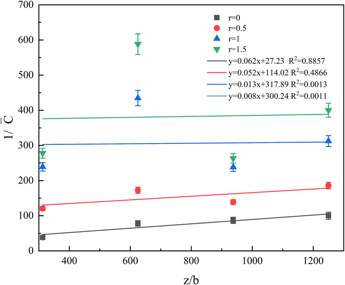
Figure 8. Concentration distribution in the radial direction.
The concentration distribution law and fitting curve across different radii in the axial direction are depicted. The reciprocal of the mass fraction is linearly fitted to the dimensionless axial distance using the least squares method. The results indicate that the concentration at the central axis (r = 0) exhibits a linear decrease with the increase in baffle height, and the axial diffusion rate is 0.0622, in accordance with Equation 2. However, as the radial position varies, the linear correlation of the attenuation along the axial direction weakens with increasing distance from the central axis. Additionally, disturbances become more pronounced with increasing radial distance, decreasing the prediction accuracy of the fitted curve for its concentration point.
In the radial direction, the radial distance r is normalized by the jet width b, and experimental measurements under various operating conditions are depicted. Figure 9 illustrates the concentration distribution pattern and the corresponding fitting curve at various baffle heights in the radial direction. When the baffle height is held constant, the hydrogen concentration decreases progressively with increasing radius.
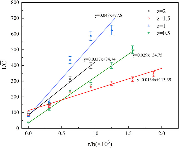
Figure 9. Concentration distribution in the axial direction.
The data was then fitted with the vertical axis represented as (1/
Different radial diffusion fitting functions yield varying diffusion distances when the gas concentration diminishes to half of the central point concentration (r0.5) along the radial direction. Figure 10 displays the central point concentrations and corresponding r0.5 values for various z values. As z increases, r0.5 initially rises and then declines. This trend is observed because an increase in the distance between the jet outlet and the baffle expands the diffusion range of the jet flow. However, under the baffle’s influence, the jet’s momentum reduces at its endpoint, causing a rapid concentration decrease upon impact with the baffle. Consequently, at z = 2.0, r0.5 decreases.

Figure 10. Central and r0.5 concentration at different z-values.
Based on varying r0.5 values, the dimensionless radial diffusion distance (r/r0.5) serves as the horizontal axis, while the dimensionless concentration (C/Cel), with Cel representing the center point concentration, is plotted on the vertical axis.
The concentration distribution at any downstream position in a self-similar axisymmetric jet approximates a Gaussian distribution (Field et al., 1967; Rafael Ortiz et al., 2018; Agrawal and Prasad, 2003) as Equation 5.
Schefer et al. (2008) proposed the corresponding flow direction concentration formula for hydrogen free jet as Equation 6:
After coefficient changes, the above formula can be rewritten as Equation 7:
Based on experimental data, distribution curves for various measurement points were plotted. Figure 11 illustrates the radial dimensionless mass fraction distribution of the hydrogen jet. The distribution of all data points closely aligns with the same Gaussian curve, further demonstrating the self-similarity in the radial concentration distribution of the jet gas. The governing equation is derived as Equation 8:
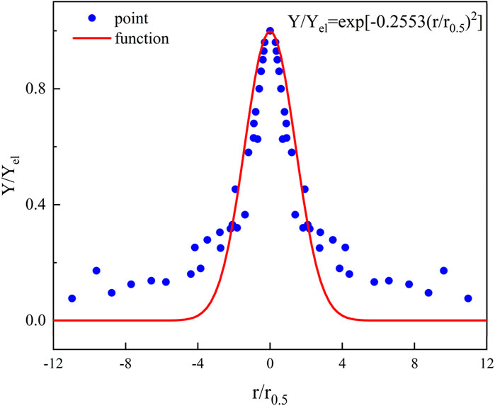
Figure 11. Radial dimensionless mass fraction distribution of hydrogen jet.
Compared to the Gaussian distribution formula previously proposed, the fitting results presented in this paper differ only in coefficient terms. This discrepancy is attributable to the operating conditions employed in the experiment. Prior research primarily examined the distribution of hydrogen concentration in the downstream free jet field of an open space, whereas this study investigates an axisymmetric jet within a confined space, focusing on the concentration distribution at the space’s apex. Notably, in earlier experiments, the distance from the measurement points to the leakage source was less than 100 d (diameter of the leakage source), and in this study, the distance extended to 104 d. The findings more accurately reflect the concentration distribution law of hydrogen leakage at actual hydrogen refueling stations.
The consistency of hydrogen concentration distribution under open space free jet conditions is relatively low in confined spaces. In an open space, hydrogen undergoes free expansion driven by initial momentum, whereas in confined spaces, the jet is constrained by fixed boundaries, affecting the expansion dynamics. When the jet impacts the ceiling, it generates a reflux, which in turn creates a symmetrical flow distribution around the central axis. Consequently, an additional Gaussian distribution is introduced to model the reflux fluid. The fitting results are displayed in Figure 12.
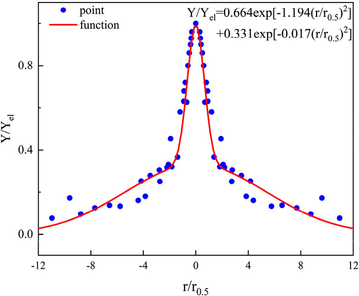
Figure 12. Optimizing Gaussian distribution fitting results of hydrogen jet.
The fitting formula is Equation 9:
This formula accounts for the influence of jet mainstream and ceiling impact reflux on spatial concentration distribution and enhances the modeling of flow field disturbances during radial diffusion. It is more accurate and representative of the actual distribution in confined ceiling spaces compared to prior empirical formulations.
4 Concluding
This paper designs a hydrogen leakage experimental platform following the setup in hydrogen refueling stations. The concentration distribution patterns of the jet following a hydrogen leak under the roof structure of the refueling station are mainly investigated. Based on the experimental results, the concentration distribution law of hydrogen leakage jet in the confined space of the ceiling was summarized and an empirical formula was fitted, providing a reference basis for the prevention and control of future hydrogen refueling stations and other infrastructure. The conclusions are as follows:
(1) The variable-density turbulent axisymmetric jet continues to exhibit self-similarity. Concentration measurements taken below the roof (z = r) and at various radial positions (z = 0, r = 0.5, 1.0, 1.5, 2.0, 2.5) revealed consistent hydrogen concentration attenuation trends under these conditions. Data analysis from both experiments demonstrated a high R2 value of 0.98, suggesting that beyond a distance equivalent to ten times the diameter of the leakage point, the hydrogen jet maintains self-similarity without the need to account for variable-density effects.
(2) Qualitative analysis of the attenuation law of hydrogen concentration at the top of the spatial centerline of the confined space hydrogen leakage jet was conducted. By standardizing the axial distance z using a virtual origin z0 and the leak orifice diameter d, the relationships between the reciprocal of the average concentration and the standardized distance were fitted.
(3) Qualitative analysis was conducted on the attenuation law of hydrogen concentration at the top of a confined space in the radial direction of a hydrogen leakage jet. By normalizing the radial distance (r) with r0.5 and the concentration at each point (C) with the central point concentration (Cel), it was observed that the concentration distribution at each measurement point in the space adheres to a Gaussian distribution. This was compared with the concentration empirical formula for axisymmetric jets in open space previously studied by researchers, and the reasons for the discrepancies were analyzed. Furthermore, taking into account the differences in jet flow between confined and open spaces, the fitting formula was optimized by incorporating an impact reflux term, resulting in a more accurate gas concentration fitting distribution law.
Data availability statement
The raw data supporting the conclusions of this article will be made available by the authors, without undue reservation.
Author contributions
QH: Writing–original draft, Writing–review and editing. FK: Data curation, Formal Analysis, Writing–review and editing. RL: Data curation, Formal Analysis, Visualization, Writing–review and editing. JY: Supervision, Writing–review and editing.
Funding
The author(s) declare that financial support was received for the research, authorship, and/or publication of this article. The authors are grateful for National project funding for Key R&D program under Grant No. 2023YFC3009900 and Shanghai Sailing Program under Grant No. 22FY1452500.
Conflict of interest
Author RS was employed by State Grid Jiangsu Electric Power Co., Ltd.
The remaining authors declare that the research was conducted in the absence of any commercial or financial relationships that could be construed as a potential conflict of interest.
Publisher’s note
All claims expressed in this article are solely those of the authors and do not necessarily represent those of their affiliated organizations, or those of the publisher, the editors and the reviewers. Any product that may be evaluated in this article, or claim that may be made by its manufacturer, is not guaranteed or endorsed by the publisher.
References
Agrawal, A., and Prasad, A. K. (2003). Integral solution for the mean flow profiles of turbulent jets, plumes, and wakes. Fluids Eng. 125, 813–822. doi:10.1115/1.1603303
Bi, Yo, Wu, Q., Wang, S., Shi, J., Cong, H., Ye, L., et al. (2023). Hydrogen leakage location prediction at hydrogen refueling stations based on deep learning. Energy 284, 129361. doi:10.1016/j.energy.2023.129361
Bratland, M., Bjerketvedt, D., and Vaagsaether, K. (2021). Structural response analysis of explosions in hydrogen-air mixtures in tunnel-like geometries. Eng. Struct. 231, 111844. doi:10.1016/j.engstruct.2020.111844
Chen, C. J., and Rodi, W. (1980). Vertical turbulent buoyant jets – a review of experimental data. New York: Pergamon Press.
Chen, G., Li, C., Lu, L., Li, P., Ye, S., Wang, T., et al. (2023). Promoting the discoloration of PdO in low concentration H2 by using PdAu bimetallic catalyst for eye-readable hydrogen leakage detection. Sensors Actuators B Chem. 393, 134199. doi:10.1016/j.snb.2023.134199
Faye, O., Szpunar, J., and Eduok, U. (2022). A critical review on the current technologies for the generation, storage, and transportation of hydrogen. Int. J. Hydrogen Energy 47, 13771–13802. doi:10.1016/j.ijhydene.2022.02.112
Field, M. A., Gill, D. W., Morgan, B., et al. (1967). Combustion of pulverised coal. British coal utilisatwn research association. England: Leatherhead.
Gao, K., Creasy, N. M., Huang, L., and Gross, M. R. (2024). Underground hydrogen storage leakage detection and characterization based on machine learning of sparse seismic data. Int. J. Hydrogen Energy 61, 137–161. doi:10.1016/j.ijhydene.2024.02.296
Giannissi, S. G., Venetsanos, A. G., and Hecht, E. S. (2021). Numerical predictions of cryogenic hydrogen vertical jets. Int. J. Hydrogen Energy 46, 12566–12576. doi:10.1016/j.ijhydene.2020.08.021
Gong, L., Yang, S., Han, Y., Jin, K., Lu, L., Gao, Y., et al. (2021). Experimental investigation on the dispersion characteristics and concentration distribution of unignited low-temperature hydrogen release. Process Saf. Environ. Prot. 160, 676–682. doi:10.1016/j.psep.2022.02.055
He, X., Kong, D., Yu, X., Ping, P., Wang, G., Peng, R., et al. (2024). Prediction model for the evolution of hydrogen concentration under leakage in hydrogen refueling station using deep neural networks. Int. J. Hydrogen Energy 51, 702–712. doi:10.1016/j.ijhydene.2022.12.102
Li, J., Tian, Z., Yang, Q., Feng, L., Su, H., and Lan, H. (2023). A new visual approach with the concentration calibration method for the hydrogen leakage and distribution research. Fuel 346, 128132. doi:10.1016/j.fuel.2023.128132
Li, X., Chen, Q., Chen, M., He, Q., Christopher, D. M., Cheng, X., et al. (2019). Modeling of underexpanded hydrogen jets through square and rectangular slot nozzles. Int. J. Hydrogen Energy 44, 6353–6365. doi:10.1016/j.ijhydene.2019.01.079
Li, X., Hao, Y., Wu, F., Xing, Z., Zhuang, S., and Wang, X. (2024). Numerical simulation of leakage jet flame hazard of high-pressure hydrogen storage bottle in open space. Int. J. Hydrogen Energy 62, 706–721. doi:10.1016/j.ijhydene.2024.03.088
Li, Y., Wang, Z., Shi, X., and Fan, R. (2023). Safety analysis of hydrogen leakage accident with a mobile hydrogen refueling station. Process Saf. Environ. Prot. 171, 619–629. doi:10.1016/j.psep.2023.01.051
Liu, S., and He, R. (2024). Decision-level fusion detection method of hydrogen leakage in hydrogen supply system of fuel cell truck. Fuel 367, 131455. doi:10.1016/j.fuel.2024.131455
Lucas, M., Atanga, G., Hisken, H., Mauri, L., and Skjold, T. (2021). Simulating vented hydrogen deflagrations: improved modelling in the CFD tool FLACS- hydrogen. Int. J. Hydrogen Energy 46, 12464–12473. doi:10.1016/j.ijhydene.2020.09.073
Lucas, M., Hisken, H., Skjold, T., Arntzen, B. J., and van Wingerden, K. (2023). CFD modelling of hydrogen and hydrogen-methane explosions - analysis of varying concentration and reduced oxygen atmospheres. J. Loss Prev. Process. Ind. 83, 105012. doi:10.1016/j.jlp.2023.105012
Makarov, D., Verbecke, F., Molkov, V., Roe, O., Skotenne, M., Kotchourko, A., et al. (2009). An inter-comparison exercise on CFD modelcapabilities to predict a hydrogen explosion in a simulated vehicle refuellingenvironment. Int. J. Hydrogen Energy 34, 2800–2814. doi:10.1016/j.ijhydene.2008.12.067
Miao, Y., Jia, C., Hua, Y., Zhang, X., Sun, L., Huang, G., et al. (2024). Quantification of concentration characteristics of hydrogen leakage in electro-hydrogen coupled system with different obstacles via Background Oriented Schlieren. J. Energy Storage 83, 110764. doi:10.1016/j.est.2024.110764
Moen, A., Mauri, L., and Narasimhamurthy, V. D. (2019). Comparison of k-ε models in gaseous release and dispersion simulations using the CFD code FLACS. Process Saf. Environ. Prot. 130, 306–316. doi:10.1016/j.psep.2019.08.016
Rafael Ortiz, C., Eveline, W., William, B., Bonato, C., Hartmann, K., and Schmidt, K. (2018). Test methodologies for hydrogen sensor performance assessment: chamber vs. flow-through test apparatus. Int. J. Hydrogen Energy 43, 21149–21160. doi:10.1016/j.ijhydene.2018.09.107
Schefer, R., Houf, W., and Williams, T. (2008). Investigation of small-scale unintended releases of hydrogen: momentum-dominated regime. Int. J. Hydrogen Energy 33, 6373–6384. doi:10.1016/j.ijhydene.2008.05.041
Shu, Z., Liang, W., Zheng, X., Lei, G., Cao, P., Dai, W., et al. (2021). Dispersion characteristics of hydrogen leakage: comparing the prediction model with the experiment. Energy 236, 121420. doi:10.1016/j.energy.2021.121420
Sommersel, O. K., Bjerketvedt, D., Vaagsaether, K., and Fannelop, T. (2009). Experiments with release and ignition of hydrogen gas in a 3m long channel. Int. J. Hydrogen Energy 34, 5869–5874. doi:10.1016/j.ijhydene.2009.02.058
Takeno, K., Okabayashi, K., Kouchi, A., Nonaka, T., Hashiguchi, K., and Chitose, K. (2007). Dispersion and explosion field tests for 40MPa pressurized hydrogen. Int. J. Hydrogen Energy 32, 2144–2153. doi:10.1016/j.ijhydene.2007.04.018
Thring, M. W., and Newby, M. P. (1953). Combustion length of enclosed turbulent jet flames. Fourth Symposium Int. Combust. 52, 789–796. doi:10.1016/s0082-0784(53)80103-7
Tian, Y., Qin, C., Yang, Z., and Hao, D. (2024). Numerical simulation study on the leakage and diffusion characteristics of high-pressure hydrogen gas in different spatial scenes. Int. J. Hydrogen Energy 50, 1335–1349. doi:10.1016/j.ijhydene.2023.10.253
Wang, T., Yang, F., Hu, Q., Hu, S., Li, Y., and Ouyang, M. (2022). Experimental and simulation research on hydrogen leakage of double ferrule joints. Process Saf. Environ. Prot. 60, 839–846. doi:10.1016/j.psep.2022.02.056
Xie, L., Yuan, F., Long, R., Liu, Z., and Liu, W. (2024). Accelerating flammable gas cloud dissipation in hydrogen leakage during refilling hydrogen-powered vehicles via employing canopy fans. Int. J. Hydrogen Energy. doi:10.1016/j.ijhydene.2024.03.117
Xu, Q., Chen, G., Xie, M., Li, X., Zhao, Y., Su, S., et al. (2024). Experimental and numerical studies on hydrogen leakage and dispersion evolution characteristics in space with large aspect ratios. J. Clean. Prod. 438, 140467. doi:10.1016/j.jclepro.2023.140467
Keywords: hydrogen leakage, confined space, concentration distribution pattern, hydrogen detection, FCV safety
Citation: He Q, Kong F, Sun R, Li R, Yang J and Min Q (2024) Experimental study on dynamic response performance of hydrogen sensor in confined space under ceiling. Front. Energy Res. 12:1456316. doi: 10.3389/fenrg.2024.1456316
Received: 17 July 2024; Accepted: 04 October 2024;
Published: 16 October 2024.
Edited by:
Haotian Liu, University of California, Los Angeles, United StatesReviewed by:
Zhi Yang, Rice University, United StatesRamchandra Gawas, Berkeley Lab (DOE), United States
Copyright © 2024 He, Kong, Sun, Li, Yang and Min. This is an open-access article distributed under the terms of the Creative Commons Attribution License (CC BY). The use, distribution or reproduction in other forums is permitted, provided the original author(s) and the copyright owner(s) are credited and that the original publication in this journal is cited, in accordance with accepted academic practice. No use, distribution or reproduction is permitted which does not comply with these terms.
*Correspondence: Qize He, aGVxaXplQHNoZnJpLmNu; Juntao Yang, eWFuZ2p1bnRhb0BzaGZyaS5jbg==