- 1Department of Electrical Engineering, National Institute of Technology Rourkela, Rourkela, India
- 2Department of Electrical Engineering, National Institute of Technology Durgapur, Durgapur, India
- 3Department of Electrical Engineering, Abacus Institute of Engineering and Management, Hooghly, India
- 4Department of Electrical Engineering, Ghani Khan Chowdhury Institute of Engineering and Technology, Narayanpur, Malda, India
- 5Division of Sustainable Development, College of Science and Engineering, Hamad Bin Khalifa University, Qatar Foundation, Doha, Qatar
- 6Fukushima Renewable Energy Institute, National Institute of Advanced Industrial Science and Technology, Fukushima, Japan
Environmental fluctuations, solar irradiance, and ambient temperature significantly affect photovoltaic (PV) system output. PV systems should be efficient at the Maximum Power Point in various weather climates to maximize their potential power output. The Maximum Power Point Tracking (MPPT) technique is employed to plan a specific location that yields the maximum amount of power. Operating dispersed alternative energy sources connected to the grid in this situation makes energy control an unavoidable task. This research article suggests designing a power electronics converter topology that links sustainable resources and electric vehicles to the power grid. There are four modes of operation for this proposed converter topology: grid-to-vehicle, vehicle-to-grid, renewable-to-vehicle, and renewable-to-grid discussed. The three power electronic converters and their uses are discussed, and their controllers are also designed to maintain the energy balance and stability in all cases. The battery characteristics indicate the operating mode. The work primarily focuses on the converter’s Triple Port Integrated Topology (TPIT) power flow and voltage control. Here, three power converters integrate the TPIT with three systems-the electric grid, renewable energy, and electric vehicles-into one system. The source battery and solar photovoltaic (PV) array cells are integrated using unidirectional and bidirectional DC-DC converters. The future scope of the work is to investigate the potential of adding additional ports for integrating other energy resources, such as hydrogen fuel cells or additional renewable sources, to create a more versatile and robust energy management system for EV charging stations.
1 Introduction
The energy crisis is currently a sever problem. The use and extraction of fossil fuels are very costly to the environment (Abdolrasol et al., 2021). The majority of energy produced is derived from the finite natural resources (Barik et al., 2021). The need for energy is growing daily due to the planet’s growing population. Its detrimental effects on the environments need to be addressed (Basu et al., 2022; Hussain et al., 2020a). Therefore, developing new methods for capturing energy from sustainable resources like the Sun, wind, etc., is critical (Chauhan et al., 2021). The primary issue is global warming, which results from burning fossil fuels, which pollutes the environment and releases significant amounts of greenhouse gases into the atmosphere. Alternative fuels, such as renewables or ethanol, need to be studied as replacements (Monteiro et al., 2018; Dey et al., 2020; Yarar et al., 2023; Tiwari and Ghosh, 2020; Dey et al., 2023). Therefore, switching to electric vehicles from conventional IC engine vehicles makes sense. In addition, the scarcities of fossil fuels and current energy sources’ effects on the environment have spurred research and development into cleaner, more abundant, and cost-effective alternative energy sources. One abundant, accessible, and clean natural energy source is the Sun. Earth receives far more solar energy than is needed for energy worldwide. Despite its benefits, this renewable energy source has a high installation cost and low energy conversion efficiency (Mazumdar et al., 2024a). Therefore, various tracking strategies are used to optimize performance and extract the most power possible from the solar panel. Solar power fluctuates due to variations in temperature and solar irradiation levels caused by variations in the energy received by Earth and the Sun’s movement. Because of this unpredictable behavior, attempting load variation concurrently makes achieving maximum power challenging. The variations in air conditions impact the voltage and current generated by solar cells. Therefore, it is essential to incorporate a storage mechanism to integrate this renewable energy source with our current system (Zhang et al., 2014).
One practical and effective renewable energy source is solar power technology. Vehicles are powered by solar energy stored in a battery or other storage device. These cars run silently and create a pollution-free atmosphere. By 2030, electric cars might supplant all vehicles with internal combustion engines. This could contribute to the global implementation of environmentally friendly transport systems, resulting in a cleaner and greener environment (IEA, 2024). In electric vehicles (EVs), a battery is always onboard, and this can be used as a mobile storage device to help support grid operation, even under emergencies (Hussain et al., 2020b). Therefore, one solution is to use solar PV modules to charge a battery (Sinha and Ghosh, 2024). Photovoltaic (PV) cells are used in solar PV panels to transform solar light into electrical energy. A power electronics converter rectifies the generated power for different applications (Ota et al., 2012; Tushar et al., 2018). Direct current (DC) produced by the solar PV panel is stored in a storage system or transformed into alternating current (AC) by a voltage source inverter before being connected to the grid (Guo et al., 2016). Solar PV is integrated into the grid, which increases system efficiency and dependability. However, this integration creates issues for the primary electric grid because of the intermittent nature of renewable energy sources and other factors. These problems resulting from the grid integration of renewable energy can arise from both the supply and demand sides, such as solar PV and EV or household loads (Saber and Venayagamoorthy, 2011; Gurugubelli et al., 2023a). Therefore, it is necessary to improve energy management systems to address the problems above and maximize energy flow by using photovoltaic power rather than traditional energy sources to charge electric vehicles.
1.1 Literature review
A triple-port integrated topology that connects a vehicle’s battery and solar PV to the electrical grid is examined in Sun et al. (2019). This paper covers the control techniques for the converter’s voltage and current modes of operation. The autonomous energy management system is intended for a home environment, as discussed in Ustun and Hussain (2019). Vehicle chargers that are power-controlled and bidirectional are used to exchange energy between the grid and residential loads, such as electric vehicles. According to reports in Khan et al. (2018), renewable energy sources generate energy while lowering costs. Renewable energy sources that depend on grid-connected EVs are charged and discharged, as described in de Quevedo et al. (2018). Dynamic pricing and peak power limiting dynamic response techniques are explained in Gurugubelli et al. (2023b). In Rigas et al. (2015) and Humfrey et al. (2019), the V2G & G2V topology and its control through EMS are covered. When used in conjunction with on-site solar PV as a renewable energy source, the parking deck of an electric vehicle can function as a microgrid (liu et al., 2019; Mohsenian-Rad et al., 2010; Lee et al., 2015; Liu et al., 2013; Joarder et al., 2024; Mutoh et al., 2006; Huynh and Dunnigan, 2016) discuss cutting costs in residential areas like smart homes by integrating this system with the grid and using sustainable resources. However, because of the high cost of battery degradation in this topology (Reddi and Ghosh, 2024; Akar et al., 2016) and its numerous difficulties (Panda and Ghosh, 2018), the V2G topology is still up for debate. In the future, electric cars and smart grids might be used as demand response tools to encourage the widespread use of renewable energy sources. A control technique that maximizes battery charging and discharging is presented in de Melo et al. (2020), Joarder and Ghosh (2022), Chen et al. (2020) to address the sporadic nature of renewable energy sources. Reports of AI techniques for intelligent transportation systems have been reported, including EV charging and discharging (Sam and Jegathesan, 2021; Yuan et al., 2021; Mazumdar et al., 2024b). A novel hybrid inverter topology for EV use that can absorb and provide energy simultaneously is developed in Mahafzah et al. (2022).
1.2 Research gap
Despite the growing interest in Electric Vehicle (EV) charging infrastructure and its integration with renewable energy systems, several key challenges still need to be addressed in designing a triple-port integrated topology for grid-connected EV charging stations, particularly those enabling three-way power flow. The following gaps are identified:
(a) One of the significant challenges lies in the unpredictable and variable output of renewable energy sources. This intermittency complicates power flow management, as charging stations must dynamically adjust between renewable power, grid power, and stored energy in EVs to maintain a stable energy supply. Integrating advanced forecasting techniques and energy storage systems is essential to mitigate this issue, but such solutions also increase the system’s complexity and cost.
(b) Integrating EVs and renewable energy sources into the grid via a triple-port topology can negatively impact grid stability.
(c) Effective bidirectional power flow control between the EVs and grid and renewable sources is crucial, but current technology faces limitations. For example, ensuring that EVs can act as both loads (charging) and sources (discharging energy back to the grid or the renewable source) in a controlled and reliable manner requires advanced power electronics and fast-switching devices, which can be expensive and challenging to implement.
(d) The cost of implementing a triple-port system, including advanced control systems, power electronics, energy storage, and renewable energy integration, is high. Ensuring the economic viability of such systems for widespread use is a significant challenge.
1.3 Contribution
This research presents a topology that interfaces electric vehicles and renewable energy sources with the electric grid. This topology operates in four modes: renewable-to-vehicle (R2V), renewable-to-grid (R2G), grid-to-vehicle (G2V), and vehicle-to-grid (V2G) mode. This research presents the controller topologies, power flow, and voltage control of TPIT on AC and DC sides. The SOC of the storage device is used as a performance indicator of the technique. This study proposes a power converter topology that can be interfaced with solar PVs and EVs to the electrical grid to enable bidirectional energy exchange for the controlled charging process. Using three power converters, the Triple Port Integrated Topology (TPIT) integrates the electric vehicle, renewable energy, and electric grid systems into a single system. This paper presents the development of a novel triple-port DC-DC converter designed to enhance the efficiency and flexibility of DC microgrids. The proposed converter integrates three distinct ports to facilitate simultaneous energy transfer among multiple energy sources, storage systems, and loads. This innovative design addresses key challenges in modern DC microgrids, including efficient energy management, seamless integration of renewable energy sources, and enhanced system reliability. The converter employs advanced control strategies to achieve optimal power flow, minimize energy losses, and ensure stable operation under varying load conditions.
This proposed system’s power flow allows for four (4) modes of operation:
1. The energy supplied through the renewables is given to the grid by R2G mode of operation.
2. The energy produced by renewables is given to charge the electric vehicle batteries through R2V mode of operation.
3. The electric vehicle batteries take, or store power which is supplied by the electric grid G2V mode of strategy.
4. The electric vehicle batteries supply energy to the electric grid via V2G mode of control.
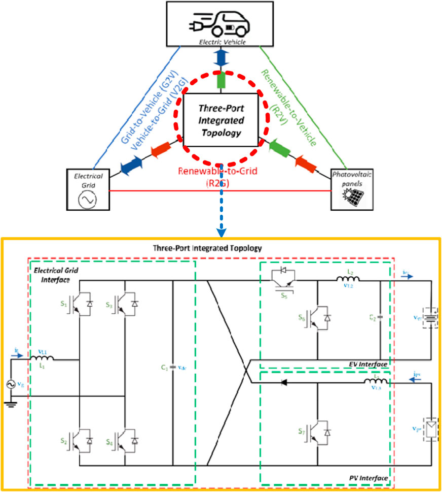
The solar photovoltaic system (SPS) is connected to a common DC link via a unidirectional DC-DC converter. Maximum power point (MPP) tracking requires this converter. Power can flow from the vehicle’s batteries in both directions because they are connected to a DC connection through a bidirectional DC-DC converter. Electricity can move from AC to DC and DC to AC thanks to a bidirectional AC-DC converter that connects the electric grid to the common DC connection. The future smart grid can take advantage of new opportunities provided by these modes of operation (R2G, R2V, G2V, and V2G), as shown in Figure 1. Complete elimination of conventional IC engine vehicles is still impossible because of some drawbacks EVs possess. These include energy storage systems, charging stations, and short driving mileage because of the charging capacity of batteries. Thus, automobile manufacturers are trying to improve EVs with better energy management and fuel efficiency. High-tech equipment like sensors, proper storage devices, and efficient power electronics devices are employed to improve the efficiency and reliability of the system. However, these technologies make electric vehicles more complicated and increase production costs. Therefore, there is a need for some economic technology in society.
As a result, the primary motivation and impetus of this proposed research are to maximize the energy generated by solar PV, optimize energy balance, maximize cost benefits, improve SOC, and regulate EV battery charging and discharging to improve battery life and system efficiency.
1.4 Layout of the work
The paper is organized in several sections. Here, a solar fed EV integrated with the grid is studied. A three-port integrated topology is analysed and controllers for three converters are designed in this study. Various MPPT algorithms are being investigated in order to harvest the most power from PV. The variation of solar power with changing air conditions is investigated. The extensive studies are performed with four modes of operation of the designed system, namely, R2G, R2V, V2G, and G2V at different conditions.
2 System descriptions and modelling
The integration of solar PV and electric vehicle with the electric grid is done by using power electronics converters (Chauhan et al., 2021). The TPIT algorithm uses three converters to interface three port with the common dc link.
• A unidirectional DC-DC converter to connect solar PV to the dc link. In this study, a boost converter is employed to implement the P&O algorithm.
• A bidirectional DC-DC converter connects the battery modelled as the EV’s storage element to the common dc link. When the battery sends power to the dc link, the converter operates as a boost converter; when power is stored in the battery, the converter acts as a buck converter. Power can flow in both directions with this converter.
• A bidirectional AC-DC converter is provided to linkage between electric grid with the common dc link. This converter allows the operation of V2G, G2V and R2G modes. Power can be taken or supplied to the grid according to the demand.
The TPIT algorithm with grid, renewables and electric vehicle is as shown in Figure 2. The four modes of operations are shown: R2G, R2V, V2G, and G2V (Ota et al., 2012; Tushar et al., 2018; Saber and Venayagamoorthy, 2011). The integration of grid with solar PV and EV is done by using the classical approach as shown in Figure 2A. This approach uses an AC-DC converter and then DC-DC converter for interfacing the grid with the vehicle or PV. The concept of common dc link is not implemented in that approach. This approach uses a greater number of converters which increases the system size, it’s cost and losses. The proposed approach as shown in Figure 2B, first converts AC to DC by using a converter and this dc forms a common dc link from which all other elements are connected. This approach ensures that lesser number of converters are used, and also the efficiency and reliability of the system is more over the classical approach. As the conversion takes place in lesser time, the harmonics injected to the grid current will be comparatively less and a common constant dc voltage can be obtained at the dc link where other dc loads can be connected directly without using another AC-DC converter (Sun et al., 2019).
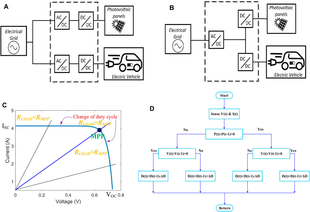
Figure 2. EV and solar interfaced with grid (A) Classical Topology (B) Proposed topology. (C) Graph depicting variation of maximum power point with duty cycle. (D) Flowchart of perturb and observe method.
The modelling of the solar PV is done here and MPPT algorithm is implemented by using a boost converter. All the three converters are designed along with the controllers such that the energy is balanced in the system.
2.1 Modelling of solar PV panel
Photoelectric processes are used in solar cells to transform the Sun’s light energy into electrical energy. These sun-facing PV cells are joined together to form a larger unit known as a PV module. PV clusters are formed by connecting these modules in series and parallel (Tiwari and Ghosh, 2020; Mazumdar et al., 2024a).
The output current mathematical equation of one PV equivalent model is represented by Chauhan et al. (2021) as in Equation 1:
where V is the output PV voltage, Ir is the saturation current, Iph is the photocurrent, q is the charge of an electron, k is the Boltzmann’s constant and T is the temperature. MPPT is the maximum dissipated power point on the current-voltage curve. The optimal efficiency is defined as the maximum power to incident light power ratio as shown in Equation 2.
where ƞmax is the efficiency,
2.2 Modelling of DC-DC power converter
Consider an ideal lossless DC-DC power converter. This converter is believed to be in continuous conduction mode (CCM) with a constant duty-cycle (D). The output and input voltage and current levels vary, but the total input power is always equal to the total output power. Pin = Pout, irrespective of the duty cycle (Khan et al., 2018).
Equations 3–5 show the relationship between the DC-DC power converter’s output voltage (Vo) and input voltage (Vin), as well as the relationship between the output current (Io) and input current (Iin) as a function of duty cycle D (Mahafzah et al., 2022).
The input impedance Zin depends on the duty cycle D and output impedance Zo. For different DC-DC converters, f(D) is different and hence the operating region is also different.
2.3 MPPT technique–perturb and observe technique
The maximum power point (MPP) of a PV module is tracked using MPPT algorithms (Mazumdar et al., 2024b; Mahafzah et al., 2022; Mazumdar et al., 2024c). This point is tracked using a variety of techniques and algorithms. The algorithm choice is dependent on its time complexity to track the MPP, implementation cost of algorithm and its ability to follow MPP when the atmospheric conditions such as irradiance and temperature fluctuations. Some MPPT techniques include fixed duty cycle technique, constant voltage (CV) method, incremental conductance method, and perturb and observe (P&O) method (Mazumdar et al., 2024b). Among these methods, P&O method is the most commonly used algorithm as discussed in this work.
The Perturb & Observe strategy is the most common and simplest way for MPPT. The PV panel voltage is sensed using a voltage sensor in this manner. As only one sensor is required, the implementation cost of this algorithm is less, and the complexity is also reduced. This algorithm takes less time to calculate the maximum power, but when it gets close to the MPP, it continues to perturb in both directions and does not stop at the MPP.
The weather influences the open circuit (OC) voltage and short circuit (SC) current, causing the maximum power to fluctuate. As the sun’s irradiation increases, so do the OC voltage and SC current. A voltage controller can be used to maintain a constant voltage at the output despite changes in irradiance and temperature.
The Perturb and Observe technique remains a fundamental method in MPPT, valued for its balance of simplicity, effectiveness, and cost-efficiency.
2.3.1 Overview
• The P&O technique is an iterative method used to maximize the power output of a PV system by continuously adjusting the operating voltage or current.
• It works by perturbing (i.e., slightly changing) the operating point of the PV system and observing the resulting change in power output.
• The main objective is to track the Maximum Power Point (MPP), where the PV system operates at maximum efficiency.
2.3.2 Working principle
1. Perturbation: The technique involves incrementing or decrementing the voltage or current of the PV module by a small amount.
2. Observation: After the perturbation, the power output of the PV system is observed.
o If the power increases, the perturbation moves in the same direction (e.g., if the voltage was increased, it continues to increase).
o If the power decreases, the direction of the perturbation is reversed.
3. Repeat: This process is repeated continuously to maintain operation at or near the MPP.
2.3.3 Advantages
• Simplicity: The P&O technique is relatively simple to implement and requires minimal computational resources.
• Low Cost: It is cost-effective, making it suitable for small-scale PV applications.
2.3.4 Disadvantages
• Oscillations around MPP: The method can cause the operating point to oscillate around the MPP, leading to minor power losses.
• Slow Response: In rapidly changing environmental conditions (e.g., fluctuations in sunlight), the P&O technique may respond slowly, causing temporary deviations from the MPP.
• Incorrect Tracking in Complex Conditions: Under certain conditions, such as partial shading, the P&O technique might track a local maximum instead of the global MPP.
2.3.5 Applications
• The P&O technique is widely used in small to medium-scale solar power systems, including standalone PV systems, hybrid systems, and grid-connected solar inverters.
2.4 Triple port integrated topology (TPIT)
Figure 3 displays the circuit diagram for the TPIT. The dc link is connected to the power grid via the bidirectional AC-DC converter. The bidirectional DC-DC converter connects the electric car batteries, whereas the unidirectional DC-DC converter connects the solar PV panel. TPIT unifies all of these converters into a single common dc link while preserving the features of each converter. The operating mode of the system determines the direction of power flow in each converter so that the voltage of the dc connection remains constant. This topology has four distinct types of operation.
I. R2G mode: The power generated by the solar PV is sent into the grid via a chopper and then to a DC-AC converter in this strategy.
II. R2V mode: In this mode, the battery of the electric vehicle is charged using the PV power that is generated. By permitting current to flow, the bidirectional converter raises the SOC and charges the battery.
III. V2G mode: In this mode of operation, the grid receives the necessary power from the electric vehicle. The system’s supply is guaranteed to remain constant in this mode.
IV. G2V mode: When the vehicle’s required power is not supplied by solar, the grid meets the surplus power requirement via this operating mode. The alternating current power from the grid is converted to direct current and used to charge the battery through an AC-DC converter. In this instance, the battery’s state of charge (SOC) rises.
3 Controller design
PI controllers are provided for controlling the voltage and current of the above-mentioned power electronics converters in this proposed work. The IGBT switches are controlled from the output of PI controllers such that the voltage and current error leads to zero, i.e., the voltage and current follows their respective reference value.
3.1 Bidirectional DC-DC converter
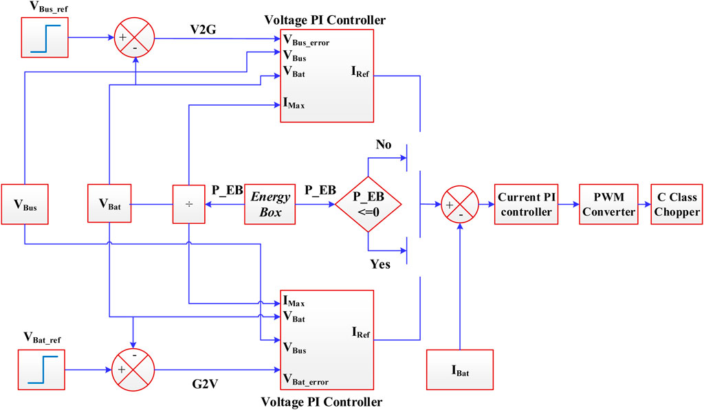
Two operating modes are provided for this proposed bidirectional half-bridge DC-DC converter controller system. These modes are known as G2V and V2G mode. In G2V mode, this chopper functions as a buck converter. The current is flowing in the direction of the battery. The converter functions as a boost converter in V2G mode.
The V2G and G2V chopper controllers are based on two PI daisy chain topologies, shown in Figure 4, which can provide effective power level control for each operation mode. First, the power level is controlled by stabilising the DC bus and the battery voltage for V2G and G2V, respectively. The voltage error is fed to the PI controller V2G or G2V through two differential comparators that compare the reference bus voltage (VBus_ref) and battery voltage (VBat). If VBus_ref is more than VBat (i.e., voltage error is +ve) the PI controller associated with G2V mode will operate otherwise PI controller associated with V2G mode will work for–ve voltage error (i.e., VBus_ref < VBat). The Energy Box (EB) is in charge of controlling G2V/V2G operation modes by sending instruction signals to the charger controllers. The EB takes advantage of consumers’ customary flexibility in load operation scheduling to achieve targeted demand response actions and optimal worldwide control of energy resources. The voltage controller’s current limit output response is determined by the ratio of the available power signal from the EB to the measured VBat. As a result, this controller dynamically limits the current reference (IRef) based on the available power signal. Following that, there is a differential comparator that compares Iref to battery current (IBat), and the produced signal is sent through the current controller. The current controller can control the inductor current of the chopper for maintain the regulation. The C class chopper is a DC-DC converter, which allows operating in the first two quadrants (i.e., positive voltage and positive & negative current). Handling the ratio relation between the chopper sides is possible through a pulse width modulation (PWM) signal, where the drive (Ton) and cut-off (Toff) times form one switching period (T) for each power switch. The voltage conversion ratio of this circuit is given by the duty-cycle of the converter.
⁃ For Buck mode of operation (S2 is OFF, D1 is OFF) VBat is expressed as in Equation 6:
Where, D is the duty cycle as in Equation 7, TON is the ON time, T is the switching period,
1. When S1 is ON and D2 is OFF. VBat is expressed as in Equation 8.
2. When S1 is OFF and D2 is ON. VBat is expressed as in Equation 9.
⁃ For Boost mode of operation (S1 is OFF, D2 is OFF). VBat is expressed as in Equation 10:
1. When S2 is ON and D1 is OFF. VBat is expressed as in Equation 11.
2. When S2 is OFF and D1 is ON. VBat is expressed as in Equation 12.
For the designing of the converter,
For the designing of voltage controller, transfer function can be derived in Equation 13:
For the designing of current controller, transfer function can be derived in Equation 14:
From Equation 15, it is understood that when inductor current
3.2 Bidirectional AC-DC converter controller
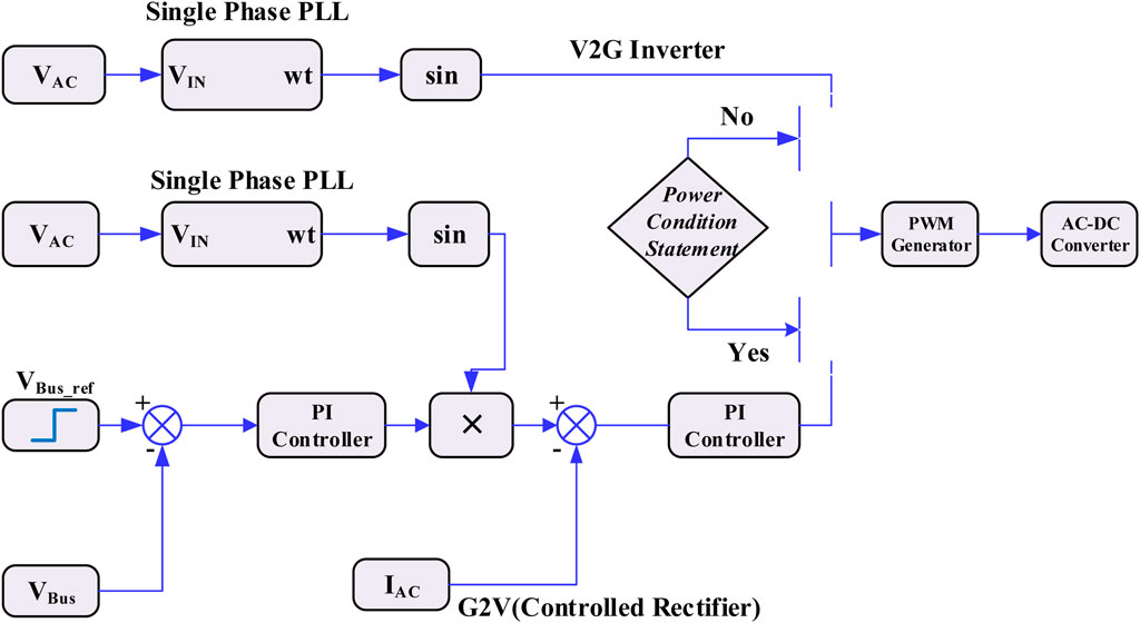
The AC-DC converter is also controlled by using PI controller. When the converter behaves as a controlled rectifier, a dual loop controller is designed such that the dc bus voltage and the ac current is regulated as shown in Figure 5. The dc bus voltage is controlled by the outer loop and gives the reference of ac grid current. For grid current regulation, a phase locked loop (PLL) is implemented which, along with voltage controller output gives the current reference.
4 Simulation results and discussions
4.1 Bidirectional DC-DC converter
Bidirectional converter operates in two modes.
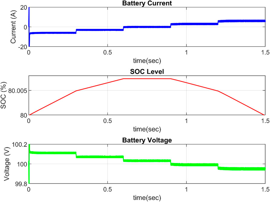
i) When the converter is used as a buck converter, power flows from the dc bus to the battery. As demonstrated in Figure 6, the battery charges and the SOC rises. In this mode, the current flow is interpreted as negative (sign convention). The battery is charged at various rates between t = 0 and t = 0.6 s.
ii) When the converter is used as a boost converter, power is given to the dc side and the battery is depleted, as shown in Figure 7 from t = 0.9 s to t = 1.5 s.
When the battery does neither store nor deliver energy between t = 0.6 and t = 0.9 s, the current is zero and the SOC is constant.
4.2 Battery charging from solar PV with varying load
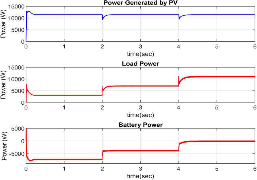
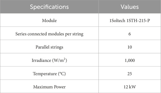
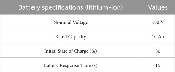
MATLAB/Simulink is used to model the three-port integrated design that links solar PV and electric vehicles to the grid. In order to evaluate the power flow in the proposed system, a variety of dc loads are applied across the dc connection in this section. The specifications of the PV panels and battery used in the system design are displayed in Tables 1, 2. This section looks into how battery power fluctuates under different loads.
Case I. When load is varying and PV generation is constant
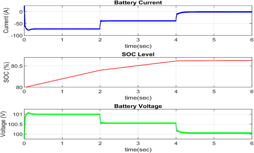
In this situation, the atmospheric conditions under which the power is created are kept constant. Figure 7 depicts the effect of changing the load power in three levels on the battery power. When the load power is less than the generated power, excess energy is stored in the battery. As seen in Figure 8, the battery characteristic fluctuates with the amount of energy stored or provided by the battery. As the battery charges, the SOC rises. In this mode, the current flow is initially negative and progressively increases to zero. The battery voltage gradually decreases from 101 V to 100.5 V until reaching 100 V.
Case II. When generated PV power is not constant and Load power is fluctuating
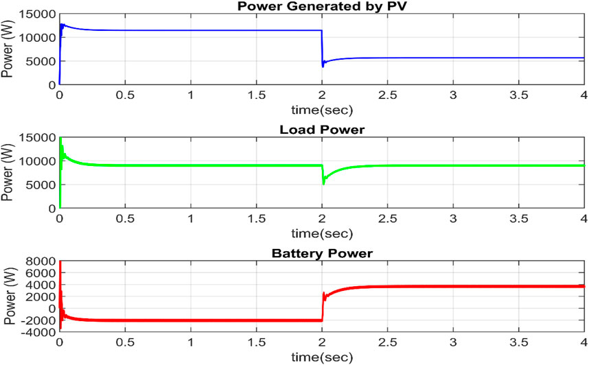
The load is not changed in this scenario, but the irradiance level is reduced from 1,000 W/m2 to 5,00 W/m2 at t = 2 s. When the irradiance is cut in half, the PV power is similarly cut in half, as illustrated in Figure 9. To supply the excess demand, the battery gets discharged and supplies its stored energy from t = 2 s. The load power demand is 10,000 W and tries to maintain constant. When the load power is greater than generated power, the excess energy is supplied from the battery and load power is maintained fixed.
4.3 Different operating modes of TPIT algorithm
The three power electronics converters which interface PV panel, EV modelled as Battery and Electric Grid are connected. This algorithm allows the system to operate in different modes. The basic four modes are R2V, R2G, G2V and V2G mode. The operating characteristics for all the modes are analysed in this section.
Mode I. R2V Operational mode
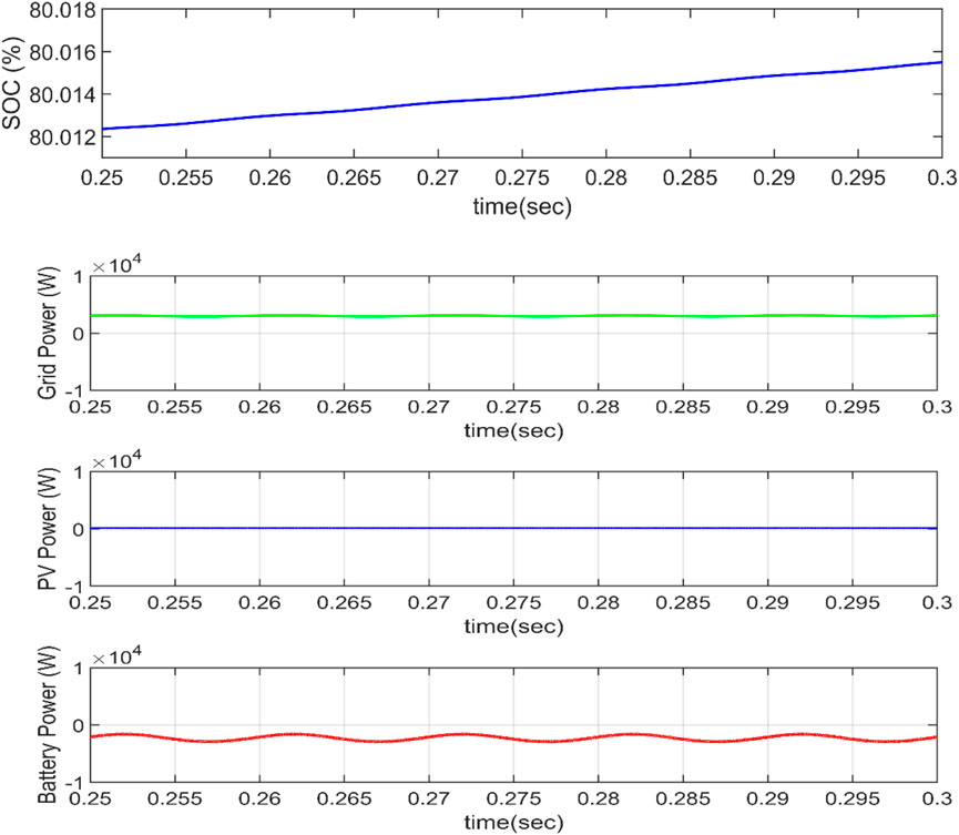
In R2V mode, the power generated by solar PV is stored by the vehicle’s battery and grid does not supply or take any power. As the grid does not play any role in this mode, the grid current is zero. The Battery stores the PV power and as a result its SOC increases. The energy is transferred from the solar PV to the EV battery directly. There is no power exchange, interaction or impact on the grid.
Mode II. G2V Operational mode
The car uses grid electricity when in G2V mode. The bidirectional AC-DC converter acts as a regulated rectifier, converting grid ac power to dc, which charges the battery via the DC-DC converter and steadily raises battery SOC. Figure 10 depicts the power flow balance for this mode. As the grid supplies power, the grid current and voltage are in phase.
Mode III. R2G Operational mode
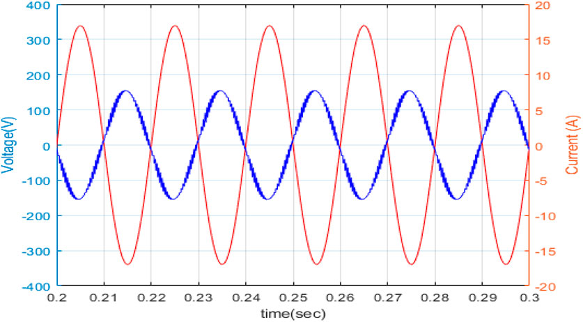
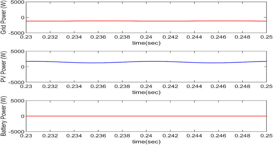
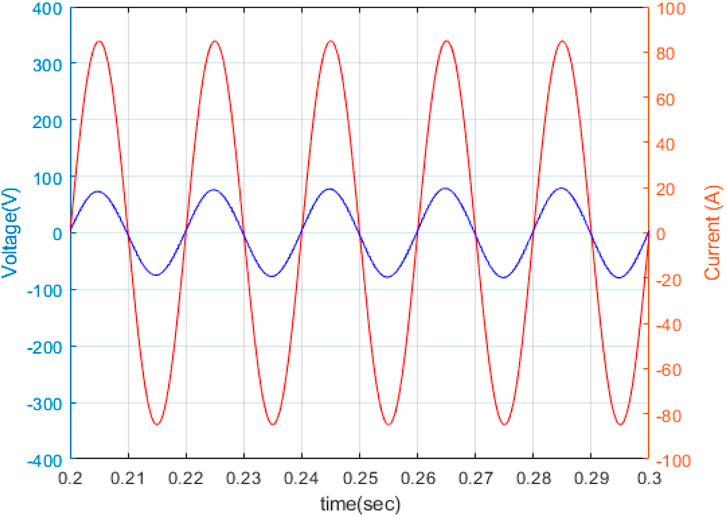
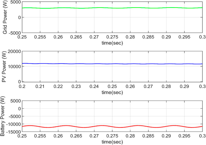
Solar PV power can be fed into the main power grid in this mode. The AC-DC converter functions as an inverter, converting direct current power from the PV to alternating current power. Because the power flow is in the direction of the grid, the grid current and voltage are out of phase, as illustrated in Figure 11. In Figure 12, the electricity supplied by the grid is considered positive, while the power taken or stored by the grid is considered negative. Because the complete PV electricity is delivered to the grid, battery storage consumes no power.
Mode IV. V2G Operational mode
When in V2G mode, the vehicle’s battery sends power to the grid. This kind of functioning might be used in future smart homes, with the car supplying electricity to the home in the event of a power outage. As power is supplied to the grid, the grid current and voltage will be out of phase, as seen in Figure 13.
Mode V. R2V + G2V Mode of Operation
Aside from the fundamental four modes of operation, these modes can be combined to generate other modes of operation such as R2V + G2V and R2G + V2G. The solar PV and grid both deliver power to the car in R2V + G2V mode of operation. As seen in Figure 14, the grid voltage and current are in the same phase, showing that the electricity is provided by the grid. Figure 15 displays the power balance of the system. Because the PV power exceeds the grid power, the excess power (after transferring to the grid) must be transferred to battery storage.
5 Conclusion
The novel triple-port DC-DC converter developed in this paper represents a significant advancement in DC microgrid technology. By facilitating efficient and flexible energy management among multiple sources and storage systems, this converter addresses the critical challenges of integrating renewable energy, enhancing system reliability, and improving overall efficiency. The proposed design and control strategies offer a promising solution for modern DC microgrids, paving the way for more sustainable and resilient energy infrastructures. Detailed simulations and experimental validations underscore the converter’s effectiveness, demonstrating its potential to transform DC microgrid applications. The system is designed, and the different modes of operation are analyzed for the system. A control algorithm is studied that interfaces renewables and EVs with the electric grid. The three power electronic converters are discussed, and their controllers are designed to maintain energy balance and stability in all cases. The battery characteristics indicate the operating mode. The phase between grid voltage and grid current indicates whether power is supplied by the grid or drawn from it. Integrating solar-fed EVs with the electric grid results in optimal system performance, contributing to a greener environment. The R2G and R2V modes of operation ensure the proper utilization of generated solar power. The G2V operating system makes the system more reliable and provides a continuous power supply that is ensured even during the night or cloudy days. V2G operating mode allows the vehicle to provide power to the grid when needed, which helps make the grid an intelligent grid. The control and power flow algorithms have been analyzed in this research. The triple port integrated topology ensures the proper power flow between the source and load during different conditions. A triple-port converter integrates three different ports (typically for renewable energy sources, energy storage, and loads), which requires complex control strategies to manage simultaneous power flow. Achieving seamless coordination between these power paths adds complexity to both hardware and software design. Control algorithms must dynamically balance power among the three ports while maintaining efficiency. This often requires more sophisticated methods such as Model Predictive Control (MPC) or fuzzy logic, which can be computationally intensive and difficult to implement in real-time applications. In the future, considering home loads and combining them with the intended system may lead to the smart grid concept. The future scope of this work could include a real-time implementation with experimental examination of the system and performance analysis.
Data availability statement
The original contributions presented in the study are included in the article/supplementary material, further inquiries can be directed to the corresponding authors.
Author contributions
HT: Writing–review and editing, Writing–original draft. AG: Writing–review and editing, Writing–original draft. SB: Writing–review and editing, Writing–original draft. DM: Writing–review and editing, Writing–original draft. CS: Writing–review and editing, Writing–original draft. FA: Writing–review and editing, Writing–original draft. TU: Writing–review and editing, Writing–original draft.
Funding
The author(s) declare that no financial support was received for the research, authorship, and/or publication of this article.
Conflict of interest
The authors declare that the research was conducted in the absence of any commercial or financial relationships that could be construed as a potential conflict of interest.
The author(s) declared that they were an editorial board member of Frontiers, at the time of submission. This had no impact on the peer review process and the final decision.
Publisher’s note
All claims expressed in this article are solely those of the authors and do not necessarily represent those of their affiliated organizations, or those of the publisher, the editors and the reviewers. Any product that may be evaluated in this article, or claim that may be made by its manufacturer, is not guaranteed or endorsed by the publisher.
Abbreviations
CCM, Continuous Conduction Mode; EV, Electric Vehicle; EMS, Energy Management System; G2V, Grid to Vehicle; ICE, Internal Combustion engine; MPPT, Maximum Power Point Tracking; PV, Photovoltaic; P&O, Perturb and Observe; R2G, Renewable to Grid; R2V, Renewable to Vehicle; SOC, State of Charge; TPIT, Triple Port Integrated Topology; V2G, Vehicle to Grid; VSI, Voltage Source Inverter.
References
Abdolrasol, M., G. M., Hannan, M. A., Hussain, S. M. S., Sarker, M. R., and Ker, P. J. (2021). Energy management scheduling for microgrids in the virtual power plant system using artificial neural networks. Energies 14, 6507. doi:10.3390/en14206507
Akar, F., Tavlasoglu, Y., Ugur, E., Vural, B., and Aksoy, I. (2016). A bidirectional non-isolated multi-input DC–DC converter for hybrid energy storage systems in electric vehicles. IEEE Trans. Veh. Technol. 65 (10), 7944–7955. doi:10.1109/TVT.2015.2500683
Barik, A. K., Das, D. C., Latif, A., Hussain, S. M. S., and Ustun, T. S. (2021). Optimal voltage–frequency regulation in distributed sustainable energy-based hybrid microgrids with integrated resource planning. Energies 14, 2735. doi:10.3390/en14102735
Basu, J. B., Dawn, S., Saha, P. K., Chakraborty, M. R., and Ustun, T. S. (2022). Economic enhancement of wind–thermal–hydro system considering imbalance cost in deregulated power market. Sustainability 14, 15604. doi:10.3390/su142315604
Chauhan, A., Upadhyay, S., Khan, M. T., Hussain, S. M. S., and Ustun, T. S. (2021). Performance investigation of a solar photovoltaic/diesel generator based hybrid system with cycle charging strategy using BBO algorithm. Sustainability 13, 8048. doi:10.3390/su13148048
Chen, X., Xu, G., Xie, S., Han, H., Su, M., Sun, Y., et al. (2020). A natural bidirectional input-series–output-parallel LLC-DCX converter with automatic power sharing and power limitation capability for Li-ion battery formation and grading system. IEEE J. Emerg. Sel. Top. Power Electron. 8 (4), 3618–3632. doi:10.1109/JESTPE.2019.2941583
de Melo, R. R., Tofoli, F. L., Daher, S., and Antunes, F. L. M. (2020). Interleaved bidirectional DC–DC converter for electric vehicle applications based on multiple energy storage devices. Electr. Eng. 102, 2011–2023. doi:10.1007/s00202-020-01009-3
de Quevedo, P. M., Muñoz-Delgado, G., and Contreras, J. (2018). Impact of electric vehicles on the expansion planning of distribution systems considering renewable energy, storage and charging stations. 2018 IEEE Power and Energy Soc. General Meet. (PESGM), 1. doi:10.1109/PESGM.2018.8586628
Dey, B., Roy, B., Datta, S., and Ustun, T. S. (2023). Forecasting ethanol demand in India to meet future blending targets: a comparison of ARIMA and various regression models. Energy Rep. 9, 411–418. doi:10.1016/j.egyr.2022.11.038
Dey, P. P., Das, D. C., Latif, A., Hussain, S. M. S., and Ustun, T. S. (2020). Active power management of virtual power plant under penetration of central receiver solar thermal-wind using butterfly optimization technique. Sustainability 12, 6979. doi:10.3390/su12176979
Guo, Y., Xiong, J., Xu, S., and Su, W. (2016). Two-stage economic operation of microgrid-like electric vehicle parking deck. IEEE Trans. Smart Grid 7 (3), 1703–1712. doi:10.1109/TSG.2015.2424912
Gurugubelli, V., Ghosh, A., and Panda, A. K. (2023a). Design and implementation of optimized virtual oscillatory controllers for grid-forming inverters. ISA Trans. 139, 685–712. doi:10.1016/j.isatra.2023.04.015
Gurugubelli, V., Ghosh, A., Panda, A. K., and Behera, B. P. (2023b). Fuzzy-based adaptive VOC methods for parallel inverters. IEEE Trans. Power Electron. 39, 3956–3961. doi:10.1109/tpel.2023.3340883
Humfrey, H., Sun, H., and Jiang, J. (2019). Dynamic charging of electric vehicles integrating renewable energy: a multi-objective optimisation problem. IET Smart Grid 2 (2), 250–259. doi:10.1049/iet-stg.2018.0066
Hussain, I., Das, D. C., Sinha, N., Latif, A., Hussain, S. M. S., and Ustun, T. S. (2020a). Performance assessment of an islanded hybrid power system with different storage combinations using an FPA-tuned two-degree-of-freedom (2DOF) controller. Energies 13, 5610. doi:10.3390/en13215610
Hussain, S. M. S., Aftab, M. A., Ali, I., and Ustun, T. S. (2020b). IEC 61850 based energy management system using plug-in electric vehicles and distributed generators during emergencies. Int. J. Electr. Power and Energy Syst. 119, 105873. doi:10.1016/j.ijepes.2020.105873
Huynh, D. C., and Dunnigan, M. W. (2016). Development and comparison of an improved incremental conductance algorithm for tracking the MPP of a solar PV panel. IEEE Trans. Sustain. Energy 7 (4), 1421–1429. doi:10.1109/TSTE.2016.2556678
IEA (2024). Global EV outlook 2024. Paris: IEA. Available at: https://www.iea.org/reports/global-ev-outlook-2024.
Joarder, S., Ghosh, A., Banerjee, S., Sain, C., and Ahmad, F. (2024). Harmonic modelling and control of dual active bridge converter for DC microgrid applications. Energy Rep. 12, 52–74. doi:10.1016/j.egyr.2024.05.015
Joarder, S., and Ghosh, A. (2022). “Design and implementation of dual active bridge converter for DC microgrid application,” in 2022 IEEE Delhi Section Conference (DELCON), China, 11-13 Feb. 2022, 1–6. doi:10.1109/delcon54057.2022.9753372
Khan, A., Memon, S., and Sattar, T. P. (2018). Analyzing integrated renewable energy and smart-grid systems to improve voltage quality and harmonic distortion losses at electric-vehicle charging stations. IEEE Access 6, 26404–26415. doi:10.1109/ACCESS.2018.2830187
Lee, W., Xiang, L., Schober, R., and Wong, V. W. S. (2015). Electric vehicle charging stations with renewable power generators: a game theoretical analysis. Denver, CO, USA: IEEE Power and Energy Society General Meeting, 1. doi:10.1109/PESGM.2015.7286014
Liu, C., Chau, K. T., Wu, D., and Gao, S. (2013). Opportunities and challenges of vehicle-to-home, vehicle-to-vehicle, and vehicle-to-grid technologies. Proc. IEEE 101 (11), 2409–2427. doi:10.1109/JPROC.2013.2271951
liu, Z., Wu, Q., Shahidehpour, M., Li, C., Huang, S., and Wei, W. (2019). Transactive real-time electric vehicle charging management for commercial buildings with PV on-site generation. IEEE Trans. Smart Grid 10 (5), 4939–4950. doi:10.1109/TSG.2018.2871171
Mahafzah, K. A., Obeidat, M. A., Al-Shetwi, A. Q., and Ustun, T. S. (2022). A novel synchronized multiple output DC-DC converter based on hybrid flyback-cuk topologies. Batteries 8, 93. doi:10.3390/batteries8080093
Mazumdar, D., Biswas., P. K., Sain, C., Ahmad, F., Sarker, R., and Ustun, T. S. (2024c). Optimising MPPT control for enhanced efficiency in sustainable photovoltaic microgrids: a DSO-based approach. Int. Trans. Electr. Energy Syst. Article ID 5525066. doi:10.1155/2024/5525066
Mazumdar, D., Biswas., P. K., Sain, C., Ahmad, F., Ustun, T. S., and Kalam, A. (2024a). Performance analysis of drone sqadron optimisation based MPPT controller for grid implemented PV battery system under partially shaded conditions. Renew. Energy Focus 49, 100577. doi:10.1016/j.ref.2024.100577
Mazumdar, D., Biswas, P. K., Sain, C., and Ustun, T. S. (2024b). GAO optimized sliding mode based reconfigurable step size Pb&O MPPT controller with grid integrated EV charging station. IEEE Access 12, 10608–10620. doi:10.1109/ACCESS.2023.3344275
Mohsenian-Rad, A. H., Wong, V. W. S., Jatskevich, J., Schober, R., and Leon-Garcia, A. (2010). Autonomous demand-side management based on game-theoretic energy consumption scheduling for the future smart grid. IEEE Trans. Smart Grid 1 (3), 320–331. doi:10.1109/TSG.2010.2089069
Monteiro, V., Pinto, J. G., and Afonso, J. L. (2018). Experimental validation of a three-port integrated topology to interface electric vehicles and renewables with the electrical grid. IEEE Trans. Industrial Inf. 14 (6), 2364–2374. doi:10.1109/TII.2018.2818174
Mutoh, N., Ohno, M., and Inoue, T. (2006). A method for MPPT control while searching for parameters corresponding to weather conditions for PV generation systems. IEEE Trans. Industrial Electron. 53 (4), 1055–1065. doi:10.1109/TIE.2006.878328
Ota, Y., Taniguchi, H., Nakajima, T., Liyanage, K. M., Baba, J., and Yokoyama, A. (2012). Autonomous distributed V2G (Vehicle-to-Grid) satisfying scheduled charging. IEEE Trans. Smart Grid 3 (1), 559–564. doi:10.1109/TSG.2011.2167993
Panda, S. K., and Ghosh, A. (2018). “A low ripple load regulation scheme for grid connected microgrid systems,” in 2018 IEEE 8th Power India International Conference (PIICON), Kurukshetra, India, 10-12 Dec. 2018, 1–6. doi:10.1109/POWERI.2018.8704358
Reddi, C., and Ghosh, A. (2024). “Bidirectional DC converter using Li-Ion battery for EV Applications,” in 2024 IEEE 13th International Conference on Communication Systems and Network Technologies (CSNT), USA, 6 April 2024, 1270–1275. doi:10.1109/csnt60213.2024.10546150
Rigas, E. S., Ramchurn, S. D., and Bassiliades, N. (2015). Managing electric vehicles in the smart grid using artificial intelligence: a survey. IEEE Trans. Intelligent Transp. Syst. 16 (4), 1619–1635. doi:10.1109/TITS.2014.2376873
Saber, A. Y., and Venayagamoorthy, G. K. (2011). Plug-in vehicles and renewable energy sources for cost and emission reductions. IEEE Trans. Industrial Electron. 58 (4), 1229–1238. doi:10.1109/TIE.2010.2047828
Sam, C. A., and Jegathesan, V. (2021). Bidirectional integrated on-board chargers for electric vehicles—a review. Sādhanā 46 (1), 26–14. doi:10.1007/s12046-020-01556-2
Sinha, S., and Ghosh, A. (2024). “Switching transients reduction for battery charging controller during mode selection,” in 2024 IEEE International Students' Conference on Electrical, Electronics and Computer Science (SCEECS), China, February 2024, 1–6. doi:10.1109/sceecs61402.2024.10481977
Sun, Y., Yue, H., Zhang, J., and Booth, C. (2019). Minimization of residential energy cost considering energy storage system and EV with driving usage probabilities. IEEE Trans. Sustain. Energy 10 (4), 1752–1763. doi:10.1109/TSTE.2018.2870561
Tiwari, H., and Ghosh, A. (2020). “Power flow control in solar PV fed DC Microgrid with storage,” in 2020 IEEE 9th Power India International Conference (PIICON), Sonepat, India, Dec 2020, 1–6. doi:10.1109/PIICON49524.2020.9112962
Tushar, M. H. K., Zeineddine, A. W., and Assi, C. (2018). Demand-side management by regulating charging and discharging of the EV, ESS, and utilizing renewable energy. IEEE Trans. Industrial Inf. 14 (1), 117–126. doi:10.1109/TII.2017.2755465
Ustun, T. S., and Hussain, S. M. S. (2019). “Implementation and performance evaluation of IEC 61850 based home energy management system,” in 2019 IEEE 8th Global Conference on Consumer Electronics (GCCE), Osaka, Japan, 15-18 Oct. 2019, 24–25.
Yarar, N., Yagci, M., Bahceci, S., Onen, A., and Ustun, T. S. (2023). Artificial neural networks based harmonics estimation for real university microgrids using hourly solar irradiation and temperature data. Energy Nexus 9, 100172. doi:10.1016/j.nexus.2023.100172
Yuan, J., Dorn-Gomba, L., Callegaro, A. D., Reimers, J., and Emadi, A. (2021). A review of bidirectional on-board chargers for electric vehicles. IEEE Access 9, 51501–51518. doi:10.1109/ACCESS.2021.3069448
Keywords: DC-DC converters, electric vehicles, PV system, three port integrated topology, voltage source inverter
Citation: Tiwari H, Ghosh A, Banerjee S, Mazumdar D, Sain C, Ahmad F and Ustun TS (2024) Design of a triple port integrated topology for grid-integrated EV charging stations for three-way power flow. Front. Energy Res. 12:1440258. doi: 10.3389/fenrg.2024.1440258
Received: 29 May 2024; Accepted: 25 October 2024;
Published: 08 November 2024.
Edited by:
Michael Carbajales-Dale, Clemson University, United StatesReviewed by:
Koorosh Gharehbaghi, RMIT University, AustraliaYingqi Liang, National University of Singapore, Singapore
Copyright © 2024 Tiwari, Ghosh, Banerjee, Mazumdar, Sain, Ahmad and Ustun. This is an open-access article distributed under the terms of the Creative Commons Attribution License (CC BY). The use, distribution or reproduction in other forums is permitted, provided the original author(s) and the copyright owner(s) are credited and that the original publication in this journal is cited, in accordance with accepted academic practice. No use, distribution or reproduction is permitted which does not comply with these terms.
*Correspondence: Furkan Ahmad, ZnVhaG1hZEBoYmt1LmVkdS5xYSYjeDAyMDBhOw==; Taha Selim Ustun, c2VsaW0udXN0dW5AYWlzdC5nby5qcA==
 Harshita Tiwari1
 Arnab Ghosh
 Furkan Ahmad
 Taha Selim Ustun
