- 1Department of Electrical and Information Engineering, Tianjin University, Tianjin, China
- 2Research Center, Ginlong Technologies Co., Ltd., Ningbo, China
Depending on the PV power, load power, and battery status, the system may operate in different modes. The control loop may have to switch between operating modes. In practice, it is difficult to implement control loop switching because the transition and dynamic process are difficult to control. As a result, this paper presents a generalized mode control method that avoids loop switching across modes. First, system structure and topology are introduced. The operating conditions for both grid-connected and off-grid modes are then divided into six sub-cases. Furthermore, the control architecture, control loop, and reference transition for various scenarios are described. Finally, an experimental platform is built, and the results are presented to verify the proposed method.
1 Introduction
As part of the global green mission, an increasing number of renewable energy sources are being installed. As renewable energy sources gain traction, power electronic converters become increasingly popular (Zhang et al., 2023a). The combination of solar panels and energy storage will be a trend in future energy development, and many experts have conducted extensive research on photovoltaic and energy storage hybrid systems (Zhang et al., 2023b). The system operates in a variety of modes depending on the operational conditions of photovoltaic, energy storage, and the power grid. The seamless transition between modes has also become a research topic (Hmad et al., 2023).
Several papers investigate the transition between grid-connected and offline modes; one of the mode transition control strategies relies on a virtual switch located between two functional modes (Balaguer-Alvarez et al., 2014). During grid-connected mode, the inverter functions solely as a current source, utilizing the current controller loop. When an islanding condition is detected, the virtual switch is assigned to the voltage loop. As a result, the inverter operates as a voltage source (Qinfei et al., 2017). The anti-islanding method has a strong influence on the transition performance. The majority of islanding detection methods rely on continuous monitoring of system characteristics at the point of common coupling (PCC), including current, voltage, frequency, and harmonics (Ahmad et al., 2013). These transition approaches can be classified into three categories: passive, active, and hybrid (Koohi-Kamali and Rahim, 2016; Aillane et al., 2023) presents an improved mode transition approach. During the transition, a super-twisting algorithm approach was used to ensure load voltage and manage the inverter’s nonlinear properties, resulting in a smooth transition with minimal disruption impacts. Ashabani and Mohamed (2014) investigates another switching-based method. Three different approaches are considered: power drooping current controlled, power drooping voltage controlled, and current drooping voltage controlled. Furthermore, to aid smooth mode transitions by dampening power, frequency, voltage, and current signals, an approach based on a supplement controller employing port-controlled hamiltonian (PCH) modeling and control was developed in (Azimi and Lotfifard, 2021). Another approach to achieving a seamless transition is to employ an extra distributed generation (DG) system, which is often a specialized storage unit (Jihed et al., 2019). The premise behind this technique entailed deploying a supplemental energy unit to relieve the transient, which, however, incurs additional expenditures.
The second set of solutions for dealing with the transition problem includes the use of an extra feedforward compensator (Tran et al., 2013). The basic idea behind this control structure group is to include a voltage loop in addition to the current loop when a grid fault occurs. In Hwang and Park (2013), an improved seamless transition based on a phase-locked loop (PLL) mechanism was developed for a three-phase grid-connected inverter. The control strategy entails modifying the PLL depending on the operating mode, synchronizing the output inverter voltage to the grid voltage in grid-connected mode, and generating an angle at the required frequency in off-grid mode. In Harirchi et al. (2015), a similar PLL-based transfer was performed, with feedforward voltage used to mitigate the transition’s negative effects on a three-phase grid-connected PV inverter.
Various research studies have developed transition control without reconfiguring the control structure, also known as unified control (Yi et al., 2018). The overall goal of this technique was to use the voltage control loop as a reference current generator when connected to the grid and as a voltage regulator when off-grid. Unlike previous transition structures, this technique does not necessitate any changes at the control level. Variants of the universal control system have been proposed as a solution to transition issues. In Liu and Liu (2014), the authors developed an indirect current control loop with an applied voltage loop for a three-phase inverter to ensure smooth transfer. In Sowa et al. (2021), a three-phase universal controller for flexible microgrids was presented, ensuring operation in all operating modes without the need for control structure reconfiguration. In Yi et al. (2018), the authors described a unified control and power management system for a hybrid PV-battery application that included both DC and AC charging buses. In Li et al. (2020), a non-linear-simplex method was proposed for determining the optimal controller settings with the goal of reducing voltage variation and achieving a seamless state transition. In the literature (Singh et al., 2017; Jihed et al., 2019), a unified system with droop control approach is investigated. The concept of droop methods has been widely applied to the parallel operation of DG inverters with voltage and/or current control loops. However, one major disadvantage of this method is its poor dynamic performance.
PV-battery hybrid systems operate in a variety of scenarios based on PV power, load power, and battery status, and the control loop may need to switch. Because transition and dynamic processes are difficult to control, it is difficult to implement control loop switching in practice. As a result, this paper proposes a generalized mode control method that avoids loop switching in a variety of scenarios. The main contributions are as follows.
1) This paper describes a generalized operating mode control method. The conditions in grid-connected and off-grid modes are classified into six scenarios based on the values of PV power PPV, load power Pload, battery state of charge (SOC), and so on. Furthermore, the control architecture, control loop, and reference transition for various scenarios are discussed.
2) In grid-connected mode, the battery-side DC/DC controls the DC-bus voltage, the PV-side DC/DC applies Maximum Power Point Tracking (MPPT) mode to maximize PV output power, and the grid-side DC/AC controls the output power. The control loops for DC/DC and Bi-DC/DC do not need to change in different operating scenarios; only the DC/AC output power reference does.
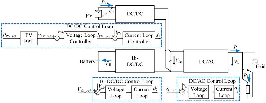
3) In off-grid mode, the battery-side DC/DC regulates the DC-bus voltage, the PV-side DC/DC uses power point tracking (PPT) mode to track the PV output power reference, and the grid-side DC/AC regulates the output voltage. The DC/AC and Bi-DC/DC control loops do not need to change in different operating scenarios, while only the PV-side DC/DC power reference does.
4) An experimental platform is built, and the results are presented to support the proposed method.
2 System structure and topology
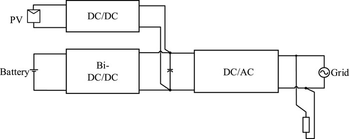
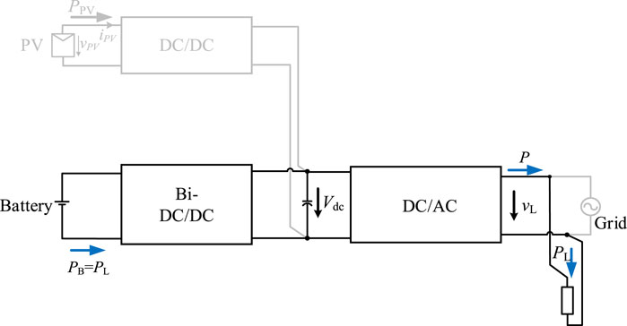
Figure 1 depicts the architecture of a typical PV-battery hybrid system, which is a common DC-bus structure. PVs, batteries, and the grid and load are connected to the DC-bus through DC/DC, bidirectional DC/DC, and DC/AC, respectively.
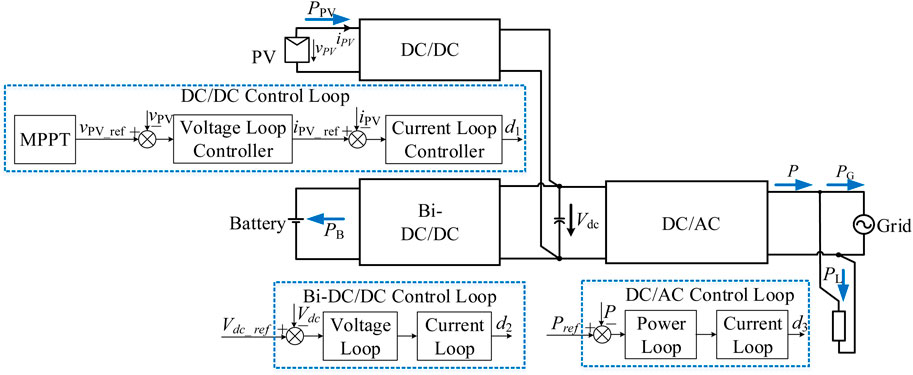
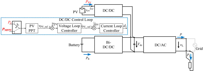
Figure 2 presents the system topology. The Boost topology is used for the PV-side DC/DC. A two-stage structure with LLC plus Buck/Boost is used for the battery-side Bi-DC/DC. The Highly Efficient Reliable Inverter Concept (HERIC) topology is chosen for the DC/AC side.
There are two operating modes for the system, which are grid-connected mode and off-grid mode. In the grid-connected mode, the grid is normal, and the system operates in current source mode, feeding power to the grid. In off-grid mode, the grid is not present, and the system operates in voltage source mode to ensure load voltage. Furthermore, depending on PV power, load power, and battery status, the system operates in different scenarios. Furthermore, the control loop may have to switch for different scenarios. Since the transition and dynamic process is difficult to control, it is relatively challenging to implement the control loop switching. Therefore, the following presents a generalized mode control method for avoiding loop switching for different scenarios.
3 System control
Before introducing specific methods, we set basic control prerequisites first. One of them is the priorities of power sources, including three points.
1) PVs are set as the first priority power source. The output power of PV modules should be prioritized to feed the load.
2) Batteries are set as the second priority power source. When there is a surplus or shortage of PV power to the load, the battery is then used to achieve power balance.
3) The grid is set as the third priority power source. When both the PV modules and the batteries reach their limits, the grid is then employed to power the load.
Furthermore, the output power of PV modules, the SOC of batteries, and the charging and discharging power of batteries are restricted as follows.
1) When the PV output power PPV is less than the set minimum threshold PPV_min, the PV is considered to have no power and the PV side is shut off; otherwise, the PV side should be used to generate power.
2) If the battery SOC is greater than 90%, the battery should not be charged further; if the battery SOC is less than 10%, the battery should not be drained further.
The following will analyze the grid-connected mode and off-grid mode, respectively.
3.1 Grid-connected mode
Based on the values of PV power PPV, load power Pload, battery SOC, etc., the operating conditions under the grid-connected mode are divided into six scenarios, as shown in Figure 3.
Figure 4 depicts the control architecture in grid-connected mode, where the battery-side DC/DC controls the DC-bus voltage Vdc, the PV-side DC/DC operates in MPPT mode to maximize the PV output power PPV, and the grid side DC/AC controls the output power P. The advantage of the control architecture shown in Figure 4 is that the control loops for DC/DC and Bi-DC/DC do not need to change in different operating scenarios, with only the DC/AC output power reference Pref needed to change. This reduces the control loops switching during different scenarios, making it simple to implement.
It is worth mentioning that, in this paper, vpv is PV voltage, vpv_ref is PV voltage reference, ipv is PV current, ipv_ref is PV current reference, Vdc_ref is DC-bus voltage reference, d1 is output duty cycle of the DC/DC control loop, d2 is output duty cycle of the Bi-DC/DC control loop, and d3 is output duty cycle of the DC/AC control loop.
3.1.1 Scenario A1
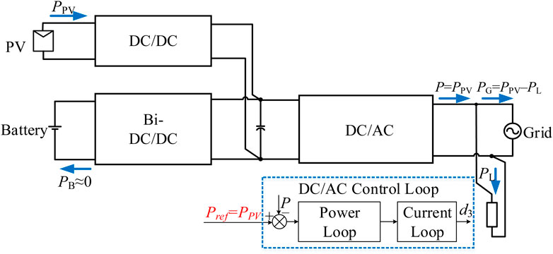
In this scenario, PPV > PLoad and SOC > 90%, where the PV power is larger than the load power and the battery cannot be charged. In the control loop, as shown in Figure 5, the DC/AC power reference Pref is set to PPV. This can result in that the DC/AC outputs the PV-side power PPV and the battery power PB is zero. Furthermore, the PV powers the load PL, and the extra power (PPV–PL) is fed to the grid, and the grid power is PG.
3.1.2 Scenario A2
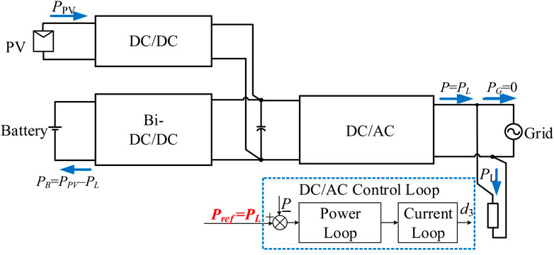
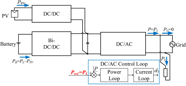
In this scenario, PPV > PLoad and SOC ≤ 90%, where the PV power is higher than the load power and the battery can be charged. In the control loop, as shown in Figure 6, the DC/AC power reference Pref is set to PL. This can result in that the DC/AC outputs the load power PL and the power fed into the grid is 0. Furthermore, the battery automatically absorbs the remaining power generated by PV, which is PPV–PL.
3.1.3 Scenario A3
In this scenario, PPV ≤ PLoad and SOC > 10%, where the PV power is less than the load power and the battery can be discharged. In the control loop, as shown in Figure 7, the DC/AC power reference Pref is set to PL. This can result in that the DC/AC outputs the load power PL and the power fed into the grid is 0. Furthermore, the battery automatically provides the remaining power PL–PPV.
3.1.4 Scenario A4
In this scenario, PPV ≤ PLoad and SOC ≤ 10%, where the PV power is less than the load power and the battery cannot be discharged. In the control loop, as shown in Figure 8, the DC/AC power reference Pref is set to PPV. This can result in that the DC/AC outputs the PV power PPV and the power that the battery provides is 0. Furthermore, the grid provides the remaining load power PL–PPV.
3.1.5 Scenario A5
In this scenario, PPV ≤ PPV_min and SOC > 10%, where the PV cannot generate power and the battery can be discharged to feed the load. In the control loop, as shown in Figure 9, the DC/AC power reference Pref is set to PL. This can result in that the DC/AC outputs the load power PL and the power from the grid is 0. Furthermore, the battery automatically provides the load power PL.
3.1.6 Scenario A6
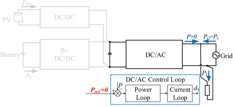
In this scenario, PPV ≤ PPV_min and SOC ≤ 10%, where the PV cannot generate power and the battery cannot be discharged to feed the load. Thus, the load power can only be provided by the grid. In the control loop, as shown in Figure 10, the DC/AC power reference Pref is set to 0. This can result in that the DC/AC outputs no power and the load power is from the grid.
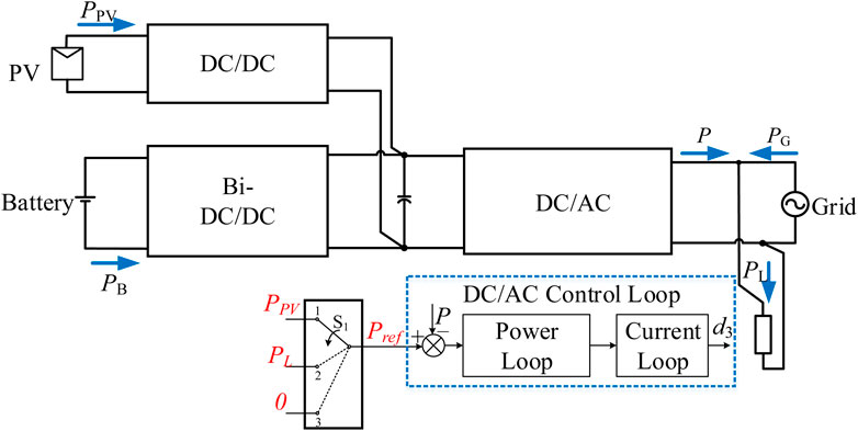
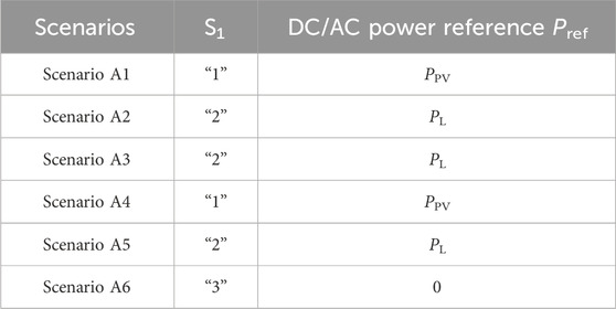
The summary of six scenarios for the grid-connected mode is shown in Figure 11. From it, a switch S1 is introduced to assign different DC/AC power references. In scenarios A1 and A4, the switch S1 is placed to “1”. In scenarios A2, A3, and A5, the switch S1 is placed to “2”. In scenario A6, the switch S1 is placed to “3”. The details are presented in Table 1.
3.2 Off-grid mode
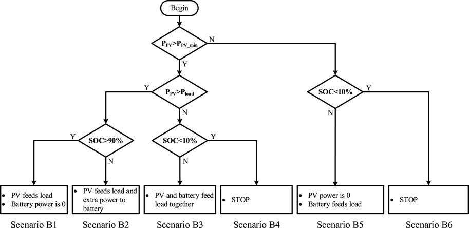
Based on the values of PV power PPV, load power Pload, battery SOC, etc., the operating conditions under the off-grid mode are divided into six different scenarios, as shown in Figure 12.
Figure 13 depicts the control mode in off-grid mode, where the battery-side Bi-DC/DC controls the DC-bus voltage Vdc, the PV-side DC/DC operates in power point tracking (PPT) mode to follow the PV output power PPV, and the grid-side DC/AC controls the output voltage vL. The advantage of the control architecture shown in Figure 13 is that the DC/AC and Bi-DC/DC control loops do not need to change in different operating scenarios, with only the PV-side DC/DC power reference PPV_ref needed to change. This reduces the control switching during different scenarios, making it simple to implement.
3.2.1 Scenario B1
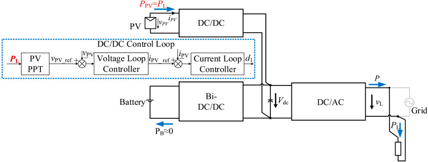
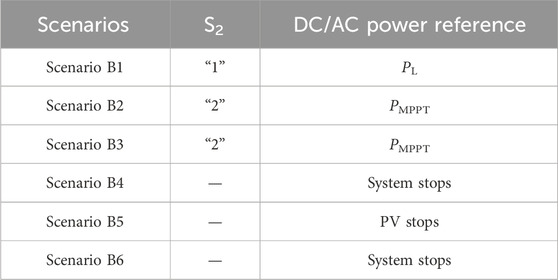
In this scenario, PPV > PLoad and SOC > 90%, where the PV power is larger than the load power and the battery cannot be charged. In the control loop, as shown in Figure 14, the PV-side DC/DC power reference PPV_ref is set to the load power PL. This can result in that the PV side cannot implement MPPT function, and the PV-side power PPV is limited to PL. Therefore, the PV provides the load power PL, and the power from the battery PB is zero.
3.2.2 Scenario B2
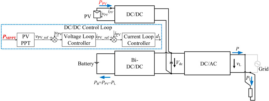
In this scenario, PPV > PLoad and SOC ≤ 90%, where the PV power is higher than the load power and the battery can be charged. In the control loop, as shown in Figure 15, the PV-side DC/DC performs MPPT function. This can result in that the PV-side DC/DC outputs the maximum power PMPPT. Furthermore, the battery automatically absorbs the extra power generated by PV, which is PPV–PL.
3.2.3 Scenario B3
In this scenario, PPV ≤ PLoad and SOC > 10%, where the PV power is less than the load power and the battery can be discharged to the load. In the control loop, as shown in Figure 16, the PV-side DC/DC performs MPPT. This can result in that the PV-side DC/DC outputs the maximum power PMPPT. Furthermore, the battery automatically provides the remaining power, which is PL–PPV.
3.2.4 Scenario B4
In this scenario, PPV ≤ PLoad, and SOC ≤ 10%, where the PV power is less than the load power and the battery cannot be discharged. Therefore, as shown in Figure 17, the system cannot operate.
3.2.5 Scenario B5
In this scenario, PPV ≤ PPV_min and SOC > 10%, where the PV cannot generate power and the battery can be discharged to feed the load. The PV-side DC/DC stops. Furthermore, the battery automatically provides the load power PL as shown in Figure 18.
3.2.6 Scenario B6
In this scenario, PPV ≤ PPV_min and SOC ≤ 10%, where the PV cannot generate power and the battery cannot be discharged to feed the load. Thus, as shown in Figure 19, the system cannot operate.
The summary of six scenarios for the off-grid mode is shown in Figure 20. From it, a switch S2 is introduced to set different DC/DC power references. In scenarios B1, the switch S2 is placed to “1”. In scenarios B2 and B3, the switch S2 is placed to “2”. In other scenarios, PV-side DC/DC stops. The details are presented in Table 2.
4 Experimental verifications
A platform is built and Figures 21–23 are the experimental results. Figure 21 depicts the experimental results for the grid-connected mode with no PV and the battery switched between charging and discharging. From Figure 21A, the system operates smoothly when the battery is switched from charging to discharging and the current is adjusted from −120 to +120 A. From Figure 21B, the battery is transitioning from charging to discharging, and the entire process is seamless. The battery current is changed from +120 to −120 A, and the grid current is adjusted correspondingly. The proposed mode transition method ensures a smooth transition between these two operational modes.
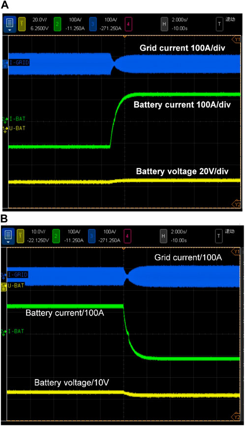
Figure 21. Experimental results for the grid-connected mode when there is no PV (A) battery charging to discharging; (B) battery discharging to charging.
Figure 22 depicts the experimental results of the transition between grid-connected mode and off-grid mode. From Figure 22A, the system operates smoothly and the load voltage remains stable when the system switched from grid-connected to off-grid mode. In grid-connected mode, the inverter functions as a current source. In the off-grid mode, however, the inverter functions as a voltage source. In addition, when the grid is normal, the battery is charging. When the grid is offline, the battery is switched to discharging mode to maintain the load voltage.
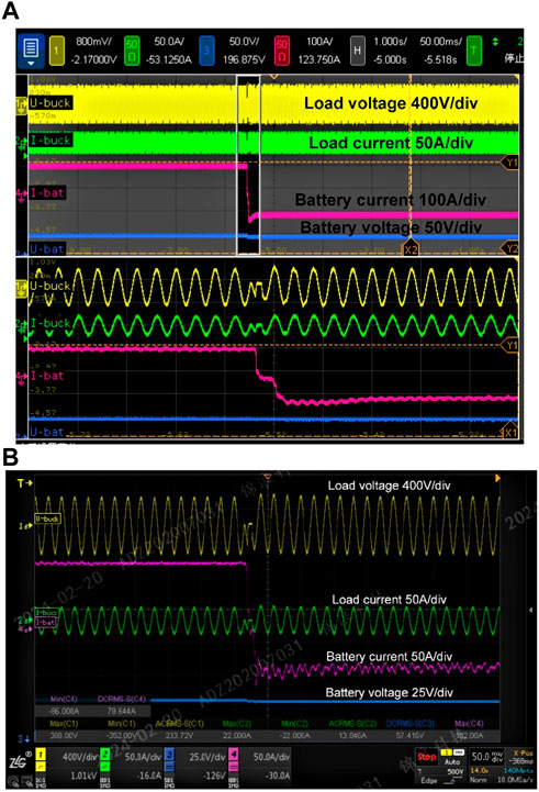
Figure 22. Experimental results between grid-connected mode and off-grid mode (A) grid-connected mode to off-grid mode; (B) off-grid mode to grid-connected mode.
From Figure 22B, the system operates smoothly and the load voltage remains stable when the system is switched from off-grid to grid-connected mode. The inverter switches from a voltage source in off-grid mode to a current source in grid-connected mode. In addition, the battery is in discharging mode to maintain the load voltage when the grid is offline. When the grid resumes to normal operation, the battery is switched to charging mode. The proposed mode transition method ensures a smooth transition between grid-connected mode and off-grid mode.
Figure 23 depicts the experimental results when the load steps. From Figure 23A, the load steps from 0 to 6 kW. When the load power is low, the PV power feeds into the battery and the battery is in the charging mode. When the load power is high, the PV and battery work together to power the load, and the battery is in discharging mode. From Figure 23A, the system operates smoothly when the load steps from 0 to 6 kW.
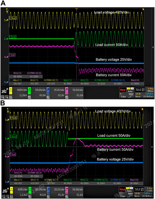
Figure 23. Experimental results when the load steps (A) the load steps from 0 to 6 kW; (B) the load steps from 6 to 0 kW.
From Figure 23B, the system operates smoothly and the load voltage remains stable when the system steps from 6 to 0 kW. Furthermore, when the load is 6 kW, the PV and battery work together to supply the voltage. When the load drops to 0 kW, the PV feeds the battery and the battery is in the charging mode. The proposed mode transition method ensures a smooth transition between these two operational modes.
5 Conclusion
Depending on PV power, load power, and battery status, the system operates in various scenarios, and the control loop may need to change. Because the transition and dynamic processes are difficult to control, implementing control loop switching can be difficult. As a result, this paper presents a generalized mode control method that avoids loop switching in a variety of scenarios.
First, the system structure and topology are introduced, with the common DC-bus structure being used. The operating conditions in grid-connected and off-grid modes are then classified into six scenarios. Furthermore, the control architecture, control loop, and reference transition for various scenarios are discussed. In grid-connected mode, the battery-side DC/DC controls the DC-bus voltage, the PV-side DC/DC uses MPPT mode to maximize PV output power, and the grid-side DC/AC controls the output power. The control loops for DC/DC and Bi-DC/DC do not need to change in different operating scenarios; only the DC/AC output power reference Pref does. Furthermore, Pref equals PPV in scenarios A1 (PPV > PLoad and SOC > 90%) and A4 (PPV ≤ PLoad and SOC ≤ 10%). Pref equals PL in scenarios A2 (PPV > PLoad and SOC ≤ 90%), A3 (PPV ≤ PLoad and SOC > 10%), and A5 (PPV ≤ PPV_min and SOC > 10%). Pref equals zero in scenario A6 (PPV ≤ PPV_min and SOC ≤ 10%). In off-grid mode, the battery-side DC/DC regulates the DC-bus voltage, the PV-side DC/DC uses PPT mode to track the PV output power reference, and the grid-side DC/AC regulates the output voltage. During operating mode switching, only the PV-side DC/DC power reference PPV needs to change; the DC/AC and Bi-DC/DC control loops remain unchanged. PPV equals PL in scenario B1 (PPV > PLoad and SOC > 90%). PPV equals PMPPT in scenario B2 (PPV > PLoad and SOC ≤ 90%) and B3 (PPV ≤ PLoad and SOC > 10%). PV-side DC/DC stops in scenario B5 (PPV ≤ PPV_min and SOC > 10%). In B4 (PPV ≤ PLoad, and SOC ≤ 10%) and B6 (PPV ≤ PPV_min and SOC ≤ 10%) scenarios, the system stops. Finally, an experimental platform is built, and the proposed methodology is validated by the experimental data. According to the experimental findings, there are no surges during mode transitions with the proposed method and seamless transition among operating modes can be achieved.
Data availability statement
The original contributions presented in the study are included in the article/supplementary material, further inquiries can be directed to the corresponding author.
Author contributions
WZ: Writing–original draft, Methodology. YW: Conceptualization, Writing–original draft. PX: Software, Writing–original draft. DL: Supervision, Writing–review and editing. BL: Validation, Writing–original draft.
Funding
The author(s) declare that financial support was received for the research, authorship, and/or publication of this article. This work was funded by Zhejiang Jianbing R&D Program (2024C01242(SD2)).
Conflict of interest
Authors WZ, YW, PX, and BL were employed by Research Center, Ginlong Technologies Co., Ltd.
The remaining authors declare that the research was conducted in the absence of any commercial or financial relationships that could be construed as a potential conflict of interest.
Publisher’s note
All claims expressed in this article are solely those of the authors and do not necessarily represent those of their affiliated organizations, or those of the publisher, the editors and the reviewers. Any product that may be evaluated in this article, or claim that may be made by its manufacturer, is not guaranteed or endorsed by the publisher.
References
Ahmad, K. N. E. K., Selvaraj, J., and Rahim, N. A. (2013). A review of the islanding detection methods in grid-connected PV inverters. Renew. Sustain. Energy Rev. 21, 756–766. doi:10.1016/j.rser.2013.01.018
Aillane, A., Dahech, K., Chrifi-Alaoui, L., Chouder, A., Damak, T., Hadjkaddour, A., et al. (2023). The design and processor-in-the-loop implementation of a super-twisting control algorithm based on a luenberger observer for a seamless transition between grid-connected and stand-alone modes in microgrids. Energies 16, 3878. doi:10.3390/en16093878
Ashabani, S. M., and Mohamed, Y. A. R. I. (2014). New family of microgrid control and management strategies in smart distribution grids—analysis, comparison and testing. IEEE Trans. Power Syst. 29, 2257–2269. doi:10.1109/tpwrs.2014.2306016
Azimi, S. M., and Lotfifard, S. (2021). Supplementary controller for seamless transitions between microgrids operation modes. IEEE Trans. Smart Grid 12, 2102–2112. doi:10.1109/tsg.2020.3049090
Balaguer-Alvarez, I. J., Supatti, U., Rivera, J. G. C., and Peng, F. Z. (2014). Seamless transitions between grid-connected and stand-alone operations of distributed generation in microgrids. Int. J. Eng. Res. Dev. 10, 6–16.
Harirchi, F., Simões, M. G., Babakmehr, M., Al-Durra, A., and Muyeen, S. M. (2015). “Designing smart inverter with unified controller and smooth transition between grid-connected and islanding modes for microgrid application,” in Proceedings of the Industry Applications Society Annual Meeting, Addison, TX, USA, 18–22 October 2015 (IEEE), 1–7.
Hmad, J., Houari, A., Bouzid, A.El M., Saim, A., and Trabelsi, H. (2023). A review on mode transition strategies between grid-connected and standalone operation of voltage source inverters-based microgrids. Energies 16 (13), 5062. doi:10.3390/en16135062
Hwang, T. S., and Park, S. Y. (2013). A seamless control strategy of a distributed generation inverter for the critical load safety under strict grid disturbances. IEEE Trans. Power Electron. 28, 4780–4790. doi:10.1109/tpel.2012.2236578
Jihed, H., Azeddine, H., Hafedh, T., and Mohamed, M. (2019). Fuzzy logic approach for smooth transition between grid-connected and stand-alone modes of three-phase DG-inverter. Electr. Power Syst. Res. 175, 105892. doi:10.1016/j.epsr.2019.105892
Koohi-Kamali, S., and Rahim, N. A. (2016). Coordinated control of smart microgrid during and after islanding operation to prevent under frequency load shedding using energy storage system. Energy Convers. Manag. 127, 623–646. doi:10.1016/j.enconman.2016.09.052
Li, Y., Fu, L., Meng, K., Dong, Z. Y., Muttaqi, K. M., and Du, W. (2020). Autonomous control strategy for microgrid operating modes smooth transition. IEEE Access 8, 142159–142172. doi:10.1109/access.2020.3014255
Liu, Z., and Liu, J. (2014). Indirect current control based seamless transfer of three-phase inverter in distributed generation. IEEE Trans. Power Electron. 29, 3368–3383. doi:10.1109/tpel.2013.2282319
Qinfei, S., Guerrero, J. M., Jing, T., Vasquez, J. C., and Yang, R. (2017). An islanding detection method by using frequency positive feedback based on FLL for single-phase microgrid. IEEE Trans. Smart Grid 8, 1821–1830. doi:10.1109/tsg.2015.2508813
Singh, B., Pathak, G., and Panigrahi, B. K. (2017). Seamless transfer of renewable-based microgrid between utility grid and diesel generator. IEEE Trans. Power Electron. 33, 8427–8437. doi:10.1109/tpel.2017.2778104
Sowa, I., Tran, T. T., Heins, T., Raisz, D., and Monti, A. (2021). An average consensus algorithm for seamless synchronization of andronov-hopf oscillator based multi-bus microgrids. IEEE Access 9, 90441–90454. doi:10.1109/access.2021.3090657
Tran, T.-V., Chun, T.-W., Lee, H.-H., Kim, H.-G., and Nho, E.-C. (2013). PLL-based seamless transfer control between grid-connected and islanding modes in grid-connected inverters. IEEE Trans. Power Electron. 29, 5218–5228. doi:10.1109/tpel.2013.2290059
Yi, Z., Dong, W., and Etemadi, A. H. (2018). A unified control and power management scheme for pv-battery-based hybrid microgrids for both grid-connected and islanded modes. IEEE Trans. Smart Grid 9, 5975–5985. doi:10.1109/tsg.2017.2700332
Zhang, W., Wang, Y., Xu, Po, Li, D., and Liu, B. (2023a). A current control method for grid-connected inverters. Energies 16 (18), 6558. doi:10.3390/en16186558
Keywords: PV, battery, mode control, transition, grid-connected
Citation: Zhang W, Wang Y, Xu P, Li D and Liu B (2024) An operating mode control method for photovoltaic (PV) battery hybrid systems. Front. Energy Res. 12:1435310. doi: 10.3389/fenrg.2024.1435310
Received: 20 May 2024; Accepted: 22 July 2024;
Published: 05 August 2024.
Edited by:
George Tsekouras, University of West Attica, GreeceReviewed by:
Nikolaos Manousakis, University of West Attica, GreeceSridhar Seshagiri, San Diego State University, United States
Copyright © 2024 Zhang, Wang, Xu, Li and Liu. This is an open-access article distributed under the terms of the Creative Commons Attribution License (CC BY). The use, distribution or reproduction in other forums is permitted, provided the original author(s) and the copyright owner(s) are credited and that the original publication in this journal is cited, in accordance with accepted academic practice. No use, distribution or reproduction is permitted which does not comply with these terms.
*Correspondence: Wenping Zhang, d2VucGluZy56aGFuZ0BnaW5sb25nLmNvbQ==
 Wenping Zhang
 Yiming Wang2
 Donghui Li