 Yu Chen
 Yunjian Zhou1,2
 Peihuan Li
- 1CNOOC Research Institute Ltd., Beijing, China
- 2State Key Laboratory of Offshore Natural Gas Hydrates, Beijing, China
- 3China National Oil and Gas Exploration and Development Company Ltd. (CNODC), Beijing, China
- 4SLB Beijing Geoscience Center, Beijing, China
Natural gas hydrates (NGH) are considered a very promising source of clean energy due to their widespread distribution, high energy density, and pure combustion products. Currently, there are few studies on NGH reservoir well testing, and the models are often idealistic, lacking practical guidance for field application. In this paper, a well-testing model for partially perforated wells in the NGH reservoir is proposed, which takes into account the dynamic decomposition of hydrates. This model can simulate the performance of the perforated NGH well with a dynamic dissociation interface, which divides the reservoir into decomposed and undecomposed regions. Governing equations in cylindrical coordinates are formulated to depict fluid flow. Moving boundaries and dissociation coefficients are incorporated to describe the solid-to-gas transition within hydrates. Analytical solutions including the pressure transient behaviors of the NGH reservoir and the bottomhole pressure (BHP) of partially perforated wells are derived by utilizing the Laplace transform method of the separation of variables and the Stehfest numerical inversion algorithm. Sensitivity analysis is conducted using the parameters from partially perforated wells and NGH formation properties. We plot the pressure and pressure derivative curves in double logarithmic coordinates to study the pressure transient behaviors. There are seven flow regimes that are typical for partially perforated wells in the NGH reservoir, namely, pure wellbore storage, skin effect, spherical flow, pseudo-radial flow, composite effect, improvement, and radial flow regimes.
Introduction
Natural gas hydrates (NGH) possess enormous reserves, containing about twice as much carbon as existing fossil fuels (Li et al., 2022). Their combustion generates only a small amount of carbon dioxide and water, resulting in far less pollution than that caused by coal and oil (Liu et al., 2021). With high resource density and widespread global distribution, natural gas hydrates have become an internationally recognized alternative energy source for oil. Since the 1960s, a number of nations have created plans for the exploration and development of natural gas hydrates, including the United States, Japan, Germany, China, South Korea, and India (Zhou et al., 2017). After tight gas, coalbed methane, and shale gas, NGHs gained considerable interest and attention from academicians all over the world, becoming the most potential energy source, with over 230 discovery and production sites worldwide (He et al., 2021).
Recently, significant research has been conducted to evaluate the potential for NGH production. These efforts include reservoir mathematical modeling, exploring, drilling, logging, coring, and testing (Shagapov et al., 2011; Chen et al., 2013; Chandan et al., 2020; Liu et al., 2021; Musakaev et al., 2021; Dong et al., 2022; Wei et al., 2022; Zhu et al., 2023). Among these, well testing is a crucial tool for understanding reservoir dynamics, which can estimate the initial pressure of the reservoir, figure out the fluid flow capacity, assess the extent of the energy action, and estimate the geological reserves of the reservoir or the recoverable reserves of a single well.
Several studies on NGH well testing have been conducted since 2006. A well-testing model for gas reservoirs with hydrate caps was initially put forth by Gerami et al. (2006). In contrast to conventional material balance techniques, this model accounted for the effects of NGH decomposition. The material balance equation was created, and the bottomhole pressure (BHP) and average formation pressure were determined.
Progressing from this point, Gerami et al. (2007) established a mathematical well-testing model for NGH reservoirs with hydrate caps. This model utilized Laplace and Fourier transforms to calculate the dimensionless BHP and described the flow stages of the reservoir.
Then, Kome et al. (2013) established a new well-testing analysis model for natural gas hydrates to study their transient behavior. This model took into account hydrate dissociation, boundary movement, and heat transfer. By integrating the law of conservation of matter and energy and incorporating a heat-transfer model into the diffusion equation, a diffusion model relating to the dynamics of the reservoir was obtained. Analytical solutions for the model were provided under both constant rate and constant pressure conditions.
Based on that, Kome et al. (2014) provided a new insight into the pressure transient behavior research, combining the mass balance equation with a fractional flow equation to study the multiphase fluid diffusivity impact of NGH reservoirs.
Hou et al. (2019) considered factors such as hydrate decomposition, heat transfer, multiphase flow, and multicomponent to show the pressure distribution during NGH reservoir-pressure build-up tests. Based on a two-dimensional cylindrical system, they established a model for vertical wells in type III hydrate reservoirs to analyze hydrate saturation and pressure variations.
An analytical model for vertical wells was developed (Chen et al., 2022) that included a dynamic dissociation interface. The interface radius depended on the decomposition factor and time (Roostaie and Leonenko, 2020). Laplace transforms and Stehfest numerical inversion were used to solve the mathematical model. To comprehend the influence of the decomposition factor, a sensitivity analysis was carried out.
A semi-analytical multi-lateral well model that took into account stress sensitivity and natural gas hydrate dissociation was created (Chu et al., 2023). To find solutions for multi-lateral wells, the superposition method was also used besides Laplace transforms and Stehfest numerical inversion.
Among these NGH well-testing models, most of them were built in a two-dimensional cylindrical system, lacking vertical direction consideration. In addition, the current well-testing models in studies are primarily based on the assumption of a fully penetrating open hole. However, in practical field applications, factors such as well completion methods (e.g., casing perforation) can result in the incomplete opening of the reservoir, leading to the existence of partially perforated wells. Under these conditions, the fluid flow state within the reservoir differs from that of a fully penetrating well. Furthermore, the decomposition of hydrates significantly complicates the flow dynamics within a reservoir, leading to pressure changes, permeability alteration, phase transitions, and so on. A 3D well-testing model for partially perforated wells is proposed in this work. In this model, a dynamic decomposition interface divides the NGH reservoir into two parts: the inner part is a dissociated zone, while the outer part is undissociated. The Laplace transform, method of the separation of variables and Stehfest numerical inversion are used to solve the mathematical model. A sensitivity analysis is carried out in order to evaluate the parameter effects, such as the formation-opening degree, dissociated zone radius, and mobility ratio. This study provides a more comprehensive understanding of well testing in hydrate reservoirs with partially perforated conditions, which is crucial for accurate reservoir evaluation and production optimization.
Physical model
This study establishes a physical model for partially perforated wells in hydrate reservoirs, as shown in Figure 1. The assumptions and considerations of the model are outlined below:
• It is presumed that there is a single-phase, slightly compressible gas flow within the reservoir.
• Gravity, capillary forces, and geothermal gradients are neglected.
• Fluid flow is assumed to follow Darcy’s law.
• The NGH layer is infinite horizontally, and the upper and lower layers are impermeable.
• The vertical well production is carried out at a steady pace. Wellbore storage and skin effect are taken into account.
• An average formation permeability is utilized to replace the permeability anisotropy, as proposed by Spivey and Lee (1998).
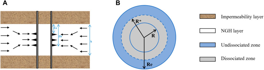
Figure 1. Partially perforated well with dissociation effects in the natural gas hydrate (NGH) reservoir. (A) Side view. (B) Top view.
By considering these assumptions and factors, the model provides a foundation for analyzing well-testing behavior in partially perforated wells within hydrate reservoirs. The effects of various parameters on fluid flow and production performance can be studied, leading to more accurate reservoir evaluation and production optimization strategies.
Mathematical model
Based on the material balance principle, the hydrate diffusion equations at two zones are shown in Eqs 1, 2.
where ψI and ψII represent the pseudo-pressure, r denotes radial distance from the wellbore, z denotes the vertical distance, ϕ denotes the porosity of formation, K denotes the formation permeability, μ is the fluid viscosity, and Ct denotes the compressibility factor. The subscripts I and II indicate the dissociated and undissociated zones, respectively.
The top boundary condition is shown in Eqs 3, 4.
The bottom boundary condition is shown in Eqs 5, 6.
where h denotes the thickness of the reservoir.
The inner boundary condition is shown in Eqs 7, 8
where rw is the radius of the wellbore, q is the gas rate, Bg is the volume factor, and za and zb represent the length from the top boundary to the top or bottom of the perforation, respectively.
The outer boundary condition is shown in Eq. 9
where ψi is the initial reservoir pseudo-pressure.
The interface condition is shown in Eq. 10
where R* is the dynamic dissociation zone radius.
The initial condition is shown in Eq. 11
Dimensionless mathematical Model
The original model can be changed into dimensionless form by introducing the dimensionless variables described in Supplementary Appendix SA1.
The dimensionless governing equations of the two zones are shown in Eqs 12–14
where M12 and w12 denote the mobility ratio and the storativity ratio of the inner-to-outer zones, respectively.
Correspondingly, the boundary conditions and initial conditions can be transformed, as shown in Eqs 15–23
Laplace transform
By applying the Laplace transform to the above equations, the dimensionless governing equations of the two zones are shown in Eqs 24, 25
where u denotes the variable in Laplace space.
The dimensionless boundary conditions in the Laplace domain are shown in Eqs 26–34
For the dynamic interface, according to the model proposed by Goel (2001), R* is related to the time and reservoir properties, as shown in Eq. 35
The gas flow rate at the dynamic interface can be expressed as Eq. 36
After Laplace transformation, the gas flow rate at the dynamic interface can be expressed as Eq. 37
where
Model solution
By applying the separation of variables on Eqs 24, 25, we obtain the following general solutions shown in Eqs 39, 40:
For a formation with both the top and bottom boundaries being impermeable, the β and Zn in the Eqs 39, 40 are expressed as Eqs 41, 42.
When rD approaches infinity,
The process of solving the model is given in Supplementary Appendix SB1. The dimensionless pressure distributions of the NGH formation in Laplace space are expressed as Eqs 43, 44
The dimensionless bottomhole pressure is expressed as Eq. 45
Taking into account the wellbore storage and skin effect (Van, 1949), the bottomhole pressure is expressed as follows equation (Eq. 46):
Results
By performing Stehfest numerical inversion (Stehfest, 1970) on the above solution in the Laplace domain, we obtain its numerical solution. The basic input parameters in the model is shown in Table 1. Then, we plot typical curves for the proposed model and conduct an analysis of the flow characteristics and parameter sensitivity. As shown in Figure 2, the typical curves can be mainly divided into seven flow stages.
(a) Pure wellbore storage regime
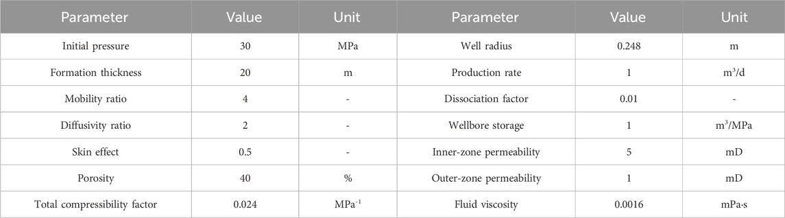
Table 1. Basic input parameters of the model.
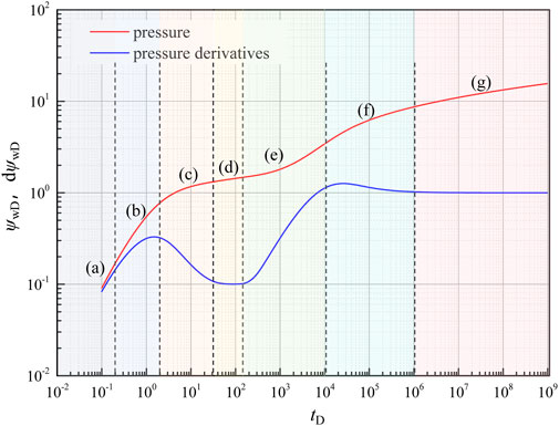
Figure 2. Typical curves of a partially perforated well with dissociation effects in the NGH reservoir.
The pure wellbore storage effect period is indicated in the plot by the merging of the double logarithmic pressure and pressure derivative curves into a single straight line, and the slope of this line is 1.
(b) Skin effect regime
When the fluid around the wellbore flows to the bottomhole, there is an additional pressure drop for a variety of reasons, including formation contamination and perforation. In this stage, the formation conditions in the near-wellbore region are reflected in the curves.
(c) Spherical flow
The fluid in the near-wellbore region flows toward the perforated area, creating spherical flow around the perforations. The pressure derivative curve exhibits characteristics influenced by partial perforation and the permeability ratio.
(d) Pseudo-radial flow
After spherical flow, horizontal pseudo-radial flow is generated in the inner zone, and the dimensionless pressure derivative curve exhibits a typical horizontal straight line.
(e) Composite effect flow
The pressure wave produces a composite effect when it reaches the dynamic interface. The dissociated zone radius affects the start time of the composite effect stage. In addition, the diffusivity ratio difference between the dissociated and undissociated zones influences the curvature of the pressure derivative curve. During this stage, the pressure derivative will deviate more when the diffusivity ratio is higher.
(f) Improvement regime
Following the composite effect stage, the NGH reservoir pressure in the outer region decrease as the pressure wave spreads, resulting in a dissociation of NGH into gas and an increase in fluid flow capacity.
(g) Radial flow
Radial flow occurs in the undissociated zone system, and the pressure derivative curve appears as a horizontal straight line in this period. The entire system reaches a dynamic steady state.
Sensitivity analysis
Effect of the formation–opening degree
Figure 3 shows the influence of the formation–opening degree (LD) on the pressure transient behavior within an NGH reservoir. The formation–opening degree is defined as the thickness ratio of the perforated section to the overall layer, which can influence how easily fluids flow into the wellbore. As LD increases, both the pressure and derivative curves for the skin effect and spherical flow stages trend downward. This implies that the fluid flow into the wellbore becomes easier, which results in a decrease in the pressure drop across the reservoir. This could be due to a larger open area allowing for more flow paths and reducing the concentration of flow near the wellbore.
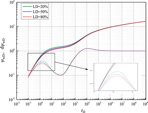
Figure 3. Pressure transient behavior with different formation–opening degrees.
Effect of the radius of the dissociated zone
Figure 4 shows the impact of the dissociated zone radius on the pressure behavior within the NGH formation. As the dissociated zone radius increases, the pressure derivative curve trends to the right, and the pressure curve trends downward. The trends observed suggest that the pseudo-radial flow stage is gradually extended, and the system requires more time to reach the interface due to the larger volume of the dissociated zone. In addition, the appearance time of the composite effect stage is gradually delayed.
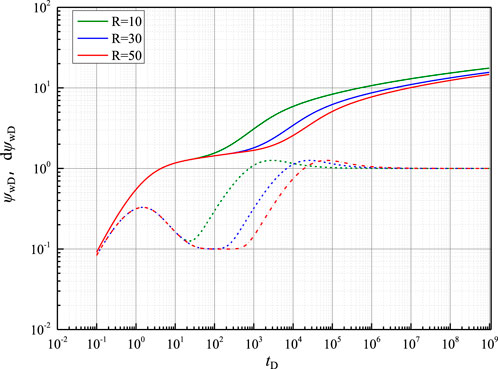
Figure 4. Pressure transient behavior with different radii of the dissociated zone.
Effect of the mobility ratio
Figure 5 shows how the pressure transient behavior changes with different mobility ratios (M12) between the dissociated and undissociated zones. As the mobility ratio increases, both the pressure and derivative pressure curves increase higher during the outer radial flow stage. The slope of the composite effect stage becomes steeper with an increasing mobility ratio, indicating a more rapid change in pressure. Additionally, the figure also shows a significant pressure drop when pressure transfers from the inner to the outer zone. This pressure drop is related to the difference in mobility between the two zones. A higher mobility ratio implies a larger contrast in the fluid flow ability and formation properties within the two zones, which can result in a more abrupt change in pressure as the pressure wave moves through the composite effect stage.
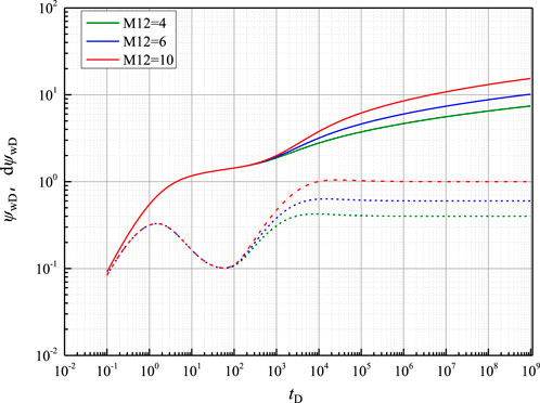
Figure 5. Pressure transient behavior with different mobility ratios between the two zones.
Conclusion
This paper presents a new well-testing model for NGH reservoir development. The proposed model is in a 3D system and takes into account the formation–opening degree of the reservoir and the dynamically decomposing boundary. These features could be significant advancements in the field of NGH testing studies. The model is then discussed and analyzed for sensitivity. The following conclusions are obtained:
(a) Considering the formation–opening degree and NGH decomposition, a well-testing model incorporating the dynamic interface of the hydrate reservoir is established. This model includes seven flow stages: pure wellbore storage, skin effect, spherical flow, pseudo-radial flow in the inner region, composite effect near the interface, improvement, and outer radial flow regime. Among these stages, the pure wellbore storage, skin effect, and spherical flow stages are primarily influenced by NGH well parameters, while the other four stages are mainly influenced by reservoir properties and NGH decomposition.
(b) The spherical flow regime is influenced by the formation–opening degree after the skin effect in the early stage of well testing. A higher degree of formation–opening makes it easier for the fluid to flow into the wellbore, resulting in a decrease in the pressure and pressure derivative.
(c) The pseudo-radial flow regime is mainly affected by the decomposition zone radius. The pressure derivative curve progressively trends to the right as the radius increases, showing an extension of the pseudo-radial flow stage and a delay in the appearance time of the composite effect stage.
(d) As the mobility ratio increases, the pressure curve and its derivative curve become higher at the composite effect stage and outer radial flow stage. This suggests that the fluid flow characteristics of the inner and outer zones differ more, which causes the pressure drop in the undissociated zone to be greater.
The proposed model offers a comprehensive approach to analyze the flow dynamics and pressure behavior within partially perforated hydrate layers. Despite its utility, the model has certain limitations, such as the single-phase flow and the use of average permeability. It employs average permeability to represent both the horizontal and vertical permeabilities. This approach may not fully account for the anisotropic properties of the hydrate layer. Additionally, the NGH decompose and then release gas and water, leading to a complex flow in the reservoir. The assumption of a single-phase flow of gas may not always reflect the multi-phase flow conditions within the NGH layer. Thus, future research will aim to refine the model by considering multi-phase flow and the properties within the reservoir.
Data availability statement
The original contributions presented in the study are included in the article/Supplementary Material; further inquiries can be directed to the corresponding author.
Author contributions
YC: writing–original draft. YZ: formal analysis and writing–original draft. YH: writing–review and editing. QF: writing–review and editing. PL: data curation and writing–original draft. PQ: software and writing–original draft. XF: data curation and writing–original draft.
Funding
The author(s) declare that financial support was received for the research, authorship, and/or publication of this article. This study was supported by the Joint Geological Funds of the National Natural Science Foundation of China (No. U2244223) and National Key R&D Program of China (2021YFC2800905).
Acknowledgments
The authors thank everyone who helped them with this work and give their thanks to the financial support of the Joint Geological Funds of the National Natural Science Foundation of China (No. U2244223) and National Key R&D Program of China (2021YFC2800905).
Conflict of interest
Authors YC, YH, YZ, QF, and XF were employed by CNOOC Research Institute Ltd. Author PL was employed by China National Oil and Gas Exploration and Development Company Ltd.
The remaining authors declare that the research was conducted in the absence of any commercial or financial relationships that could be construed as a potential conflict of interest.
Publisher’s note
All claims expressed in this article are solely those of the authors and do not necessarily represent those of their affiliated organizations, or those of the publisher, the editors, and the reviewers. Any product that may be evaluated in this article, or claim that may be made by its manufacturer, is not guaranteed or endorsed by the publisher.
Supplementary material
The Supplementary Material for this article can be found online at: https://www.frontiersin.org/articles/10.3389/fenrg.2024.1409450/full#supplementary-material
References
Chandan, S., Rajnish, K., and Jitendra, S. (2020). Comprehensive Review on Exploration and Drilling Techniques for Natural Gas Hydrate Reservoirs. Energy Fuels 34 (10), 11813–11839. doi:10.1021/acs.energyfuels.0c02202
Chen, J., Fan, W., Bingham, B., Chen, Y., Gu, L. Y., and Li, S. L. (2013). A long gravity-piston corer developed for seafloor gas hydrate coring utilizing an in situ pressure-retained method. Energies 6, 3353–3372. doi:10.3390/en6073353
Chen, Z., Li, D., Zhang, S., Liao, X., Zhou, B., and Chen, D. (2022). A well-test model for gas hydrate dissociation considering a dynamic interface. Fuel 314, 123053. doi:10.1016/j.fuel.2021.123053
Chu, H., Zhang, J., Zhang, L., Ma, T., Gao, Y., and Lee, W. J. (2023). A new semi-analytical flow model for multi-branch well testing in natural gas hydrates. Adv. Geo-Energy Res. 7 (3), 176–188. doi:10.46690/ager.2023.03.04
Dong, H., Sun, J., Arif, M., Liu, X., Golsanami, N., Yan, W., et al. (2022). A method for well logging identification and evaluation of low-resistivity gas hydrate layers. Pure Appl. Geophys. 179, 3357–3376. doi:10.1007/s00024-022-03120-x
Gerami, S., and Pooladi-Darvish, M. (2006). “Material balance and boundary-dominated flow models for hydrate-capped gas reservoirs,” in SPE 102234, presented at the SPE Annual Technical Conference and Exhibition, San Antonio, Texas, USA, 24–27 September 2006.
Gerami, S., and Pooladi-Darvish, M. (2007). Effect of hydrates on sustaining reservoir pressure in a hydrate-capped gas reservoir. J. Can. Petroleum Technol. 46. PETSOC-07-10-04, Accepted (January 2007) for publication in. doi:10.2118/07-10-04
Goel, N., Wiggins, M., and Shah, S. (2001). Analytical modeling of gas recovery from in situ hydrates dissociation. J. Pet. Eng. 29 (2), 115–127. doi:10.1016/S0920-4105(01)00094-8
He, J., Li, X. S., Chen, Z. Y., Li, Q., Zhang, Y., Wang, Y., et al. (2021). Combined styles of depressurization and electrical heating for methane hydrate production. Appl. Energy 282, 116112. doi:10.1016/j.apenergy.2020.116112
Hou, J., Zhao, E., Liu, Y., Ji, Y., Lu, Nu, Liu, Y., et al. (2019). Pressure-transient behavior in class III hydrate reservoirs. Energy 170, 391–402. doi:10.1016/j.energy.2018.12.178
Kome, M., and Amro, M. (2014). “The impact of multiphase flow on well testing models in gas hydrate reservoirs without crossflow,” in SPE 167682, presented at the SPE/EAGE European Unconventional Resources Conference and Exhibition, Vienna, Austria, February 2014.
Kome, M., Amro, M., and Cinar, Y. (2013). “Analytical models for well test analysis in Class 3 gas hydrate reservoirs,” in Proceedings of: SPE reservoir characterization and simulation conference and exhibition, Abu Dhabi, UAE, September 16-18, 2013.
Li, Q., Zhou, S., Zhao, J., Song, Y., and Zhu, J. (2022). Research status and prospects of natural gas hydrate exploitation technology. Strategic Study CAE 24 (3), 214–224. doi:10.15302/j-sscae-2022.03.022
Liu, J., and Li, X. (2021). Recent advances on natural gas hydrate exploration and development in the South China sea. Energy&Fuels 35 (9), 7528–7552. doi:10.1021/acs.energyfuels.1c00494
Liu, S. (2021). Study on extraction of natural gas hydrate by depressurization combined with in-situ electric heating. Chongqing University. doi:10.27670/d.cnki.gcqdu.2021.001317
Musakaev, N. G., and Borodin, S. L. (2021). Mathematical modeling of the gas hydrate formation process in a zonal heterogeneous porous reservoir. Lobachevskii J. Math. 42, 2205–2210. doi:10.1134/s1995080221090237
Omar, R., Mauro, M., Baumann, C., and Ardila, M. (2016). “Applied buildup well test interpretation: field testing of conventional and deconvolution methods,” in SPE 179008, presented at the SPE International Conference and Exhibition on Formation Damage Control, Lafayette, Louisiana, USA, February 2016.
Roostaie, M., and Leonenko, Y. (2020). Analytical investigation of gas production from methane hydrates and the associated heat and mass transfer upon thermal stimulation employing a coaxial wellbore. Energy Convers. Manag. 209, 112616. doi:10.1016/j.enconman.2020.112616
Sahu, C., Kumar, R., and Sangwai, J. S. (2020). Comprehensive review on exploration and drilling techniques for natural gas hydrate reservoirs. Energy&Fuels 34 (10), 11813–11839. doi:10.1021/acs.energyfuels.0c02202
Shagapov, V.Sh., Khasanov, M. K., Gimaltdinov, I. K., and Stolpovskii, M. V. (2011). Numerical modeling of formation of a gas hydrate in a finite-length porous bed purged by a gas. J. Appl. Mech. Tech. Phys. 52, 599–607. doi:10.1134/s0021894411040134
Spivey, J. P., and Lee, W. J. (1998). “New solutions for pressure transient response for a horizontal or a hydraulically fractured well at an arbitrary orientation in an anisotropic reservoir,” in SPE 49236 Presented at SPE Annual Technical Conference and Exhibition, New Orleans, Louisiana, 27-30 September, 1998.
Spivey, J. P., and Lee, W. J. (2013). Applied well test interpretation. Society of Petroleum Engineers. doi:10.2118/9781613993071
Stehfest, H. (1970). Algorithm 368: numerical inversion of Laplace transforms [D5]. Commun. ACM 13 (1), 47–49. doi:10.1145/361953.361969
Van Everdingen, A. F., and Hurst, W. (1949). The application of the Laplace transformation to flow problems in reservoirs. J. Petroleum Technol. 1 (12), 305–324. doi:10.2118/949305-g
Wei, N., Pei, J., Zhao, J., Zhang, L., Zhou, S., Luo, P., et al. (2022). A state-of-the-art review and prospect of gas hydrate reservoir drilling techniques. Front. Earth Sci. 10. doi:10.3389/feart.2022.997337
Keywords: well testing, natural gas hydrate, partially perforated well, sensitivity analysis, dynamic decomposition
Citation: Chen Y, Zhou Y, He Y, Fu Q, Li P, Qi P and Fang X (2024) A well-testing model for partially perforated wells in natural gas hydrate reservoirs. Front. Energy Res. 12:1409450. doi: 10.3389/fenrg.2024.1409450
Received: 30 March 2024; Accepted: 15 May 2024;
Published: 21 August 2024.
Edited by:
Yan Peng, China University of Petroleum, Beijing, ChinaReviewed by:
Pengliang Yu, The Pennsylvania State University (PSU), United StatesYu Shi, Southwest Jiaotong University, China
Copyright © 2024 Chen, Zhou, He, Fu, Li, Qi and Fang. This is an open-access article distributed under the terms of the Creative Commons Attribution License (CC BY). The use, distribution or reproduction in other forums is permitted, provided the original author(s) and the copyright owner(s) are credited and that the original publication in this journal is cited, in accordance with accepted academic practice. No use, distribution or reproduction is permitted which does not comply with these terms.
*Correspondence: Yufa He, Mjk0MzEwNTk4QHFxLmNvbQ==