 Lin Yang
 Yang Li2*
94% of researchers rate our articles as excellent or good
Learn more about the work of our research integrity team to safeguard the quality of each article we publish.
Find out more
ORIGINAL RESEARCH article
Front. Energy Res. , 08 July 2024
Sec. Sustainable Energy Systems
Volume 12 - 2024 | https://doi.org/10.3389/fenrg.2024.1404462
This article is part of the Research Topic Emerging Technologies for the Construction of Renewable Energy-Dominated Power System View all 32 articles
For the permanent magnet synchronous generator (PMSG) integrated into the flexible interconnected distribution network (FIDN), its low-voltage ride-through (LVRT) strategy needs to be designed to enhance the transient operation capability of the FIDN. The design of the LVRT strategy also needs to take the fault location of the FIDN into consideration. To deal with faults occurring on the integrated feeder of the PMSG, the PMSG needs to realize successful LVRT using the hardware protection equipment. To deal with faults occurring on the feeder adjacent to the integrated feeder of the PMSG, the PMSG needs to release its stored energy to temporarily increase its active power output, which is then supplied to the loads on the faulted feeder that are isolated from the fault through the soft open point (SOP). In this paper, a novel LVRT strategy designed for the PMSG integrated into the FIDN is proposed, which includes dual operation modes that are separately applied to different fault locations. If PMSG is on the faulted feeder, the DC-link voltage of the PMSG is maintained with the controllable resistive fault current limiter (CRFCL), while the maximized stored kinetic energy is reserved to enhance the generation efficiency during the LVRT. If PMSG is on the feeder adjacent to the faulted feeder, the control strategy of the converters of the PMSG is adjusted in response to the power regulation goal at the SOP. Meanwhile, the maximum releasable kinetic energy of the PMSG is considered when increasing its active power output. The feasibility and effectiveness of the LVRT strategy for the PMSG are verified based on the numerical analysis.
With the increasing penetration of distributed generation within the distribution network, the operation state of the distribution network becomes increasingly variable and complicated. Thus, the novel structure of the distribution network incorporating the back-to-back converters, i.e., the flexible interconnected distribution network (FIDN), has attracted great attention with potential for wide-scale application (Ji et al., 2022; Yang et al., 2022; Liu Y. et al., 2023). The FIDN replaces the traditional interconnection switch that links two feeders with the soft open point (SOP). With the SOP, active power exchange between the two feeders can be flexibly controlled. Furthermore, the back-to-back converter at the SOP can provide reactive power to support the terminal voltage of the feeder. The control flexibility brought by the FIDN enhances the capability of distributed power generation integration into the distribution network. For example, the permanent magnet synchronous generator (PMSG) may be connected to the FIDN as part of the wind power integration (Yang et al., 2024; Pradhan et al., 2022). With the integration of distributed wind generation, low-voltage ride-through (LVRT) requirements, traditionally prescribed to wind turbine generators (WTGs) (Yao et al., 2018; He et al., 2020; Xie et al., 2021), become an issue to solve from the operation perspective of the FIDN rather than the WTG alone (Li et al., 2022).
In cases where a fault occurs on the feeder to integrate the PMSG, the PMSG needs to stay connected within the LVRT duration prescribed by grid codes to support the operation of the FIDN (Kim et al., 2013; Wu et al., 2019). To assist the LVRT of the PMSG, usually hardware protection equipment is applied, e.g., the chopper circuit (Xiong et al., 2016; Xing et al., 2018), the series braking resistor (Ji et al., 2014), and the fault current limiter (Huang et al., 2019; Okedu, 2022), to dissipate the redundant active power generation caused by the reduced active power output with the voltage dip at the point of common coupling (PCC) (Huang et al., 2020). The hardware protection scheme is easy to implement but has drawbacks caused by its fixed resistance. For example, multiple switch-ins and -outs of the chopper circuit may occur with inappropriate resistance values, leading to an intensified ripple of the DC-link voltage (Li et al., 2017). For the series braking resistor with comparatively high resistance, overvoltage may occur with minor voltage dips at the PCC (Firouzi et al., 2020). In view of these, the controllable resistive fault current limiter (CRFCL) is a feasible solution to avoid these shortcomings and is capable of providing adjustable resistance values in response to different fault scenarios (Behzad and Negnevitsky, 2015; Huang and Li, 2020). Moreover, instead of dissipating the redundant active power generation in the resistor, the active power output of the machine-side converter (MSC) of the PMSG may be regulated to store the excessive active power generation as the kinetic energy of the rotor (Alepuz et al., 2013; Marmouh et al., 2019). In this way, the generation efficiency of the PMSG during the LVRT may be improved, and the active power reserved may be utilized to provide support to system frequency at the fault-clearance stage (Xiong et al., 2021). In the existing research studies, the variable resistance of the CRFCL is mostly utilized to constrain the fault current during the LVRT. In this case, different levels of resistance values are applied under different voltage drop depths. The resistance of the CRFCL may also be controlled based on simple functions, e.g., the ramp function to realize smooth switch-in and -out of the CRFCL. To further regulate the active power dissipated on the CRFCL during the LVRT, delicate control of the CRFCL resistance is needed, which requires a more complicated control design.
To assist the LVRT of the PMSG, modification to the control of the converter is another widely adopted scheme, apart from hardware protection equipment. To reduce the active power imbalance between the MSC and grid-side converter (GSC), their active power control targets may be switched, i.e., the MSC is responsible for regulating the DC-link voltage during the LVRT (Hanson and Michalke, 2009; Yuan et al., 2009; Yassin et al., 2016). In this way, the active power output from the PMSG may be actively reduced to alleviate the DC-link voltage deviation during LVRT. Still, this scheme retains the outer-loop current control loop, which fails to provide a fast response at the comparatively short LVRT time scale. By eliminating the outer-loop control and applying the direct inner-loop current control (Li et al., 2017), the LVRT performance of the PMSG may be further enhanced.
On the other hand, in cases where the fault occurs on the adjacent feeder connected to the integration feeder of the PMSG through the SOP, the back-to-back converter at the SOP needs to adjust its control strategy to respond to the fault scenario. The converter at the side of the faulted feeder adjusts its current reference to provide the required reactive current injection for the voltage support (Geng et al., 2018; Liu J. et al., 2023) and utilizes the remaining current capacity to maximize the active power output during the LVRT to provide power supply to the loads on the faulted feeder that have been isolated from the fault during the reconfiguration process (Zhou et al., 2021). If the increased active power output is needed by the converter at the side of the faulted feeder, the PMSG at the adjacent feeder may temporarily increase its active power to reduce the transient active power imbalance of the back-to-back converter at the SOP. With the increased active power output, the rotating speed of the shaft is gradually decreasing. For the wind turbine (WT), its rotating speed needs to be regulated so as not to drop below the critical value that causes instability of the WT. Thus, the maximum value of the increased active power needs to be predetermined, and two-mass modeling of the shaft needs to be adopted to ensure a comparatively accurate estimation of the rotating speed of the WT (Yang et al., 2023).
In this paper, the LVRT strategy for the PMSG, especially in the application scenario with integration to the FIDN, is designed with two operation modes corresponding to different locations of the fault. For the fault on the integration feeder of the PMSG, the PMSG utilizes the CRFCL to realize satisfactory LVRT performances under various fault scenarios. The maximized kinetic energy is stored in the rotor with coordinated control between the converters and the CRFCL, which both improves the generation efficiency of the PMSG during the LVRT and reserves active power for the post-fault recovery of the FIDN. For the fault on the feeder adjacent to the integration feeder of the PMSG, the PMSG is controlled to provide active power support to the back-to-back converter at the SOP, in the case where additional active power output is needed at the faulted feeder, to provide power supply to loads isolated from the fault through the process of network reconfiguration. The tow-mass shaft model is adopted to analyze the dynamics of the rotating speed of the WT so as to avoid deacceleration below the critical rotating speed that causes the instability of the WT. Numerical analysis is carried out to verify the feasibility and effectiveness of the proposed LVRT strategy for the PMSG integrated into the FIDN.
The remainder of this paper is organized as follows. The literature review of research related to the LVRT of the PMSG and the FIDN is conducted in Section 1. In Section 2, the configuration of the studied system, i.e., the PMSG-integrated FIDN, is illustrated and modeled. The requirements during the LVRT process are also introduced. In Section 3, the LVRT strategy of the PMSG in the case of faults occurring on the integration feeder is developed. The coordinated control between the CRFCL and converter control is designed to maximize the kinetic energy storage of the rotor during the LVRT process while maintaining the DC-link voltage within security constraints. In Section 4, the LVRT strategy of the PMSG in the case of faults occurring on the adjacent feeder is developed. The control scheme of the PMSG to adjust its active power output based on the power demands of the back-to-back converter and its maximum releasable kinetic energy during the LVRT is presented. The numerical analysis is carried out in Section 5, and the resulting conclusions are presented in Section 6.
The configuration of the FIDN with the integration of the PMSG is illustrated in Figure 1. The feeder that connects the PMSG to the FIDN is denoted as the integration feeder, and the adjacent feeder in the FIDN is connected to the integration feeder through the back-to-back converter at the SOP.
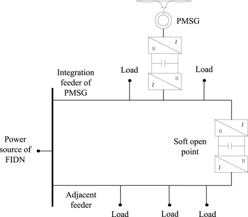
Figure 1. Configuration of the FIDN with the integration of the PMSG.
When faults occur on the integration feeder of the PMSG, the PMSG will suffer from a voltage drop at the PCC. In this case, the PMSG is required to realize LVRT during the fault. Here, the CRFCL is implemented at the stator side of the PMSG to dissipate the power imbalance between the MSC and GSC, as illustrated in Figure 2. Usually, the fault current limiter (FCL) is placed at the generator terminal to elevate the terminal voltage. Yet, in the case of the PMSG, the fault is partially isolated by the back-to-back converter, and the key to a successful LVRT is to mitigate the transient active power imbalance between the MSC and GSC. In view of this, the CRFCL is directly placed on the MSC side to dissipate the redundant active power output from the PMSG. Another choice to implement the CRFCL is to connect it to the DC-link capacitor to operate as the DC chopper circuit. However, the DC chopper circuit is a comparatively passive protection scheme that requires the DC-link voltage to reach its constraint in the first place. Thus, installing the CRFCL as the DC chopper circuit fails to fully utilize the controllability of the CRFCL.

Figure 2. PMSG with implemented CRFCL at the stator side to assist the LVRT.
The resistance of the CRFCL is controllable. When a fault occurs on the adjacent feeder, its resistance is reduced to zero, while the PMSG adjusts its active power output, which is transferred to the adjacent feeder through the SOP.
For the PMSG, when assuming that its flux is aligned to the direct axis, the stator flux of the PMSG and its dynamic adopting the generator convention are modeled using Eq. 1.
where ψ, L, I, V, and R are the flux, inductance, current, voltage, and resistance, respectively; p is the differential operator; ψf is the flux of the permanent magnet; ωr is the rotor speed; the subscript s denotes the stator; and subscripts d and q denote the direct and quadrature axes, respectively.
If the d-axis inductance of the stator is equal to its q-axis inductance, the steady-state output active power of the stator and the electromagnetic torque of the PMSG are derived based on Eq. 1, which is given by Eq. 2.
where Ps is the active power of stator and Te is the electromagnetic torque of the PMSG.
It can be seen from Eq. 2 that the active power output of the PMSG is approximately proportional to the q-axis stator current, based on which the traditional dual-loop PI control schemes of the MSC and GSC are developed and illustrated in Figure 3, where subscripts PCC, dc, and g denote the point of common coupling, the DC-link capacitor, and the GSC, respectively; superscript ref denotes the reference value, and ω0 is the synchronous electric angular speed of the power system.
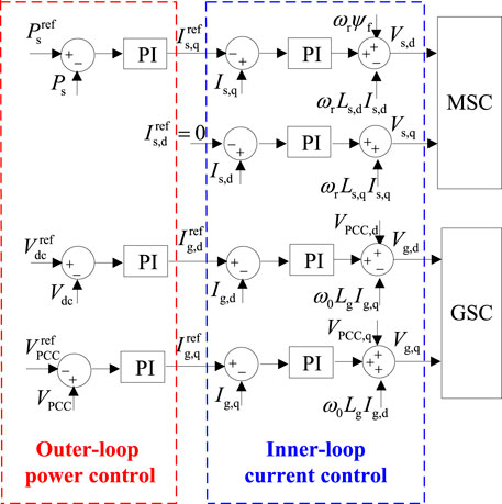
Figure 3. Traditional dual-loop PI control schemes for MSC and GSC.
For the MSC, since the stator output active power is approximately proportional to the q-axis stator current, the reference of the q-axis stator current is yielded by the outer-loop power control. On the other hand, for the GSC, its active power outer-loop control is responsible for the DC-link voltage regulation, and its reactive power outer-loop control is responsible for maintaining the PCC voltage (Xiong et al., 2020). Current references proportional to the active and reactive power output of the GSC are prescribed by the outer-loop power control and applied for the inner-loop current control.
As for the CRFCL, its equivalent resistance at the AC side is determined by the resistance value of the resistor placed at the DC side and the duty ratio of the switching signals applied to the parallel connected switch, as given by Eq. 3 (Behzad and Negnevitsky, 2015). Through control of the duty ratio of the switching signal, the CRFCL is capable of providing variable resistance. The switching signal is generated using the pulse width modulation (PWM) technique. To realize effective control over the equivalent resistance of the CRFCL, the frequency of the PWM signal does not need to be set to a high value. The frequency of the PWM signal is set to 500 Hz for the studied system illustrated in Figure 2.
where RCRFCL is the equivalent resistance of the CRFCL, D is the duty ratio of the switching signal, and RDC is the resistance value of the resistor at the DC side.
The designed LVRT scheme applies different strategies, with faults occurring at the integration and adjacent feeders, as shown in Figure 1, respectively. The controller collects protection information from the feeders to identify fault locations. With faults occurring on the integration feeder, the controller aims to ensure successful LVRT of the PMSG, and the active power output of the PMSG is reduced to avoid overvoltage of the DC-link capacitor. However, with faults occurring on the adjacent feeder, the active power output of the PMSG is increased to provide power supply through the soft open point to load nodes on the faulted feeder that have been isolated from the fault.
With faults occurring on the integration feeder, the coordinated operation of the converter control and the CRFCL come into action to assist the LVRT of the PMSG. Considering the short time scale of the LVRT transient, the single inner-loop current control scheme is applied to both the MSC and GSC in the modified converter control scheme to enhance the LVRT capability of the PMSG, as illustrated in Figure 4. The elimination of the outer-loop power control enables the converter to provide a faster response to the LVRT needs compared to the traditional dual-loop control scheme. To achieve the same control target, the current references need to be calculated based on the parameters of the outer-loop power control and then applied to the direct inner-loop current control, as given by Eq. 4.
where kPCC is the voltage dip depth at the PCC and subscript m denotes the MSC.
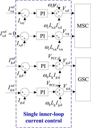
Figure 4. Modified converter control scheme for enhanced LVRT capability of the PMSG.
One of the essential functions of the outer-loop power control is to maintain the DC-link voltage, which is a key requirement for successful LVRT and needs to be retained by setting up connections between the active current references of the MSC and GSC to indirectly maintain the active power balance. However, this balance is difficult to maintain since the active power output capability of the GSC is constrained by the voltage dip at the PCC. With severe voltage dips, assistance from the CRFCL is needed to dissipate the redundant active power from the stator.
The dynamic DC-link voltage of the PMSG is given in Eq. 5. For the GSC, its maximum active power output during the LVRT is determined by the remaining capacity of the GSC after the GSC injects reactive current to the PCC based on the voltage dip depth, as given by Eq. 6.
where C is the DC-link capacitance and the superscript max denotes the maximum feasible value.
With the CRFCL resistance taken into consideration, the input active power of the MSC is quantified using Eq. 7.
Combining Eqs 6, 7, the maximum variation in the stored energy in the DC-link capacitor during the LVRT yielded by the active power imbalance between the MSC and GSC is given by Eq. 8.
where ΔE is the maximum variation in the stored energy and tf is the duration of the LVRT process.
As can be seen from Eq. 8, to solve ΔE, the integral of the rotor speed, i.e., the variation in the rotor speed during the LVRT duration, is needed. With the one-mass modeling of the PMSG shaft, i.e., the rotating speed of the PMSG rotor is equal to that of the WT, variation in the rotor speed is modeled using Eqs 9, 10. To solve the differential equation, the improved Euler method is applied to solve the rotor speed dynamic during the LVRT.
where Heq is the equivalent inertia time constant of the PMSG shaft, PWT is the mechanical power captured by the WT, ρ is the air density, vw is the wind speed, c1–c9 are parameters of the Cp function, λ is the tip speed ratio, λi is the intermediate variable, ωWT is the rotating speed of the WT, and r is the radius of the WT.
The process of solving Eq. 9 using the improved Euler method is given by Eq. 11, where Δt is the time step adopted to solve the rotating speed dynamic; superscripts (n) and (n+1) denote the values at the beginning and ending instants of the nth time step, respectively; and the superscript pred denotes the prediction value obtained with the Euler method.
In some cases, the variation in the mechanical power captured by the WT is ignored for the LVRT duration. This assumption is acceptable with no change to the active power control scheme of the MSC. As for the LVRT scheme in this paper, the active power of the stator is adjusted and the rotating speed of the WT varies with the significant change in the stored kinetic energy; thus, in this case, the impact of the rotating speed change on the mechanical power of the WT may not be ignored.
When solving the rotor dynamic during the LVRT based on Eqs 9, 10, the pitch angle of the WT is considered to be constant due to the short time scale of the LVRT duration. The allowable change rate of the pitch angle is usually constrained below 2° per second. With the limited response capability of the pitch angle regulation and further considering the postponed response due to control delay, the impact of the pitch angle regulation is ignored here to realize higher calculation efficiency without affecting the accuracy of the calculation results.
Considering the upper limit of the DC-link voltage, the maximum value of the stored energy variation is quantified using Eq. 12.
where Vdc,upper and Vdc,ini denote the upper limit and the initial value of the DC-link voltage, respectively.
To realize successful LVRT of the PMSG, the key is to constrain the DC-link voltage within its security constraint. Based on calculations with Eqs 5–12, the DC-link voltage variation with the setting of the q-axis stator current reference is obtained to check its voltage constraint, and the required minimum CRFCL resistance to avoid the overvoltage of the DC-link can be determined. Meanwhile, the acceleration of the PMSG rotor may also cause violations of the upper constraint of the rotor speed. In that case, a larger reference of the q-axis stator current needs to be applied to increase the electromagnetic torque of the PMSG.
As can be seen from Section 3.1, the current references of the converter control and the resistance of the CRFCL both affect the LVRT transient; thus, they need to be applied in a coordinated manner to realize the optimal LVRT effect. The optimization targets for the coordinated control are set to first maximize the kinetic energy stored in the PMSG rotor and then minimize the resistance of the CRFCL to reduce the active power dissipated in the resistor. The flowchart of the coordinated operation of the CRFCL and the converter control is shown in Figure 5.
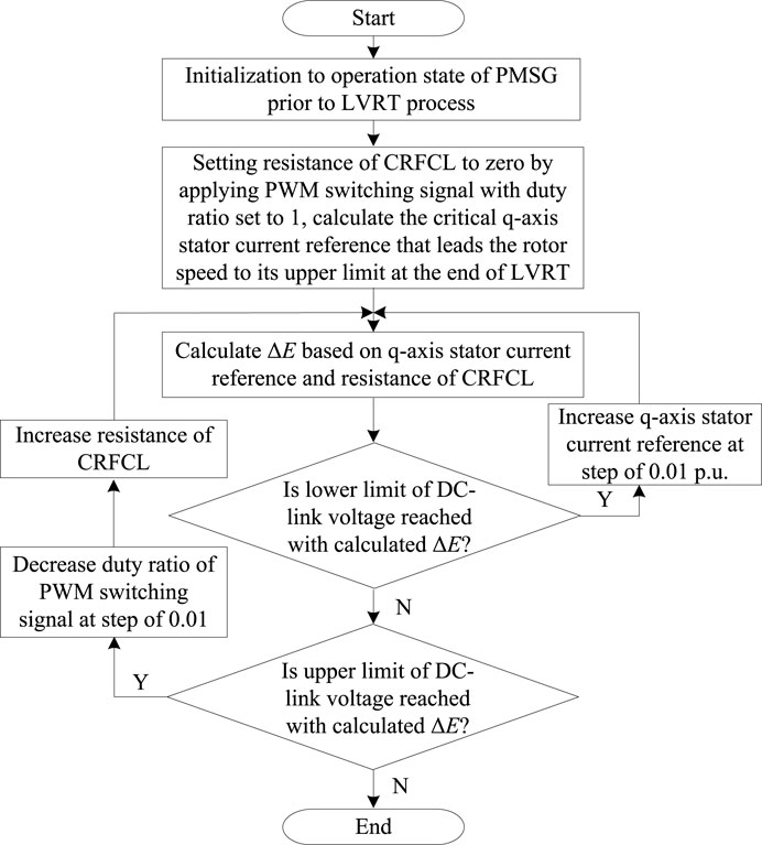
Figure 5. Coordinated operation of CRFCL and converter control with faults on the integration feeder.
As shown in Figure 5, first, the initial operation state of the PMSG needs to be solved. The PMSG may operate in the maximum power point tracking (MPPT) or power dispatch mode. The initialization of the PMSG under these two modes may be referred to in Li (2015). Normally, under the power dispatch mode, the operation point of the PMSG drifts away from the MPPT point to realize active power reserve for frequency regulation. If the overspeed control is adopted to reserve active power, the capacity of the kinetic energy that can be stored in the PMSG rotor will be decreased compared to the case of MPPT operation.
Based on the initial operation state, the critical q-axis stator current that leads the rotor speed to its upper limit at the ending instant of the LVRT duration, with the resistance of the CRFCL controlled to zero, is first determined. This q-axis stator current corresponds to the ideal LVRT transient, where the theoretical maximum kinetic energy is stored and no active power is dissipated in the CRFCL resistance. The variation in the DC-link voltage is then evaluated, and if the voltage constraint of the DC-link is violated, the q-axis stator current reference and the resistance of the CRFCL are correspondingly readjusted to ensure the successful LVRT of the PMSG.
If the prescribed q-axis stator current reference and CRFCL resistance yield an undervoltage of the DC-link, the active power output of the MSC needs to be increased by increasing the q-axis stator current reference. This situation may occur with minor voltage drops where the comparatively small value of the reactive current injection is required and a large amount of active current is provided to the integrated grid, and the undervoltage of the DC-link will occur as the active power originally transmitted to the MSC now transforms into kinetic energy stored in the PMSG rotor.
In the other case, with the overvoltage of the DC-link, the active power imbalance may not be compensated merely through storing kinetic energy in the PMSG rotor; thus, the resistance of the CRFCL is increased to dissipate part of the active power imbalance. With the scheme of the CRFCL resistance control shown in Figure 5, the minimum resistance of the CRFCL is determined to minimize the transient active power consumption of the CRFCL during the LVRT. In this way, the active power loss is minimized.
After the fault clearance, the PMSG needs to realize a quick recovery to its initial operation state prior to the LVRT process. To realize the quick recovery of the DC-link voltage to its nominal value, the output of the integral link with the DC-link voltage difference as the input is adjusted to ensure that the q-axis stator current reference is set to its pre-fault value at the initial fault clearance stage. In this way, the active power imbalance between the MSC and GSC will be minimized as the PMSG enters the fault clearance stage. Then, using the outer-loop DC-link voltage control, the DC-link voltage may be quickly controlled to its nominal value.
With faults occurring on the feeder adjacent to the integration feeder of the PMSG, first, the converters at the SOP need to respond to this LVRT scenario. For the back-to-back converters at the SOP, the converter at the PMSG side is denoted with the subscript int and the converter at the adjacent feeder is denoted with the subscript adj in this section. With the voltage dip depth kadj at the adjacent feeder, the active power reference of the connected converter during the LVRT, Padj, LVRT, is given by Eq. 13 in a similar manner to the transient LVRT control of the PMSG. The connected converter injects reactive current proportional to the voltage drop depth, and the remaining current capacity is utilized for the transient active power output.
Meanwhile, the converter at the PMSG side is currently responsible for maintaining the DC-link voltage at the SOP; thus, the additional active power need, ΔPint, is incorporated into its outer-loop active power control based on the calculation of the increased active power output of the converter at the adjacent feeder side, as given by Eq. 14. The additional active power need is added as a compensation term to the output of the outer-loop PI control with the input of the DC-voltage control difference to ensure the quick response of the active control by the converter at the PMSG side.
The increased active power demand from the converter at the integration feeder side may be partially or completely provided by the PMSG by releasing the kinetic energy in the PMSG rotor during the LVRT transient. Through the deacceleration process to release the kinetic energy of the PMSG, the rotating speed of the WT needs to be maintained above the critical value ωWT,cri to prevent instability of the PMSG shaft, as shown in Figure 6.
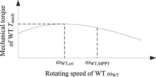
Figure 6. Critical rotating speed of the WT corresponding to the instability of the PMSG shaft.
As can be seen from Figure 6, the value of the critical rotating speed of the WT is smaller than its value corresponding to the MPPT operation mode ωWT,MPPT. At the critical rotating speed, the derivative of the mechanical torque of the WT to its rotating speed is zero. Thus, the critical rotating speed may be obtained by solving the mathematical equation given in Eq. 15.
Once the rotating speed of the WT drops below the critical value, the mechanical torque of the WT also decreases, making the PMSG unable to recover to its initial operation state. Thus, increased active power output from the PMSG, ΔPm, must be constrained to maintain the rotating speed of the WT above its critical value.
It should be noted that the mechanical power captured by the WT needs to be modeled based on the detailed Cp function, as given by Eq. 10, to solve Eq. 15, despite the complexity involved in the calculation process. One classically simplified model assumes that the mechanical power of the WT is proportional to the cube of the rotating speed, but this assumption is only valid for MPPT operation. As shown in Figure 6, at the critical rotating speed, the WT does not work under the MPPT mode; thus, the simplified model cannot be applied here.
As stated in Section 4.1, the rotating speed of the WT needs to be maintained above its critical value when releasing the kinetic energy; thus, the two-mass shaft model is adopted to analyze the dynamic rotating speed of the WT to achieve higher accuracy and eventually obtain an appropriate reference for the increased active power output of the PMSG during the LVRT.
With the increased active power reference of the PMSG, the rotating speeds of the WT and the rotor may be analyzed based on the two-mass shaft model, as given in Eq. 16. The two-mass model of the PMSG shaft is illustrated in Figure 7. The different inertias of the WT and PMSG rotors are considered in the two-mass model. When increasing the active power output of the PMSG, the electromagnetic torque increases, and the PMSG rotor quickly decreases due to its comparatively smaller inertia. As shown in Eq. 2, the active power control of the PMSG is affected by its rotor speed, and the improved accuracy of rotor speed modeling based on the two-mass shaft is beneficial to the transient power control of the PMSG.
where H is the inertia time constant; Ds and Ks are constant coefficients describing the damping and stiffness of the shaft, respectively (Han et al., 2011; Mandic et al., 2012); and γ is the torsional angle of the shaft. With a larger stiffness coefficient, the torque generated by the torsional angle resulting from the difference between the rotating speeds of the WT and PMSG rotors will be increased, i.e., their difference tends to be decreased. On the other hand, with the larger damping coefficient, a similar damping torque is increased, also to reduce the difference between the rotating speeds of the WT and PMSG rotors. In conclusion, with the larger stiffness and damping coefficient, the two-mass shaft will behave more like the one-mass shaft.
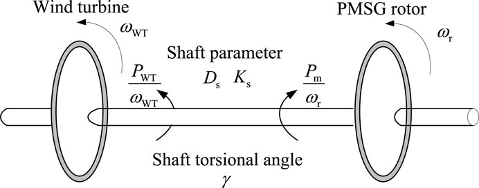
Figure 7. Two-mass model of the PMSG shaft.
With the improved Euler method applied to solve the differential equations in Eq. 16, the rotating speed of the WT at the ending instant of the LVRT process with increased active power output of the PMSG is calculated. Based on the calculation results, the maximized active power support capability of the PMSG is determined to obtain the appropriate active power reference during the LVRT. The solving process of Eq. 16 using the improved Euler method is given by Eq. 17. The flowchart describing the detailed LVRT scheme procedure is shown in Figure 8.
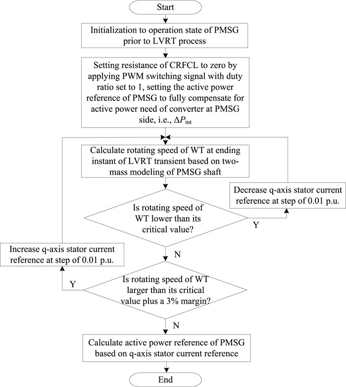
Figure 8. Flowchart to determine the active power reference of the PMSG with faults on the adjacent feeder.
As shown in Figure 8, the initial active power setting applied to the PMSG is intended to fully compensate for the active power demand from the converter at the PMSG side of the SOP. However, if the calculation of the rotating speed of the WT based on the two-mass model indicates that the instability of the WT will occur with its rotating speed dropping below the critical value, the q-axis stator current reference is reduced to decrease the active power output of the PMSG to the optimal value that both fully utilizes the stored kinetic energy of the PMSG to provide active power support during the LVRT and prevents instability of the PMSG at the same time to enable the PMSG to recover to its initial operation state after the LVRT transient. In Figure 8, the q-axis stator current reference is adjusted to ensure that, at the end of the LVRT duration, the rotating speed of the WT is maintained above its critical value with a plus 3% margin, taking into account the calculation error caused by the improved Euler method to solve the differential equation, as well as the neglection of the pitch angle variation. To further ensure that the instability of the PMSG shaft will not occur, a backup protection scheme is employed that reduces the active power control goal of the PMSG to 80% of the current value of mechanical power captured by the WT, once the rotating speed approaches the critical value, to prevent further dropping of the rotating speed.
To maintain the rotating speed of the WT above its critical value, the speed control of the PMSG may be applied to replace the active power control of the MSC. This scheme is not adopted here for the following two reasons: on one hand, this scheme still contains the outer-loop PI control; thus, it may not provide a fast response during the LVRT transient. On the other hand, the parameters of the speed control require careful tuning to avoid the rotor speed dropping below its critical value during the control transient.
The detailed parameters of the PMSG used for the simulation analysis are provided in Table 1. The parameters of the Cp function are referred to in Li (2015). As for the LVRT analysis, the fault occurs at t = 0.1 s and lasts for 0.625 s.
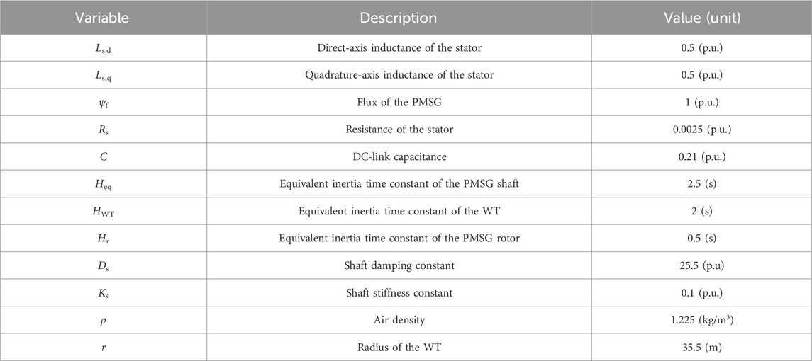
Table 1. Parameters of the PMSG (Huang et al., 2021).
In this section, the effectiveness of the LVRT strategy with faults occurring on the integration feeder of the PMSG is verified.
During the LVRT, the output active power of the GSC is reduced according to grid code requirements and the voltage dip depth, as given by Eq. 6. In this subsection, a minor voltage dip under a wind speed of 9 m/s is considered, and in this case, the active power output of the GSC is reduced to 70% of its pre-fault value. The calculated q-axis stator current that leads the rotating speed of the WT to its maximum value is 0.9 p. u., and no CRFCL resistance is applied. The transient q-axis stator current, rotating speed of the WT, and DC-link voltage are shown in Figure 9.
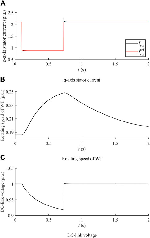
Figure 9. LVRT transient under a minor voltage dip with no CRFCL resistance. (A) q-axis stator current. (B) Rotating speed of the WT. (C) DC-link voltage.
The quick response of the inner-loop current control is verified based on the transient stator q-axis current shown in Figure 9A. The q-axis stator current is capable of tracking its reference within a short duration of time, which enhances the transient active power control capability of the PMSG. Figure 9B shows that the calculated q-axis stator current reference can maximize the kinetic energy stored in the WT during the LVRT. With a minor voltage dip, the active power imbalance is comparatively small and can be solely compensated with kinetic energy stored in the WT. The reduced active power output of the MSC yields the voltage drop of the DC-link, as shown in Figure 9C. Generally, the DC-link voltage should not fall below 0.95 p. u. The setting value of the allowable DC-link voltage drop (0.05 p. u.) is smaller than that of the allowable DC-link voltage increase (0.2 p. u.) as the converter voltage control will be affected by the undervoltage of the DC-link. In this case, the q-axis stator current reference may be increased to the value that yields smaller deviations of the DC-link voltage.
By increasing the q-axis stator current reference, the power transmitted to the MSC is increased to reduce the deviation of the DC-link voltage. With the q-axis stator current reference increased to 1.25 p. u., the active power input of the MSC is increased, and the increment of the rotating speed during the LVRT is reduced due to the increased active power. Meanwhile, the undervoltage of the DC-link is avoided, with the DC-link voltage maintained close to its nominal value during the whole LVRT process, as verified by the results shown in Figure 10.

Figure 10. LVRT transient under a minor voltage dip with the DC-link voltage maintained close to the nominal value. (A) Rotating speed of the WT. (B) DC-link voltage.
As the q-axis stator current reference further increases, the active power output of the MSC is also increased, and the upper limit of the q-axis stator current reference is reached once the DC-link voltage reaches its maximum feasible value at the ending instant of the LVRT transient, as shown in Figure 11.
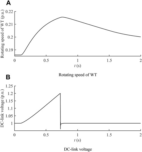
Figure 11. LVRT transient under a minor voltage dip with the maximum q-axis stator current reference. (A) Rotating speed of the WT. (B) DC-link voltage.
As shown in Figure 11B, with the q-axis stator current reference increased to 1.4 p. u., the upper limit of the DC-link voltage is reached, which denotes the maximum active power output capability of the MSC during the LVRT. Figure 11A shows that, under the minor voltage drop, the active power output of the MSC can be increased to enhance the active power support capability of the PMSG, as long as the DC-link voltage does not increase above its upper constraint, instead of utilizing the full capacity of kinetic energy storage of the WT to reduce the active power imbalance between the MSC and GSC.
In this subsection, a severe voltage dip under the wind speed of 9 m/s is considered, and in this case, the active power output of the GSC is reduced to 20% of its pre-fault value. The calculated q-axis stator current that leads the rotating speed of the WT to its maximum value is 0.98 p. u. However, with the greatly reduced active power output of the GSC under the severe voltage dip, the active power imbalance between the MSC and GSC needs to be partially dissipated in CRFCL resistance to avoid the overvoltage of the DC-link. The calculation result of the optimal CRFCL resistance in this case is 0.1 p. u. The comparison between different CRFCL resistances, as displayed in Figure 12, shows that the optimal resistance can avoid the overvoltage of the DC-link while minimizing the active power dissipated in the CRFCL resistance at the same time.
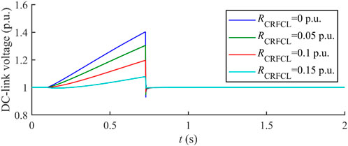
Figure 12. Comparison of transient DC-link voltage with different CRFCL resistance values.
With the active power output of the GSC further dropping from 20% of its pre-fault value to 0% of its pre-fault value (0.078 p. u. to 0 p. u.), the active power imbalance between the MSC and GSC is increased; thus, the required CRFCL resistance to maintain the DC-link voltage within security constraints is increased alongside, as revealed by the optimal CRFCL resistance values with the decreasing active power output of the GSC during the LVRT shown in Figure 13.
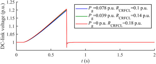
Figure 13. Optimal CRFCL resistance with different active power output values of the GSC during the LVRT.
In this subsection, a severe voltage dip is considered, and in this case, the active power output of the GSC is reduced to 0% of its pre-fault value. Different wind speeds are considered, and with each wind speed, the q-axis stator current reference and the optimal CRFCL resistance are obtained based on the procedure illustrated in Figure 5. The transient rotating speed of the WT and DC-link voltage under different wind speeds with optimized q-axis stator current reference and CRFCL resistance are shown in Figure 14.
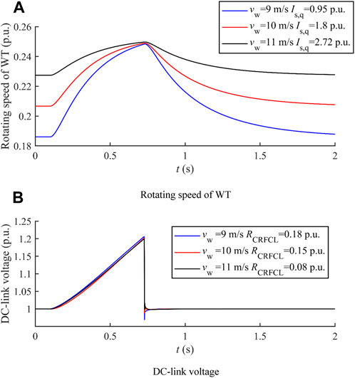
Figure 14. LVRT transient with optimized q-axis stator current and CRFCL resistance under different wind speeds. (A) Rotating speed of the WT. (B) DC-link voltage.
Figure 14A shows that the initial rotating speed of the WT is higher at high wind speeds; thus, the capacity for kinetic energy storage is smaller. In this case, the optimal q-axis stator current reference is increased to provide larger electromagnetic torque so as to avoid the overspeed of WT. Meanwhile, the optimal q-axis stator current reference is capable of fully utilizing the available capacity for kinetic energy storage as the rotating speeds of the WT all approach their upper limit under the different wind speeds. Based on the optimal q-axis stator current references, corresponding CRFCL resistance values that avoid overvoltage of the DC-link with the minimized active power consumed by the CRFCL are determined, and their effectiveness under different wind speeds is verified, as shown in Figure 14B.
In this section, the effectiveness of the LVRT strategy with faults occurring on the feeder adjacent to the integration feeder of the PMSG is verified.
With faults occurring on the adjacent feeder, the PMSG may provide active power support to the adjacent feeder through SOP during the LVRT. It needs to be ensured that, with an increased active power output of the PMSG, the rotating speed of the WT will not drop below the critical value related to shaft instability. Under wind speed 11 m/s, through a calculation based on the flowchart shown in Figure 8, it is determined that the maximum increase in the active power output of the PMSG during the LVRT duration (0.1 s–0.725 s) is 0.1 p.u. The transient rotating speeds of the WT and the rotor with different active power increments are compared in Figure 15.
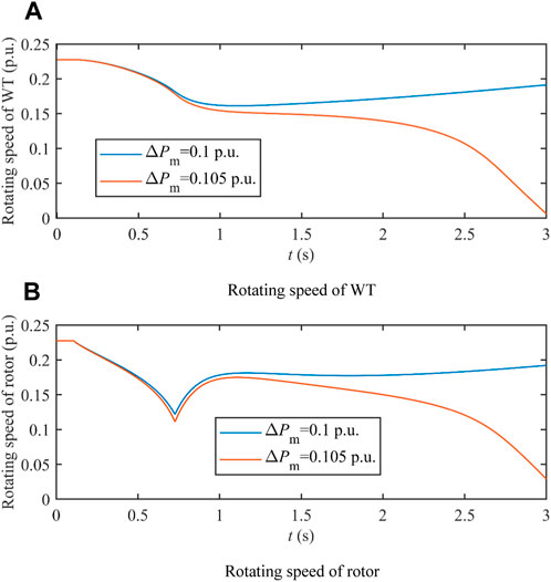
Figure 15. Transient rotating speeds of the WT and rotor with different active power increments. (A) Rotating speed of the WT. (B) Rotating speed of the rotor.
The correctness of the calculated maximum active power increment of the PMSG (0.1 p.u.) is verified by the results shown in Figure 15. Even with the slightly larger active power increase (0.105 p.u.), the WT will deaccelerate to a rotating speed smaller than its critical value; thus, the WT keeps deaccelerating even after the active power output of the PMSG recovers to its pre-fault value.
As can be seen from Figure 15, the transient rotating speeds of the WT and rotor are different due to their different inertia and the stiffness and damping of the shaft. Given that the instability of the PMSG shaft is closely related to the rotating speed of the WT, the two-mass model of the shaft is capable of providing more accurate results of the rotating speeds of the WT and rotor. In this subsection, the necessity of adopting two-mass modeling is further verified. With the active power increment of the PMSG set to 0.105 p.u., the previous results shown in Figure 15 indicate that instability of the PMSG shaft will occur with analysis based on the two-mass model of the shaft. With the one-mass model of the shaft, the result of the rotating speed of the WT is shown in Figure 16, in comparison to results based on the two-mass model.
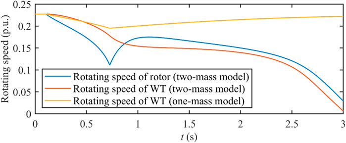
Figure 16. Rotating speeds of WT and the rotor with a 0.105 p. u. active power increment based on one-mass and two-mass modeling.
Figure 16 shows that, with the one-mass model, instability of the PMSG shaft will not occur. This is because the one-mass model combines the WT with the larger inertia and the rotor with the smaller inertia; thus, the rotor speed change is underestimated by the one-mass model. With the smaller inertia, a rotor speed deaccelerates at a faster speed. With the smaller rotor speed, the larger electromagnetic torque is required to maintain the active power output of the PMSG, which further leads to the deacceleration of both the WT and rotor. Based on the results shown in Figure 16, with the one-mass modeling of the PMSG shaft, the optimistic result of the deacceleration with the active power output increment is yielded, failing to prevent instability issues with the PMSG shaft. The results in Figure 17 show that, with the one-mass model of the shaft, it is estimated that instability of the shaft will occur until the active power increment increases to approximately 0.22 p.u., which is far larger than the result obtained based on the more accurate two-mass modeling (0.105 p.u.), showing the necessity to incorporate two-mass shaft modeling.
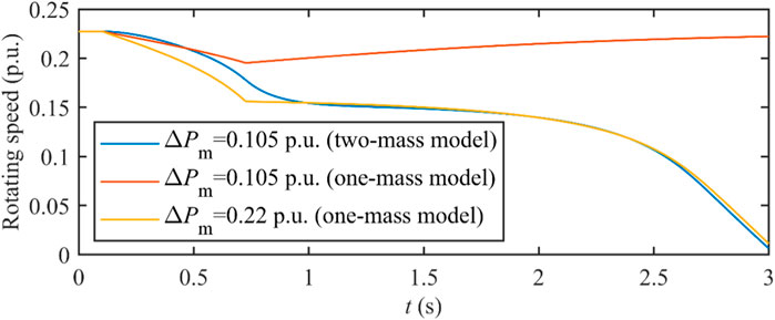
Figure 17. Evaluation results of the maximum active power output increment with different shaft models.
In this paper, the LVRT strategy for the PMSG integrated into the FIDN is designed considering faults occurring on different feeders. With faults on the integration feeder of the PMSG, a coordinated scheme between control to the converters and CRFCL is developed, which is capable of realizing optimization targets, including storing imbalanced active power as kinetic energy of the PMSG, maintaining the DC-link voltage within its security constraints, and minimizing the active power dissipated in CRFCL resistance. With faults occurring on the feeder adjacent to the integration feeder of the PMSG, active power support is provided by the PMSG if needed, and the scheme to determine the maximum active power support capability is designed to avoid the instability of the PMSG shaft resulting from constant deacceleration. Based on the results of the numerical analysis, the following conclusions are drawn:
(i) During the LVRT with faults on the integration feeder of the PMSG, through optimization of its q-axis stator current reference, the capability of the PMSG to store the imbalanced active power as kinetic energy is fully utilized with the rotating speed of the WT controlled to its maximum value at the ending instant of the LVRT transient.
(ii) During the LVRT with faults on the integration feeder of the PMSG, through optimization of the resistance of the CRFCL, the minimized CRFCL resistance needed to keep the DC-link voltage within its security constraint is obtained to realize a successful LVRT with the minimum active power loss on the CRFCL.
(iii) During the LVRT with faults on the adjacent feeder, the maximum active power increment of the PMSG is determined based on the two-mass modeling of the shaft, which ensures that the rotating speed of the WT is kept within the stable operation range during the LVRT transient.
The raw data supporting the conclusion of this article will be made available by the authors, without undue reservation.
LY: conceptualization, data curation, and writing–original draft. YL: conceptualization, project administration, resources, software, and writing–review and editing. YZ: data curation, formal analysis, investigation, methodology, and writing–review and editing. ZX: methodology, project administration, resources, and writing–review and editing. JC: data curation, investigation, resources, and writing–review and editing. YQ: resources, validation, and writing–review and editing. GS: writing–review and editing, methodology, validation, investigation.
The author(s) declare that financial support was received for the research, authorship, and/or publication of this article. This work is supported by the Science and Technology Project of Xingyi Power Supply Bureau of Guizhou Power Grid Co., Ltd (0606002023030103JH00011).
Authors LY, YL, and ZX were employed by Xingyi Power Supply Bureau of Guizhou Power Grid Co., Ltd.
Authors YZ, JC, and YQ were employed by Guizhou Power Grid Co., Ltd.
The remaining authors declare that the research was conducted in the absence of any commercial or financial relationships that could be construed as a potential conflict of interest.
The authors declare that this study received funding from Xingyi Power Supply Bureau of Guizhou Power Grid Co., Ltd. The funder had the following involvement in the study: preparation of the manuscript and decision to publish.
All claims expressed in this article are solely those of the authors and do not necessarily represent those of their affiliated organizations, or those of the publisher, the editors, and the reviewers. Any product that may be evaluated in this article, or claim that may be made by its manufacturer, is not guaranteed or endorsed by the publisher.
Alepuz, S., Calle, A., Busquets-Monge, S., Kouro, S., and Wu, B. (2013). Use of stored energy in PMSG rotor inertia for low-voltage ride-through in back-to-back NPC converter-based wind power systems. IEEE Trans. Ind. Electron. 60 (5), 1787–1796. doi:10.1109/tie.2012.2190954
Behzad, N. S., and Negnevitsky, M. (2015). Soft and fast starting induction motors using controllable resistive type fault current limiter. Denver, CO, USA: IEEE Power and Energy Society General Meeting, 1–5.
Yang, D., Wang, X., Chen, W., and Yan, G. (2024). Adaptive Frequency Droop Feedback Control-Based Power Tracking Operation of a DFIG for Temporary Frequency Regulation. IEEE Trans. Power Syst. 39 (2), 2682–2692. doi:10.1109/TPWRS.2023.3277009
Firouzi, M., Nasiri, M., Senbouzid, M., and Gharehpetian, G. B. (2020). Application of multi-step bridge-type fault current limiter for fault ride-through capability enhancement of permanent magnet synchronous generator-based wind turbines. Int. Trans. Electr. Energy Syst. 30 (11), e12611. doi:10.1002/2050-7038.12611
Geng, H., Liu, L., and Li, R. (2018). Synchronization and reactive current support of PMSG-based wind farm during severe grid fault. IEEE Trans. Sustain. Energy 9 (4), 1596–1604. doi:10.1109/tste.2018.2799197
Han, X., Wang, P., Wang, P., and Qin, W. (2011). “Transient stability studies of doubly-fed induction generator using different drive train models,” in 2011 IEEE power and (Detroit, MI, USA: Energy Society General Meeting), 1–6.
Hanson, A. D., and Michalke, G. (2009). Multi-pole permanent-magnet synchronous generator wind turbines’ grid support capability in uninterrupted operation during grid faults. IET Renew. Power Gener. 3 (3), 333–348. doi:10.1049/iet-rpg.2008.0055
He, Yu., Wang, M., and Xu, Z. (2020). Coordinative low-voltage-ride-through control for the wind-photovoltaic hybrid generation system. IEEE J. Emerg. Sel. Top. Power Electron. 8 (2), 1503–1514. doi:10.1109/jestpe.2019.2958213
Huang, C., Xiao, X. Y., Zheng, Z., and Wang, Y. (2019). Cooperative control of SFCL and SMES for protecting PMSG-based WTGs under grid faults. IEEE Trans. Appl. Supercond. 29 (2), 1–6. doi:10.1109/tasc.2019.2891908
Huang, C., Zheng, Z., Xiao, X., and Chen, X. (2020). Enhancing low-voltage ride-through capability of PMSG based on cost-effective fault current limiter and modified WTG control. Electr. Power Syst. Res. 185, 106358. doi:10.1016/j.epsr.2020.106358
Huang, J., and Li, S. (2020). Asymmetrical LVRT of DFIG incorporating feed-forward transient current control and controllable resistive-type fault current limiter. IEEJ Trans. Elec. Electron. Eng. 15, 1100–1108. doi:10.1002/tee.23155
Huang, J., Sang, S., Zhang, L., Xue, X., Yang, D., and Zhang, X. (2021). “Small signal stability analysis of PMSG with different orientations under pitch angle regulation,” in 2021 IEEE Sustainable Power and Energy Conference, Nanjing, China, December 2021, 1438–1443.
Ji, H., Jian, J., Yu, H., Ji, J., Wei, M., Zhang, X., et al. (2022). Peer-to-peer electricity trading of interconnected flexible distribution networks based on distributed ledger. IEEE Trans. Ind. Inf. 18 (9), 5949–5960. doi:10.1109/tii.2021.3137220
Ji, T., He, X., Li, X., Liu, K., and Zhang, M. (2014). “Performance analysis and research on LVRT of PMSG wind power systems with SDBR,” in Proceedings of the 33rd Chinese Control Conference, Nanjing, July 2014, 6953–6958.
Kim, S., Kang, B., Bae, S., and Park, J. (2013). Application of SMES and grid code compliance to wind/photovoltaic generation system. IEEE Trans. Appl. Supercond. 23 (3), 5000804. doi:10.1109/tasc.2012.2232962
Li, S. (2015). “Multiple solutions of PMSG with different orientations and reference powers,” in 2015 IEEE power (Denver, CO, USA: Energy Society General Meeting), 1–5.
Li, S., Huang, J., and Wang, Z. (2017). “Inner-loop current control for low-voltage ride-through of permanent-magnet synchronous generator,” in 43rd Annual Conference of the IEEE Industrial Electronics Society, Beijing, China, October-November 2017, 2546–2551.
Li, Y., Chen, X., Li, W., Yu, S., Xu, S., Wei, T., et al. (2022). Research on interconnection structure and control technology of flexible distribution network based on soft open point in parallel with interconnection switch. Proc. CSEE. 42 (13), 4749–4759. doi:10.13334/j.0258-8013.pcsee.210479
Liu, J., Sun, K., Li, K., Li, Y., and Zhang, J. (2023b). A novel power injection priority optimization strategy for voltage support control of PMSG-based wind farm. IEEE Trans. Ind. Appl. 59 (2), 2152–2161. doi:10.1109/tia.2022.3228226
Liu, Y., Guan, L., Chen, J., Shi, G., Zheng, J., Wei, T., et al. (2023a). Over-current mechanism and suppression strategy of DC transformer in multiterminal interconnected flexible DC distribution network. IEEE Syst. J. 17 (2), 1785–1796. doi:10.1109/jsyst.2023.3241053
Mandic, G., Nasiri, A., Muljadi, E., and Oyague, F. (2012). Active torque control for gearbox load reduction in a variable-speed wind turbine. IEEE Trans. Ind. Appl. 48 (6), 2424–2432. doi:10.1109/tia.2012.2227131
Marmouh, S., Boutoubat, M., Mokrani, L., and Machmoum, M. (2019). A coordinated control and management strategy of a wind energy conversion system for a universal low-voltage ride-through capability. Int. Trans. Electr. Energy Syst. 29 (8), e12035. doi:10.1002/2050-7038.12035
Okedu, K. E. (2022). Improving the performance of PMSG wind turbines during grid fault considering different strategies of fault current limiters. Front. Energy Res. 10, 909044. doi:10.3389/fenrg.2022.909044
Pradhan, S., Singh, B., and Panigrahi, K. (2022). Adaptive position observer for multimode wind-BES based Microgrid interfaced to distribution network. IEEE Trans. Ind. Appl. 58 (4), 5081–5092. doi:10.1109/tia.2022.3170003
Wu, Y., Chang, S., and Mandal, P. (2019). Grid-connected wind power plants: a survey on the integration requirements in modern grid codes. IEEE Trans. Ind. Appl. 55 (6), 5584–5593. doi:10.1109/tia.2019.2934081
Xie, Q., Zheng, Z., Huang, C., and Dai, T. (2021). Coordinated fault ride through method for PMSG-based wind turbine using SFCL and modified control strategy. IEEE Trans. Appl. Supercond. 31 (8), 1–5. doi:10.1109/tasc.2021.3103730
Xing, P., Fu, L., Wang, G., Wang, Y., and Zhang, Y. (2018). A compositive control method of low-voltage ride through for PMSG-based wind turbine generator system. IET Gener. Transm. Distri. 12 (1), 117–125. doi:10.1049/iet-gtd.2017.0270
Xiong, L., Liu, X., Zhang, D., and Liu, Y. (2021). Rapid power compensation-based frequency response strategy for low-inertia power systems. IEEE J. Emerg. Sel. Top. Power Electron. 9 (4), 4500–4513. doi:10.1109/jestpe.2020.3032063
Xiong, L., Liu, X., Zhao, C., and Zhuo, F. (2020). A fast and robust real-time detection algorithm of decaying DC transient and harmonic components in three-phase systems. IEEE Trans. Power Electron. 35 (4), 3332–3336. doi:10.1109/tpel.2019.2940891
Xiong, L., Zhuo, F., Wang, F., Liu, X., Chen, Y., Zhu, M., et al. (2016). Static synchronous generator model: a new perspective to investigate dynamic characteristics and stability issues of grid-tied PWM inverter. IEEE Tran. Power Electron. 31 (9), 6264–6280. doi:10.1109/tpel.2015.2498933
Yang, H., Yuan, S., Wang, Z., Qiu, X., and Liang, D. (2022). Adaptive model predictive scheduling of flexible interconnected low-voltage distribution networks considering charging preferences of electric vehicles. Front. Energy Res. 10, 1009238. doi:10.3389/fenrg.2022.1009238
Yang, X., Zhou, Z., Zhang, Y., Liu, J., Wen, J., Wu, Q., et al. (2023). Resilience-oriented co-deployment of remote-controlled switches and soft open points in distribution networks. IEEE Trans. Power Syst. 38 (2), 1350–1365. doi:10.1109/tpwrs.2022.3176024
Yao, J., Pei, J., Xu, D., Liu, R., Wang, X., Wang, C., et al. (2018). Coordinated control of a hybrid wind farm with DFIG-based and PMSG-based wind power generation systems under asymmetrical grid faults. Renew. Energy 127, 613–629. doi:10.1016/j.renene.2018.04.080
Yassin, H. M., Hanafy, H. H., and Hallouda, M. M. (2016). Enhancement low-voltage ride through capability of permanent-magnet synchronous generator-based wind turbines using interval type-2 fuzzy control. IET Renew. Power Gener. 10 (3), 339–348. doi:10.1049/iet-rpg.2014.0453
Yuan, X., Wang, F., Boroyevich, D., Li, Y., and Burgos, R. (2009). DC-link voltage control of a full power converter for wind generator operating in weak-grid systems. IEEE Trans. Power Electron. 24 (9), 2178–2192. doi:10.1109/tpel.2009.2022082
Keywords: low-voltage ride-through, permanent magnet synchronous generator, flexible interconnected distribution network, controllable resistive fault current limiter, q-axis stator current control, maximized stored kinetic energy, temporary increased active power output, maximum releasable kinetic energy
Citation: Yang L, Li Y, Zhang Y, Xie Z, Chen J, Qu Y and Shi G (2024) Low-voltage ride-through strategy for an integrated permanent magnet synchronous generator in a flexible interconnected distribution network. Front. Energy Res. 12:1404462. doi: 10.3389/fenrg.2024.1404462
Received: 21 March 2024; Accepted: 10 June 2024;
Published: 08 July 2024.
Edited by:
Yonghui Liu, Hong Kong Polytechnic University, Hong Kong SAR, ChinaReviewed by:
Jiejie Huang, Nantong University, ChinaCopyright © 2024 Yang, Li, Zhang, Xie, Chen, Qu and Shi. This is an open-access article distributed under the terms of the Creative Commons Attribution License (CC BY). The use, distribution or reproduction in other forums is permitted, provided the original author(s) and the copyright owner(s) are credited and that the original publication in this journal is cited, in accordance with accepted academic practice. No use, distribution or reproduction is permitted which does not comply with these terms.
*Correspondence: Yang Li, bGl5YW5nZ3VpemhvdTEwMThAMTYzLmNvbQ==
Disclaimer: All claims expressed in this article are solely those of the authors and do not necessarily represent those of their affiliated organizations, or those of the publisher, the editors and the reviewers. Any product that may be evaluated in this article or claim that may be made by its manufacturer is not guaranteed or endorsed by the publisher.
Research integrity at Frontiers
Learn more about the work of our research integrity team to safeguard the quality of each article we publish.