 Cai Hui1*
 Pan Yinbin
 Zean Tao
- 1School of Electrical and Electronic Engineering, Huazhong University of Science and Technology, Wuhan, China
- 2BYD Company Ltd., Shenzhen, China
- 3Ruili Group Rui’an Auto Parts Co. Ltd., Rui’an, China
- 4College of Automotive Engineering, Hu Nan Mechanical & Electrical Polytechnic, Changsha, China
In this paper, a new torque sharing function control strategy is proposed to reduce the torque ripple. The traditional torque ripple methods, such as exponential and linear torque allocation strategies, the torque generation capacity of each phase and the power limitation of the power converter is not taken into account, in this paper, the communication region is divided into three intervals by establishing a new partitioning standard. According to the re-established reference function of torque generation, the torque deviation caused by phase current tracking error is compensated according to the torque generation capacity. Both optimization of torque ripple suppression and copper loss minimization are taken into consideration in this paper. To verify the validity and performances of the proposed TSF methods, simulations and experiments have been implemented in a 12/8 structure Switched Reluctance Motor prototype. This method can be applied to other switched reluctance motors with different topologies. Result shows lower current tracking error and better performance of torque ripple minimization compared with the conventional two-interval compensation method.
1 Introduction
A Switched Reluctance Motor (SRM) is widely used in modern industry, electric vehicles (EV), agricultural machinery equipment (Li et al., 2018; Sun et al., 2018; 2019; Cheng et al., 2022; Cao et al., 2024), and in other fields, owing to its simple structure, strong fault tolerance, wide speed range, and not requiring rare earth materials. However, the high torque ripple and noise caused by the double salient pole structure and nonlinear mapping characteristics of switched reluctance motors limit their application in high-end fields such as servo control.
Recently, the torque ripple problem of a switched reluctance motor (Marcsa and Kuczmann, 2017; Ma et al., 2018; Kuang et al., 2019; Qing et al., 2020) has been investigated through several strategies, such as Direct Torque Control (DTC) (Kim and Kim, 2018; Yan et al., 2019), Direct Instantaneous Torque Control (DITC) (Sun et al., 2020), artificial neural network control (Dang et al., 2020), and torque distribution function control (TSF) (Li et al., 2021). Among them, the torque distribution function poses an effective solution in reducing the torque ripple of SR motors by reasonably distributing the reference torque of each phase to preserve the synthetic instantaneous torque constant. For instance, (Dowlatshahi et al., 2013), introduces a multiphase-compensate torque distribution function control strategy to compensate the phase torque tracking error to the other phase generated by each phase during commutation. This method achieves constant synthetic torque, but the comprehensive operating efficiency and the influence of other performance indicators have not been considered. In (Xia et al., 2020), the authors optimize the current reference curve to reduce torque ripple and copper loss and use a multi-objective genetic algorithm to find the optimal turn-on and turn-off angles. However, this method requires complex iterative calculations. Furthermore, (Xi-Lian et al., 2015), develops a comprehensive torque distribution control method that minimizes torque ripple and copper loss of SR motors based on an exponential function. Additionally, this method uses the weighting function to balance torque ripple suppression and the operating efficiency. Besides, (Liu et al., 2019), proposes a TSF control strategy based on pulse width modulation (PWM), which adjusts the excitation voltage of the phase winding by the duty cycle of PWM and divides different control intervals through the inductance linear model to achieve good current tracking performance. In (Chen et al., 2018), the authors suggest a TSF control scheme that does not require a preset torque distribution function and compensates for the excitation phase by feedbacking the deviation of the real-time torque of the off phase. This strategy distributes the torque of each phase more reasonably and reduces the torque ripple. A TSF control method with a single weight factor is proposed in (Li et al., 2018)to reduce the control complexity. The motor flux characteristics are obtained to find the optimal current curve from finite element analysis and experiments, which ensures low copper loss while torque ripple is reduced. The work of (?) studies and evaluates four conventional TSF methods, including linear, sinusoidal, exponential, and cubic TSFs, and uses genetic algorithms to optimize opening and overlapping angles, minimize copper loss while minimizing torque ripple, and selects the best distribution curve among the four methods. In (Sun et al., 2016), a control method based on online correction of the torque distribution function is developed to compensate its TSF positively during the outgoing phase and negatively during the incoming phase according to the torque error generated during commutation. This method optimizes the TSF function and reduces the torque ripple effectively. In [21], the authors divide the commutation interval into two intervals according to the absolute value of the flux rate of change. Besides, this work uses the proportional integration (PI) controller to compensate for the torque error to suppress torque ripple in different intervals.
This paper proposes a new torque distribution function control strategy based on existing research methods, aiming to reduce the torque ripple of switched reluctance motors effectively, generate the best reference torque curve with low torque ripple, and improve the motor’s performance. Based on the motor structural parameters, the finite element analysis method is used to obtain the electromagnetic data of the motor. Furthermore, the main factors affecting the electromagnetic torque are analyzed, the basis of partition of the motor’s commutation period is re-established, and the phase with strong torque generation ability is optimally selected online as the torque compensation phase in the preset partition interval. Additionally, the torque distribution function is optimized according to the real-time torque tracking error to improve the current controllability and optimize torque ripple suppression. The torque ripple can be further reduced compared with the two-interval compensation method in commutation. Finally, the effectiveness of the proposed method is verified by simulation and experiment.
2 SRM mathematical model
2.1 Voltage equation
According to Kirchhoff’s voltage law, the voltage balance equation of the kth phase winding of a switched reluctance motor can be expressed as:
where Uk is the voltage of the kth phase winding, Rk is the resistance of the kth phase winding, ik is the current of the kth phase winding, and ψk is the flux linkage of the kth phase winding.
2.2 Flux linkage equation
Considering that SRM mainly operates in the magnetic saturation region and the highly nonlinear electromagnetic characteristics in this region, it is challenging to establish an accurate nonlinear model of an SR motor based on common electromagnetic characteristics and mathematical formulas. Based on the nonlinear model analyzed in (?), the flux linkage profile of SRM can be expressed:
where L − q is the inductance of stator and rotor salient pole misalignment (q axis), and Ldsat is the saturation inductance for stator and rotor salient pole alignment (d axis). A, B, f(θ) are defined as presented in 3, 4, and 5, respectively.
where Ld is the unsaturated inductance of the d axis, Im is the rated current corresponding to flux linkage Ψm, and Nr is the number of rotor poles.
2.3 Torque equation
The electromagnetic torque of the motor is equal to the sum of the torque generated in each interval. Due to the nonlinearity of the magnetization profile, the generated torque is a nonlinear function of phase current and rotor position. According to the principle of virtual displacement, the instantaneous electromagnetic torque at any operating point can be expressed as:
where W′ is the magnetic common energy of the winding, its expression is:
Substituting Equation (1) into Equation (7), the expression of torque Te is:
where f′(θ) can be expressed as:
2.4 Mechanical equation
According to the laws of mechanics, the rotor mechanical motion equation of SRM under the action of electromagnetic torque and load torque is expressed as follows:
where Te is electromagnetic torque, TL is load torque, J is the rotary inertia, and D is the friction factor, among
3 Torque modeling and analysis
The torque share function partition compensation strategy depends on the torque generation capacity. However, the nonlinear mapping relationship between torque, current, and inductance derivatives is acquired. Using the finite element analysis of Maxwell software, the torque-current characteristic and its derivative profile, inductance characteristic profile, and torque-inductance derivative characteristic profile can be obtained, and the factors affecting the torque generation capacity are analyzed.
This paper uses a 12/8 three-phase switched reluctance motor as the prototype, with the specific structural parameters reported in Table1.
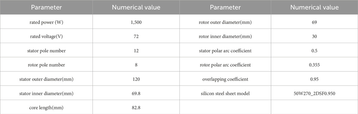
Table 1. Parameters of motor structure.
3.1 Static finite element analysis
The prototype model’s static finite element analysis uses ANSYS software. Considering the A-phase winding as an example, to analyze the torque generation capacity, the step is set as 0.5, the angle value is set from 0 to 45, and the Maxwell software calculates the torque and inductance values under the fixed phase current. The characteristic profiles of the inductor-rotor position and torque-inductor derivative are plotted using Matlab, as illustrated in Figures 1A,B.
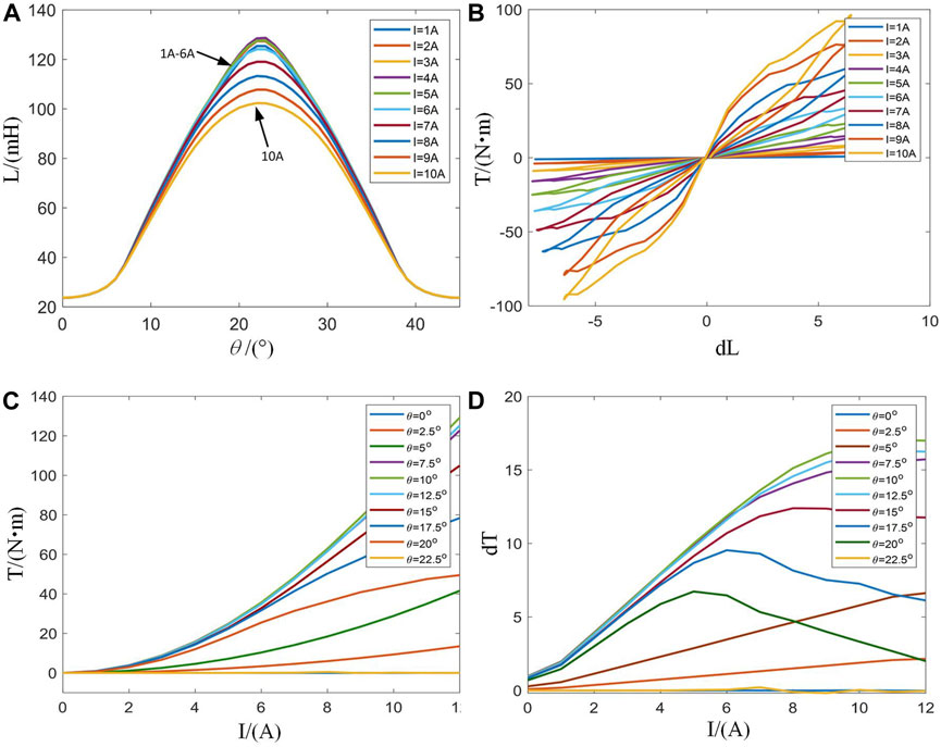
Figure 1. SRM static characteristic 2-D profiles. (A): Characteristic profiles of inductance versus rotor position. (B): Characteristic profiles of inductance derivative versus torque. (C): Characteristic profiles of current versus torque. (D): Characteristic profiles of current versus torque derivative.
Under the linear model, the magnetic saturation characteristic is ignored, and the phase current is fixed. Thus, the inductance derivative is linearly related to the torque. In order to analyze the influence of the inductance value on torque in practical applications, the step of the phase current is set to 1A. Figures 1A,B highlight that the coincidence degree of the inductance curves is high when the phase current is 1 6A. When the current exceeds 6 A, the motor is operated at the magnetic circuit saturation state, and the inductance value in the central area gradually decreases, showing a concave state. When the center lines of the stator’s and rotor’s salient poles are completely aligned, the motor enters a saturation state of the magnetic circuit. Then, the saturation effect increases as the phase current increases, the inductance value decreases, and the torque generation ability becomes weaker. When the front edge of the salient poles of the stator and rotor approach, the sensitivity of inductance increases, and the torque generation strengthens. Therefore, when the phase current is constant, the torque gradually increases as the inductance derivative increases and the relation between the inductance derivative and torque tends to be linear.
In order to analyze the influence of phase current on the torque generation capacity, the phase A winding is given a phase current 12A with a step of 1A, and the torque value varying with the phase current at a fixed angle is acquired. The torque-current and torque derivative-current characteristics profiles are plotted in Matlab, as depicted in Figures 1C,D.
In order to analyze the influence of phase current on torque in practical application, the step is set to 2.5, and the angle value of 0 22.5 is selected. When the angle is 0–7.5, the trailing edge of the stator pole is gradually approaching the leading edge of the rotor pole. When the angle is 7.5–22.5, the salient poles of the stator and rotor gradually coincide. Figures 1C,D highlight that the A-phase winding of the motor is conducting when the rotor position is 0–15, and the torque gradually increases as the current increases. At this time, the torque generation ability is strong. When the rotor position is 15–22.5, the A-phase winding of the motor is operated at the turn-off freewheeling state, the torque derivative-current value decreases obviously as the phase current exceeds 6A, and the torque generation ability weakens. Therefore, when the angle is fixed, the torque value gradually increases with the increase of phase current, and the relationship between current and torque tends to be square.
The torque profile is obtained by a two-dimensional static field analysis, as illustrated in Figure 2. By analyzing the influence of the current and inductance on the torque generation capacity, it is demonstrated that the torque generation capacity is stronger at points A and B.
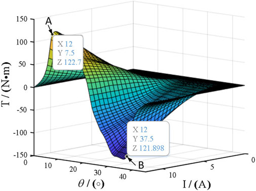
Figure 2. Value of torque with the change of parameters θ and current.
4 Torque share function control strategy
The SRM control block diagram of direct instantaneous torque control based on a torque closed loop is shown in Figure 3, which mainly includes the torque calculation unit, hysteresis control unit, power converter, SRM, position detector, and current sensor. As shown in Figure 3, the total reference torque Tref is divided into reference torques Tk_ref of each phase at different positions according to the torque share function. The look-up table module calculates the instantaneous output torque. The error between the reference torque and the instantaneous output torque is converted into the driving signal of the power converter by torque hysteresis control, and the control scheme is based on the torque share function.
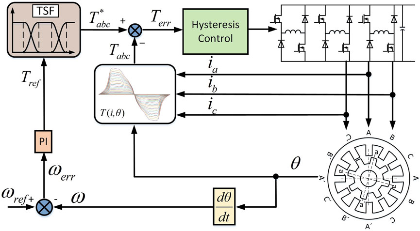
Figure 3. SRM control block diagram of DITC method.
4.1 Torque share module
To realize the control goal of the TSF method based on constant synthetic instantaneous torque, the following equation must be satisfied:
where Tk(θ) is the instantaneous torque of the kth phase winding, Tref is the synthesized instantaneous reference torque, fk(θ) is the torque share function of the kth phase winding, and m is the number of phases of SRM.
The torque share function directly affects the torque ripple and the reference peak current of each phase. Hence, the TSF function can effectively improve the steady-state performance of SRM. The common TSF functions include linear, cosine, cubic, and exponential. This paper analyzes the linear and cosine types, with their profiles and current diagrams depicted in Figure 4.
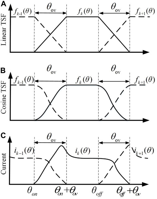
Figure 4. Profiles and current diagrams of linear and cosine TSF functions. (A): Profiles of linear TSF. (B): Profiles of cosine TSF. (C): Diagram of phase current and rotor position.
In a single rotor angular period, the reference torque of the kth phase can be expressed as:
where Tref is the total reference torque, frise is the slope of the rising phase of the input phase, and ffall is the slope of the falling phase of the output phase. θon, θoff, and θov represent the turn-on, turn-off, and overlapping angles, respectively, and τr is the rotor angle period. The relationship between frise and ffall is defined as:
θov should satisfy the following relational equation:
4.2 Partition torque correction control strategy
Generally, the tracking ability of the current is constrained by the power converter, and the traditional torque share function ignores the influence of current tracking characteristics. Therefore, the output torque of each phase cannot track the reference torque, resulting in a large torque ripple. This paper considers this limitation in the proposed torque distribution curve design. Figure 5A illustrates the schematic diagram of the TSF control strategy based on cosine, where the solid line presents the reference torque distributed by the TSF function, and the dotted line is the actual torque generated in the motor running process. The diagram reveals that the torque at the position with a small inductance cannot track the given torque in time, resulting in a large torque error. Aiming to solve the torque ripple problem, this paper proposes a method based on the partition correction of the torque share function. According to Figure 5B, the commutation period is divided into three sub-intervals (intervals I, II, and III) with θc1and θc2 denoting the midpoints. The torque generation capacity of each phase at a different rotor position is analyzed, and the phase with a strong torque generation capacity is selected as the torque compensation phase. The performance of the torque share function is optimized according to the real-time torque tracking error, and the control ability of the actual current is improved. Thus, the optimization goal of torque ripple suppression is achieved.
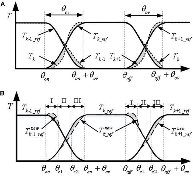
Figure 5. Schematic diagram of conventional and proposed TSF control strategy. (A): Cosine TSF control strategy. (B): Correction TSF strategy.
The torque characteristic at different rotor positions is presented in Figure 6, and the difference in torque generation capacity between the adjacent phases during commutation is presented in Figure 7. By analyzing the rate of change for the torque at the commutation, the torque share function is constructed by partition optimization for the torque ripple minimization.
(1) Interval I: At the initial stage of commutation, the torque generation capacity of the K phase is lower than the K-1 phase. The torque of the K-1 phase is used as compensation instead of the K phase. For correcting TSF, the control block diagram of interval I is presented in Figure 8A, suggesting that the torque generation capacity of the k-1 phase is greater than that of the K phase in interval I. At this time, the K phase is at the stage of establishing an excitation current. Thus, the current value is small, and the change rate of winding inductance is low. Therefore, the actual torque generated cannot track the reference torque. At this time, the torque generation capacity of the k-1 phase is strong, and the k-1 phase can compensate for the torque error generated by the k phase.
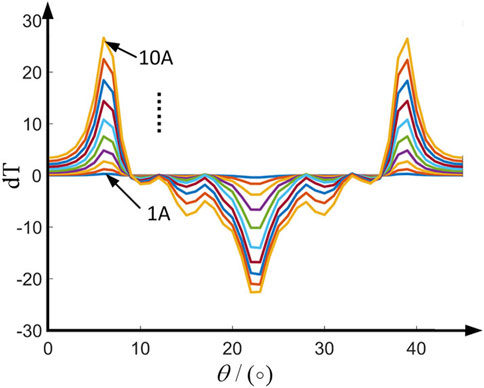
Figure 6. Simulation profiles of the torque characteristic at different rotor position.
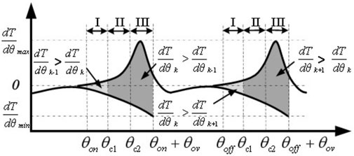
Figure 7. Diagram of torque generation capacity of different phases during commutation period.
The torque error of the K phase equation is
In the overlapping area, the total electromagnetic torque equals the sum of the electromagnetic torques of the input and output phases. The updated total reference torque can be expressed as:
The relationship between frise and ffall is defined as
(2) Interval II: In the middle of commutation, the torque generation capacity of the k-1 phase is similar to that of the K phase. The K phase is in the current conduction interval, with strong control ability. The K phase compensates for the torque error caused by commutation.
The control block diagram of interval II correction TSF is depicted in Figure 8B, highlighting that the torque-generating capacity of the k-1 phase is similar to that of the K phase. At this time, the k-1 phase is at the turn-off freewheeling state, the current gradually decreases, the torque is in a state with a fixed profile decline, and the current control ability is weak. The k-phase current in this interval is rising, and the controllability is strong. Therefore, the k-phase is selected for torque compensation in interval II.
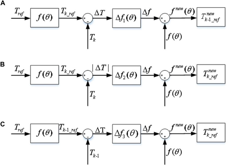
Figure 8. Control block diagram of correction TSF of three sub-intervals. (A): Control block diagram of correction TSF of interval I. (B): Control block diagram of correction TSF of interval II. (C): Control block diagram of correction TSF of interval III.
The torque error generated in this interval is:
The compensation function ΔfII can be expressed as:
(3) Interval III: In the later stage of commutation, the torque generation capability of the k-1 phase is lower than that of the k-phase. The block diagram of the interval III correction TSF control is illustrated in Figure 8C, revealing that the torque-generating capability of the k-phase is greater than that of the k-1 phase. At this time, the rate of change of the k-1 phase winding inductance is small. Thus, the phase torque is large, which causes the actual torque to exceed the reference torque, resulting in torque ripples. Additionally, the torque generation capability of the k-phase is relatively strong, so the k-phase compensates for the torque error generated by k-1.
The torque error of the k-1 phase can be expressed as:
The modified torque share function expression with adding the compensation function in sections is presented below:
4.3 Evaluation criteria of torque share function control strategy
In order to ensure the stable operation of the motor in speed and torque output, this paper comprehensively considers the torque share function control strategy indicators.
The torque ripple of the motor Tr is defined as:
where Tmax is the maximum torque, Tmin is the minimum torque, and Tav is the average torque.
Copper loss is one of the important factors affecting the operating efficiency of the motor, which can be expressed by the RMS value Irms during the conduction period:
The copper loss of SRM is proportional to the square of the phase current, and the copper loss generated by the motor operation can be reduced by reducing the motor’s phase current.
The flux linkage change rate of the motor is expressed as:
where the voltage drop RkIk of the winding resistance is usually small compared to the dc-link voltage, and thus, the term RkIk can be ignored in qualitative analysis. The above formula highlights that the flux linkage change rate is only affected by the DC-link voltage, the current change rate, and rotational speed.
5 Simulation analysis
The effectiveness of the proposed control strategy is verified using a three-phase 12/8 switched reluctance motor, where the flux linkage and torque characteristics of the switched reluctance motor are obtained using the Maxwell software. Figure 9, Figure 10, and Figure 11 illustrate the results of the traditional linear TSF, cosine TSF, and improved cosine TSF in the simulation test. For this trial, the parameters are configured as follows: dc-link voltage 72 V, given rotating speed 500r/min, turn-on angle, and turn-off angle are 0° and 22.5°.
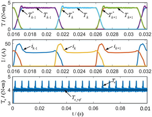
Figure 9. Simulation results of cosine TSF control strategy.

Figure 10. Simulation results of proposed TSF control strategy.
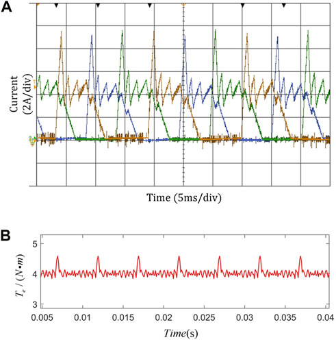
Figure 11. Experimental results of cosine TSF control strategy. (A): Current waveform. (B): Torque waveform.
According to the simulation results, the torque ripple of traditional linear TSF and cosine TSF is 25% and 23%, respectively. Compared with the traditional TSF method, the torque ripple is reduced when using the proposed TSF, and the tracking ability of the torque is improved. The torque ripple is reduced from 23% to 18.6%. The simulation shows the motor has stronger torque ripple suppression ability using the modified torque share function partition control strategy.
6 Experimental analysis
An experimental platform for SR motor control is set up to verify the feasibility of the proposed torque ripple suppression control strategy. The experimental platform employs an STM32F103C8T6 chip as the control core and a 12/8 three-phase switched reluctance motor as the research object. The power converter adopts a three-phase asymmetric half-bridge circuit, and its rated speed is 2000r/min.
The experiment considers fixed turn-on and turn-off angles, and the reference speed is 500r/min. The results of the traditional cosine TSF and the improved cosine TSF are compared, and the experimental results are shown in Figures 12A,B, and Figure 13. The results infer that the improved cosine TSF adopted in this paper can improve the torque ripple during commutation and that the control index is better in a wide speed range.
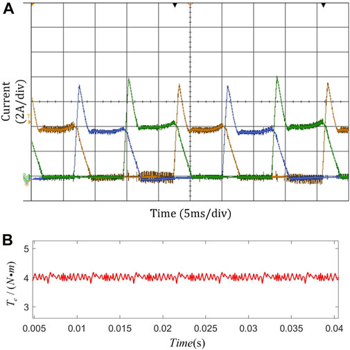
Figure 12. Experimental results of cosine TSF control strategy. (A): Current waveform. (B): Torque waveform.
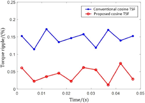
Figure 13. Torque Ripple Comparison of cosine TSF and correction TSF.
7 Conclusion
In order to reduce the torque ripple effectively, a torque ripple suppression control strategy of switched reluctance motor based on partitioned TSF is proposed in this paper. In this control strategy, the torque share function is modified partitionally by using the difference of two-phase torque generation capacity during commutation. This method fully considers the problem of torque generation ability, which reduces the dependence of power converter, and achieves low torque ripple index, it also can be widely applied to other switched reluctance motors with different topologies. The simulation and experimental results show that the proposed control strategy can significantly reduce the torque ripple during commutation in a wide speed range and improve the reliability of motor operation.
Data availability statement
The original contributions presented in the study are included in the article/Supplementary material, further inquiries can be directed to the corresponding author.
Author contributions
CH: Writing–original draft, Writing–review and editing, Conceptualization, Data curation, Formal Analysis, Funding acquisition, Investigation, Methodology, Project administration, Resources, Software, Supervision, Validation, Visualization. HY: Conceptualization, Data curation, Funding acquisition, Investigation, Methodology, Resources, Software, Validation, Visualization, Writing–original draft. PY: Conceptualization, Formal Analysis, Funding acquisition, Investigation, Project administration, Resources, Software, Supervision, Validation, Writing–original draft. TZ: Conceptualization, Data curation, Funding acquisition, Investigation, Methodology, Project administration, Resources, Supervision, Validation, Visualization, Writing–original draft.
Funding
The author(s) declare that no financial support was received for the research, authorship, and/or publication of this article.
Conflict of interest
Author YH is employed by BYD Company Ltd.
PY is employed by Ruili Group Rui’an Auto Parts Co. Ltd.
The remaining authors declare that the research was conducted in the absence of any commercial or financial relationships that could be construed as a potential conflict of interest.
Publisher’s note
All claims expressed in this article are solely those of the authors and do not necessarily represent those of their affiliated organizations, or those of the publisher, the editors and the reviewers. Any product that may be evaluated in this article, or claim that may be made by its manufacturer, is not guaranteed or endorsed by the publisher.
References
Cao, Y., Zhou, B., Chung, C., Wu, T., Zheng, L., and Shuai, Z. (2024). A coordinated emergency response scheme for electricity and watershed networks considering spatio-temporal heterogeneity and volatility of rainstorm disasters. IEEE Trans. Smart Grid 1, 1. doi:10.1109/TSG.2024.3362344
Chen, F., Jianhu, Y., Pan, W., and Zhao, Y. (2018). Torque ripple suppression of switched reluctance motor based on modified torque sharing function. Trans. China Electrotech. Soc. 33, 394–400. doi:10.19595/j.cnki.1000-6753.tces.180593
Cheng, H., Zhang, D., Liao, S., Shao, D., and Hu, Y. (2022). Integrated drive converter of sds-srm with isolation and nonisolation charging capabilities for electric vehicle. IEEE Trans. Industrial Electron. 69, 8679–8691. doi:10.1109/tie.2021.3116569
Dang, X., Shi, Y., and Peng, H. (2020). Torque–flux linkage recurrent neural network adaptive inversion control of torque for switched reluctance motor. IET Electr. Power Appl. 14, 1612–1623. doi:10.1049/iet-epa.2020.0105
Dowlatshahi, M., Nejad, S. M. S., and Ahn, J.-W. (2013). “Torque ripple minimization of switched reluctance motor using modified torque sharing function,” in 2013 21st Iranian conference on electrical engineering (ICEE) (IEEE), 1–6.
Kim, J.-H., and Kim, R.-Y. (2018). Sensorless direct torque control using the inductance inflection point for a switched reluctance motor. IEEE Trans. Industrial Electron. 65, 9336–9345. doi:10.1109/TIE.2018.2821632
Kuang, S., Zhang, X., Zhang, Z., and Jiang, H. (2019). Sensorless control of switched reluctance motor based on intersection angle compensation of phase inductance. Trans. China Electrotech. Soc. 34, 4909–4917. doi:10.19595/j.cnki.1000-6753.tces.181491
Li, C., Zhang, C., Liu, J., and Bian, D. (2021). A high-performance indirect torque control strategy for switched reluctance motor drives. Math. Problems Eng. 2021, 1–15. doi:10.1155/2021/6618539
Li, H., Bilgin, B., and Emadi, A. (2018). An improved torque sharing function for torque ripple reduction in switched reluctance machines. IEEE Trans. Power Electron. 34, 1635–1644. doi:10.1109/TPEL.2018.2835773
Liu, D., Zhao, Y., and Fan, Y. (2019). “Subsection pwm variable duty cycle control of switched reluctance motor based on torque sharing function,” in 2019 Chinese control conference (CCC) (IEEE), 3243–3247.
Ma, M., Yu, F., Yang, Q., Wang, R., and Zhang, X. (2018). Control strategy of minimizing torque ripples of the switched reluctance motor by injecting piecewise harmonic currents. Zhongguo Dianji Gongcheng Xuebao/Proceedings Chin. Soc. Electr. Eng. 38, 285–291. doi:10.13334/j.0258-8013.pcsee.170276
Marcsa, D., and Kuczmann, M. (2017). Design and control for torque ripple reduction of a 3-phase switched reluctance motor. Comput. Math. Appl. 74, 89–95. doi:10.1016/j.camwa.2017.01.001
Qing, L., Wang, H., Ge, X., and Jiang, H. (2020). A high efficiency torque ripple suppression method for switched reluctance motor. Trans. China Electrotech. Soc. 35, 1912–1920. doi:10.19595/j.cnki.1000-6753.tces.190035
Sun, Q., Wu, J., and Gan, C. (2020). Optimized direct instantaneous torque control for srms with efficiency improvement. IEEE Trans. Industrial Electron. 68, 2072–2082. doi:10.1109/TIE.2020.2975481
Sun, Q., Wu, J., Gan, C., Hu, Y., and Si, J. (2016). Octsf for torque ripple minimisation in srms. IET Power Electron. 9, 2741–2750. doi:10.1049/iet-pel.2016.0270
Sun, X., Diao, K., Lei, G., Guo, Y., and Zhu, J. (2019). Direct torque control based on a fast modeling method for a segmented-rotor switched reluctance motor in hev application. IEEE J. Emerg. Sel. Top. Power Electron. 9, 232–241. doi:10.1109/JESTPE.2019.2950085
Sun, X., Shen, Y., Wang, S., Lei, G., Yang, Z., and Han, S. (2018). Core losses analysis of a novel 16/10 segmented rotor switched reluctance bsg motor for hevs using nonlinear lumped parameter equivalent circuit model. IEEE/ASME Trans. Mechatronics 23, 747–757. doi:10.1109/TMECH.2018.2803148
Xia, Z., Bilgin, B., Nalakath, S., and Emadi, A. (2020). A new torque sharing function method for switched reluctance machines with lower current tracking error. IEEE Trans. Industrial Electron. 68, 10612–10622. doi:10.1109/TIE.2020.3037987
Xi-Lian, W., Zhen-Liang, X. U., and Cui, W. (2015). Torque ripple and copper losses minimization control study of switched reluctance motor. Electr. Mach. Control 19, 7. doi:10.15938/j.emc.2015.07.008
Keywords: switched reluctance motor, torque sharing function, torque ripple minimization, torque control, optimization
Citation: Hui C, Yanjie H, Yinbin P and Tao Z (2024) A method for reducing torque ripple of switched reluctance motor based on partitioned TSF. Front. Energy Res. 12:1381950. doi: 10.3389/fenrg.2024.1381950
Received: 04 February 2024; Accepted: 28 March 2024;
Published: 23 May 2024.
Edited by:
Liansong Xiong, Xi’an Jiaotong University, ChinaReviewed by:
Zhifeng Qiao, Tianjin University of Technology, ChinaFei Jiang, Changsha University of Science and Technology, China
Kai Zhang, Zhongyuan University of Technology, China
Copyright © 2024 Cai, Han, Pan and Tao. This is an open-access article distributed under the terms of the Creative Commons Attribution License (CC BY). The use, distribution or reproduction in other forums is permitted, provided the original author(s) and the copyright owner(s) are credited and that the original publication in this journal is cited, in accordance with accepted academic practice. No use, distribution or reproduction is permitted which does not comply with these terms.
*Correspondence: Cai Hui, NDE2ODQ2NzQ5QHFxLmNvbQ==