 Hengjie Luan
 Mingkang Liu1
 Qinglin Shan
 Yujing Jiang
 Bo Li
Bo Li
94% of researchers rate our articles as excellent or good
Learn more about the work of our research integrity team to safeguard the quality of each article we publish.
Find out more
ORIGINAL RESEARCH article
Front. Energy Res., 07 March 2024
Sec. Advanced Clean Fuel Technologies
Volume 12 - 2024 | https://doi.org/10.3389/fenrg.2024.1377400
This article is part of the Research TopicAdvances in Geomechanics Research and Application for Deep Unconventional ReservoirsView all 35 articles
Natural fractures and cavities are the primary spaces for oil and gas accumulation in fracture-cavity carbonate reservoirs. Establishing the connection between these spaces and the wellbore through hydraulic fracturing treatment is important for oil and gas extraction from such reservoirs. Due to the discontinuity and heterogeneity of the existing natural fracture-cavity system, anticipating the viability of hydraulic fracturing treatment is troublesome. A new method to simulate the hydraulic fracturing propagation in fracture-cavity reservoirs is proposed based on the continuous damage theory. The method considers the random spatial distribution of fractures and cavities and can simulate the arbitrary expansion of hydraulic fractures in the three-dimensional direction. Based on this method, the influence of different geological and engineering factors on the propagation patterns of hydraulic fractures in the fracture-cavity reservoirs is investigated. It is found that the increase of reservoir burial depth significantly limits the propagation ranges of hydraulic fractures. The propagation modes of hydraulic fractures encountering natural fractures change with increasing burial depth, undergoing a transition from “penetrate and deflect” to ”defect” and then to ”penetrate”. The reduction of horizontal stress difference increases the complexity of hydraulic fractures, but it is not conducive for hydraulic fractures to connect more natural fractures and cavities. The increase in fracturing pump rate is significantly beneficial for hydraulic fractures to connect more natural fractures and cavities. The viscosity of fracturing fluid has a significant impact on the morphology of hydraulic fracture propagation, which undergoes a transition from simple to complex, and then to simple with the change of the fracturing fluid viscosity from low to high. either too high or too low viscosity of the fracturing fluid is not conducive to the connection of more natural fractures and cavities by hydraulic fractures. The obtained conclusions can provide a reference for the design of hydraulic fracturing treatment for fracture-cavity carbonate reservoirs.
In recent years, It has been becoming increasingly important to explore and develop the fracture-cavity reservoirs, especially in deep basins worldwide (Tian et al., 2019; Wang et al., 2019). Fracture-cavity carbonate reservoirs with extreme internal heterogeneity and burial depth of more than 5,000 m are widely distributed in the Tahe oilfield in Xinjiang, China (Zhang et al., 2004; Mousavi et al., 2013; Xu et al., 2016; Jiao, 2019; Ren et al., 2020; Huang et al., 2022; Zhang et al., 2022; Huang et al., 2023a). In Tarim Basin, oil and gas reserves of the discovered fracture-cavity reservoirs could reach to 1 billion tons (Xiao et al., 2016; Zheng et al., 2019). Therefore, the efficient development of oil and gas in fracture-cavity reservoirs is of great significance. A typical carbonate fracture-cavity stratum is shown in Figure 1 (Qiao et al., 2022). As we can see, such stratum is randomly distributed with natural fractures and cavities of varying sizes. Compared with conventional reservoirs, fracture-cavity carbonate reservoirs have a dense matrix with pores compacted under high pressure, which basically do not have hydraulic connectivity and mobility (Kang et al., 2004; Chalikakis et al., 2011; Lv et al., 2011; Ji et al., 2015; Huang et al., 2018; Zhang et al., 2019; Tan et al., 2021; Zheng et al., 2022; Luo et al., 2022). Hydraulic fracturing treatment to enhance the connection between the wellbore and oil and gas enriched fracture-cavity system is one of the commonly used techniques to increase oil and gas production from fracture-cavity carbonate reservoirs (Rahm, 2011; Huang et al., 2020; Liu et al., 2020). Given the deep burial and the non-uniformly distributed natural fractures and cavities, there are still many uncertainties and room for improvement in understanding how the extreme heterogeneity influence the hydraulic fracture propagation and how to optimize the fracture-cavity reservoir stimulation treatment.
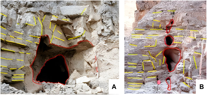
FIGURE 1. Typical carbonate fracture-cavity strata outcrops (Qiao et al., 2022). (A) Natural fractures and a single large cavity; (B) Natural fractures and a group of cavities.
In past studies, a lot of research on the general behaviour of hydraulic fractures in heterogeneous reservoirs containing natural fractures has been carried out physically and numerically. Physical simulations can provide intuitive experimental results and are widely used to simulate the expansion of hydraulic fractures. Zhou experimentally investigated the influence of random natural fracture systems on the geometry and propagation behavior of hydraulic fractures, and found both random natural fractures and in-situ stress differences govern the hydraulic fracture geometry and propagation behavior (Zhou et al., 2010). Liu used true triaxial volumetric fracturing experiments to investigate the factors affecting the hydraulic fracture propagation, and found that the presence of random natural fractures around the wellbore, the size of the random natural fractures, the bulk density of the specimens, and the horizontal differential stresses all play a role in the process (Liu et al., 2018). Hou conducted a series of large-scale true triaxial experiments with acoustic emission monitoring, and found that low-viscosity fluid can activate discontinuities to form a complex fracture network, whereas a high-viscosity fluid is likely to produce large fractures under a high contrast in the horizontal stresses (Hou et al., 2018). Guo carried out physical simulations of triaxial hydraulic fracturing in tight sandstone and investigated the influences of natural fracture development degree, in-situ stress conditions, and fracture treatment parameters on fracture propagation, and found that natural fracture played an important factor on hydraulic fracture morphology in tight sandstone reservoirs (Guo et al., 2021). Tan carried out experiment tests on several groups of combination samples comprised of artificial rocks to study the effects of in-situ stress, injection rate, natural fracture and well type on fracture growth in coal measure strata, and found the behavior of the hydraulic fracture also varied significantly between vertical and horizontal wells (Tan et al., 2023). Numerical simulation methods can overcome the limitations of physical test specimen size and are widely used in the study of hydraulic fracture propagation. Chuprakov conducted a parameter sensitivity analysis of the fracturing interaction process using numerical simulation, and the numerical results showed the fracture interaction angle, in-situ stress parameters, the injection rate and viscosity of the fracturing fluid are important parameters controlling whether or not a hydraulic fracture can penetrate a natural fracture (Chuprakov et al., 2013). Zhang et al. (2017) developed a hybrid discrete-continuous numerical scheme to study the behavior of hydraulic fractures under the influence of natural fractures, and the simulation results showed different propagating paths under various stress ratios and roughness of the natural fracture surface and that the complexity of fracturing increases as the number and scale of natural fractures increase. Shan established a fracturing model based on the continuous damage theory and investigated the influences of three factors, namely, geostress difference, fracture fluid viscosity, and pump rate, on the hydraulic fracturing patterns in laminated Shan et al. (2018). Wang (2019) presented a global cohesive zone model to study hydraulic propagation in naturally fractured reservoirs. Qiao et al. (2022) also showed that natural fractures have a great influence on the propagation of hydraulic fractures through the numerical simulation study of the hydraulic fracture propagation behavior of natural fractures under different influencing factors using the TOUGH-AiFrac simulator. There are still many other studies. Huang performed simulation to study the interaction between hydraulic fractures and gravels in glutenite formation based on 2D particle discrete element method, and results showed that the non-uniformly distributed stress field caused by the existence of glutenite maily affects the fracture propagating path (Huang et al., 2023b). Although the reservoir types studied are different and the methods used are also varied, these studies have reached similar conclusions regarding the expansion behavior of hydraulic fractures in fractured reservoirs (Song et al., 2017; Tan et al., 2017; Huang et al., 2019; Song et al., 2020; Tan et al., 2020; He et al., 2023; Liu et al., 2023; Wu et al., 2023). They all agreed the significant influence of reservoir heterogeneity and geostress states on the propagation path of hydraulic fractures, as well as the control effect of fracturing fluid flow rate and viscosity on the morphology of hydraulic fracture propagation.
Using similar methods as above, a few researches have been carried out on the propagation behaviour of hydraulic fractures in fracture-cavity carbonate reservoirs. Liu conducted a series of physical simulations of hydraulic fracturing under true triaxial stress states, to examine the influence of the cavity on the propagation of hydraulic fractures, and found that hydraulic fracturing turned to deflect by expanding around a cavity at low levels of stress difference (Liu et al., 2019). Cheng used the extended finite element method to simulate the interaction of hydraulic fracture with natural cavities and analyzed the influences of cavity location and horizontal stress difference on the interaction patterns of fractures and cavities (Cheng et al., 2019). Liu examined the connecting mechanisms between hydraulic fractures and cavities through experiments and numerical simulations, and found the importance of the connection of natural fractures by hydraulic fractures to enhance the oil/gas production from fracture-cavity reservoirs (Liu et al., 2020). Kao developed a solid-seepage-freeflow coupled fracturing model based on the discontinuous discrete fracture method to simulate the complex interaction behavior of fractures and cavities, and found the stress concentration around cavities is the main factor determining fracture propagation path (Kao et al., 2022). Zhu establishes a new coupled thermal-hydraulic-mechanical-chemical model to simulated acid fracturing in fracture-cavity reservoirs by treating natural fractures hierarchically, meanwhile different coupling methods were used for fractures of different scales (Zhu et al., 2023). In addition, Wang (Wang et al., 2018) and Luo (Luo et al., 2020) analyzed the intersection behavior of a single artificial fracture with a single cavity by numerical simulations, and the results showed that the presence of the cavities will disturb the fracture propagation path and make the fracture deflect.
Table 1 shows the summaries of research methods in published literature and future researching scope. At the present stage, most physical simulation experimental researches on the interaction between hydraulic fractures and cavities considering the effect of preset individual or limited numbers of cavities. What’s more, the physical experiments on samples with relatively small size makes it difficult to quantitatively analyze the interaction law between hydraulic fractures and cavities. Also, most of the current numerical methods simulated interactions between hydraulic fractures and natural fracture-cavity systems on a two-dimension space, ignoring the effect of the objective conditions of the random spatial distribution of cavities in three-dimensional space, which is a significant gap with reality. Therefor, there is an urgent need to propose a new hydraulic fracture propagation model suitable for fracture-cavity reservoirs to meet the requirements of deep reservoir fracturing simulations.
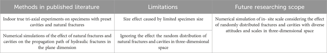
TABLE 1. Summaries of research methods in published literature and future researching scope.
Given the above analyses, a new method based on the continuous damage theory for hydraulic fracture simulation of fracture-cavity carbonate reservoirs is developed, which can consider the effect of randomly distributed fractures and cavities in three-dimensional space. Based on this model, the influences of different geologic and engineering factors on the propagation pattern of hydraulic fracture of the fracture-cavity reservoirs were investigated. The results of the study can provide guidance for the design of the fracture-cavity reservoir stimulation treatment.
The continuous damage method has been proven to effectively simulate the dynamic expansion and complex morphology of hydraulic fractures, in which, the propagation direction of damage fractures are spontaneously determined by the material constitutive behavior (Busetti et al., 2012a; Busetti et al., 2012b). Previous research has proved that this method has advantages in simulating hydraulic fracture propagation in computational regions with geometric complexity and material heterogeneity (Shan et al., 2018; Shan et al., 2018). Therefore, in this paper we decides to use the continuous damage method to simulate hydraulic fracture propagation under the influence of heterogeneity in fracture-cavity reservoirs.
Hydraulic fracturing is a complex seepage-damage-stress coupling problem. To accurately simulate hydraulic fracture propagation, it is necessary to take into account the pore seepage of the rock, the deformation of the fractures, the fluid flow in the fractures, and the effect of natural fractures. The numerical method based on continuous damage theory is an important means to simulate hydraulic fracture propagation. The method uses the internal variable, damage factor, to describe the damage degree of an element, and associates the stiffness, strength, and seepage parameters of the element with the damage factor, so that the hydraulic fracture propagation process can be equated to damage evolution of the model. The main modeling theories are briefly introduced in the following.
The permeability of the carbonate reservoir matrix is extremely low. However, to simulate the propagation of hydraulic fracture by using the continuous seepage-damage-stress coupling theory, the matrix still needs to be assumed to be a porous elastic medium. The deformation of the matrix by external loads and the process of pore fluid seepage satisfy the differential equations of stress equilibrium and the equation of conservation of seepage mass (Detoumay and Cheng, 1993; Xu et al., 2010; Shan et al., 2018), which are denoted as:
Where
The process of hydraulic fracturing treatment involves continuously injecting fluid into the reservoir and holding up high pressure. When the pressure exceeds the strength limit of the rock, hydraulic fractures occur. Thus, a rock strength model for predicting hydraulic fracture initiation is needed, and here a hyperbolic Drucker-Prager plasticity model (Drucker and prager. 1952) is used as a criterion for fracture initiation, which can take into account the prediction of tensile and compressive shear failure of the rock (Hibbitt et al., 2016):
Where
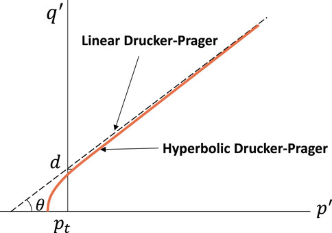
FIGURE 2. Comparison of the linear form and hyperbolic form of Drucker-Prager criterion in the
When the rock element reaches its strength limit under external loads, damage occurs. And macroscopic fracture occurs when the damage develops to a certain degree. The stiffness and strength of the rock at this stage can be expressed as a function of damage factor (Tang et al., 2002), For example, the stiffness and strength change with damage as:
Where
The brittle behavior of rock is characterized by damage-displacement response, which could be used to define the energy required to open an element area of fracture (Hillerborg et al., 1976), as shown in Figure 3. When the rock element is deformed in an elastic phase, the damage factor is zero. It is generally accepted that damage occurs with plastic deformation and changes dramatically with increasing plastic deformation. The relationship between damage factor and plastic deformation can be fitted based on rock mechanical experimental parameters (Shan et al., 2018)
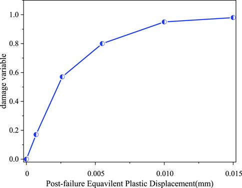
FIGURE 3. Relationship between
Where
When the rock is damaged under external load, the permeability of the rock is inevitably affected due to the formation of microfractures. Here, the permeability of damaged rocks is described in three stages based on the results of previous research (Zhou et al., 2010; Shan et al., 2018). For undamaged rock element, the permeability is a function of the mean stress; when the rock element is damaged but no macroscopic fractures occur, the permeability is considered to be mainly influenced by the mean stress and the degree of damage; after the formation of a macroscopic fractures, the permeability is defined using the cube law, which is expressed as:
where
The above are the main theoretical equations to realize the simulation of hydraulic fracture propagation. There is an obvious coupling relationship between seepage, stress, and damage. During the hydraulic fracturing process, as the fracturing fluid is injected, the rock near the wellbore is damaged under hydraulic pressure. With the damaged area increased, the rock permeability is also increased, leading more fracturing fluid infiltration into the rock to further reduce the effectively stress, which promotes the formation of macroscopic fracture under the tensile stress. This process repeatedly occurs at the tip of hydraulic fractures, which promotes the forward propagation of the hydraulic fracture. The specific coupling process can be seen in Figure 6. Due to the large number of physical quantities involved and the nonlinear deformation characteristics, the finite element method is used here to solve the above equations.
To improve simulation efficiency, commercial software, ABAQUS, is used for building the model geometry and solving formulas, and we develop a user subroutine code to associate the rock element parameters with the damage variable to achieve the coupling of stress, seepage and damage (Hibbitt et al., 2016). The model geometric is discretized by linear tetrahedral elements. The Formula (1–6) are solved by principle of minimum potential energy using implicit method. Before applying this simulation method to fracture-cavity reservoirs, the effectiveness of the simulation method should be verified first.
Due to the fact that the ability of continuous damage methods in simulating the free propagation of hydraulic fractures in three-dimensional space and interaction between natural fractures and hydraulic fractures has been proved (Shan et al., 2018; Shan et al., 2018), here we only demonstrate the ability of the continuous damage method to simulate the influence of cavities on the direction of hydraulic fracture propagation. We will refer to existing physical simulation results (Liu et al., 2019) and compare them with the numerical simulation results calculated by our model to verify the effectiveness of the numerical method proposed in this study. In Liu’s study, The experiments demonstrated the influence of cavities on the propagation path of hydraulic fractures under different conditions of geostress differences. Referring to his experimental process, we establish a geometric model of the same scale and assign the same material properties and boundary conditions. As shown in Figure 4 are the model geometry and the loading direction. It can been seen the cavity is pre-set on the potential expansion path of hydraulic fractures. Two loading schemes are designed to investigate the influence of geostress differences on fracture propagation paths refereeing Liu’s study, where in Case 1, the
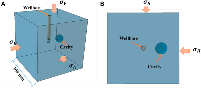
FIGURE 4. Model geometry of experimental scale and the loading direction, (A) 3D view; (B) vertical view.
Figures 5–7 show the numerical results and their comparison with experimental results. The green area in numerical simulations is the rock damage area, and its dynamic evolution can be equivalent to the path of hydraulic fractures. The numerical simulations obtained results consistent with the physical simulations. That is under high horizontal stress difference condition, it is easy for hydraulic fractures to connect the cavity that located in the direction of maximum horizontal stress (Figures 5, 7A). However, when the horizontal stress difference is low, the hydraulic fractures are prone to bypass the cavity (Figure 6; Figure 7B) due to the stress concentration around the cavity, as expressed in Cheng and Kao’s work (Cheng et al., 2019; Kao et al., 2022). It can be seen the numerical simulation method perfectly reproduces the experimental results. Therefore, the new simulation method proposed is effective and can be used for simulating hydraulic fracture propagation in fracture-cavity reservoirs.
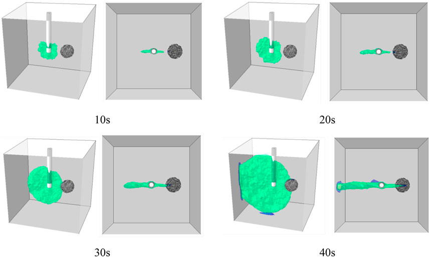
FIGURE 5. Hydraulic fracture propagation process of Case 1, displayed in 3D view and vertical view.

FIGURE 6. Hydraulic fracture propagation process of Case 2, displayed in 3D view and vertical view.
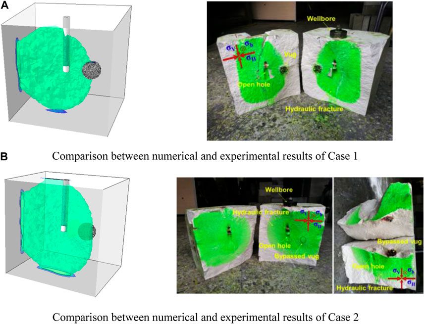
FIGURE 7. Comparison between numerical and experimental results (Liu et al., 2019). (A) Comparison between numerical and experimental results of Case 1. (B) Comparison between numerical and experimental results of Case 2.
According to the typical heterogeneity characteristics of fracture-cavity carbonate reservoirs, it is not suitable to use plane assumption, therefore, a three-dimensional model is established for the simulation. The scale of the model is 100 m × 100 m × 60 m (Figure 8A), and a cluster of perforations is set up in the center of the model with perforation phase of 60° and perforation number of 6 (Figure 8B). Referring to on-site seismic logging data and literature parameters (Kao et al., 2022), as shown in Table 2, randomly distributed natural fractures and cavities are generated in pre-processing stage (Figures 8C, D), assuming the natural fractures are elliptical and the cavities are spherical. To ensure the accuracy of the simulation results and computational efficiency, the geometric model is meshed using a tetrahedral mesh, and the grid is encrypted at the locations of the wellbore, perforation holes, natural fractures, and cavities (Figure 9).
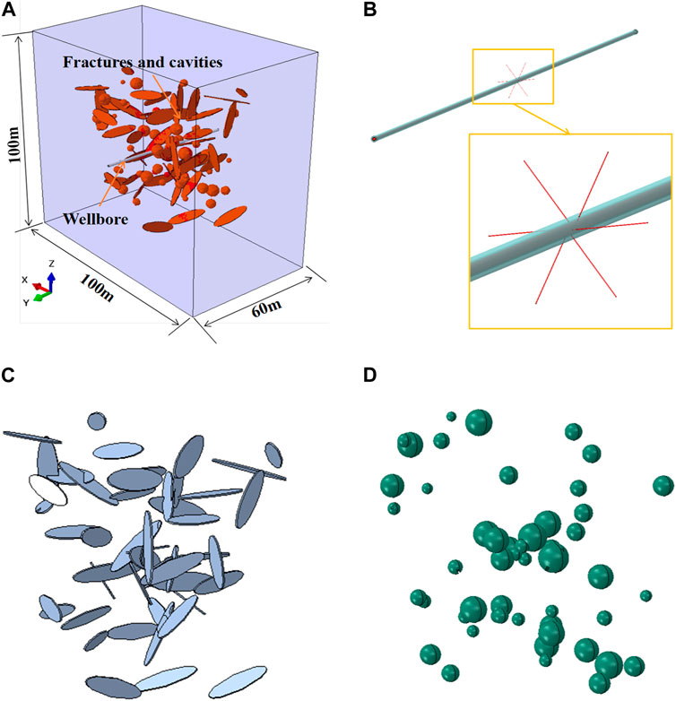
FIGURE 8. (A) Whole geometric model; (B) Set of wellbore and perforations; (C) Set of natural fractures; (D) Set of natural cavities.
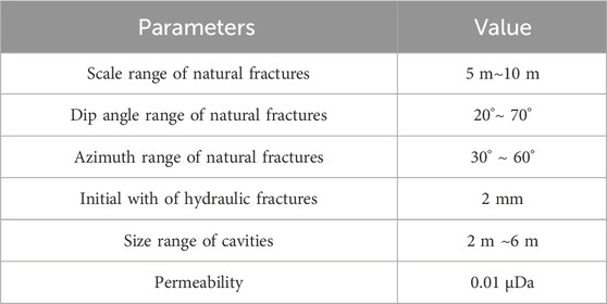
TABLE 2. Geometric parameters of natural fractures and cavities.
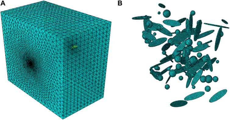
FIGURE 9. (A) Whole model meshed by tetrahedron grids; (B) Mesh encryption at key locations.
Table 3 shows the reservoir rock material parameters, including the parameters related to the damage-permeability evolution of the reservoir rock. For material parameters of natural fractures and cavities, the nonzero initial damage variables are set for the natural fractures and cavities so that the natural fractures and cavities have lower initial strength and stiffness and higher initial permeability compared with the rock matrix. Here the initial damage variable for the natural fracture elements is set to be 0.9 and the initial damage variable value for the natural cavity elements is set to be 1 (i.e., complete damage with very low strength and very high permeability).
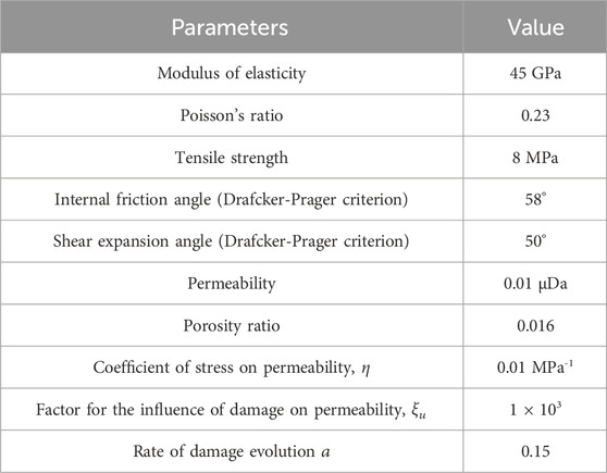
TABLE 3. Model reservoir rock material parameters.
It is assumed that the wellbore is along the direction of the minimum horizontal stress, and the reservoir is in the state of positive fault geostress. The formation pressure gradient is set to 1.1 MPa/100 m, the vertical geostress gradient is taken as 2.2 MPa/100 m, and the maximum horizontal geostress gradient and the minimum horizontal geostress gradient are taken as 2.07 MPa/100 m and 1.8 MPa/100 m, respectively. The constant pore pressure boundary condition is applied in our model considering the model geometry is large enough to avoid the boundary effect on hydraulic fracture propagation. The viscosity and pump rate of the fracturing fluid is set concerning the range of values commonly used in field design.
The above-mentioned is the basic theory and key parameters of the model, and the overall computational flow is shown in Figure 10. The geometric model is first established containing different sets, such as the rock body matrix, natural fractures, and cavities. Then different model sets are respectively assigned with different material parameters and initial damage variables. Then the whole model is meshed and the boundary conditions are applied before calculation. During the calculation stage, the elements’ damage state is updated in each analysis step to determine the elements’ mechanics and permeability parameters, which are used to obtain the new stress and deformation field of the model. As the coupling calculation continues, the dynamic propagation process of hydraulic fracture characterized by damage can be simulated.
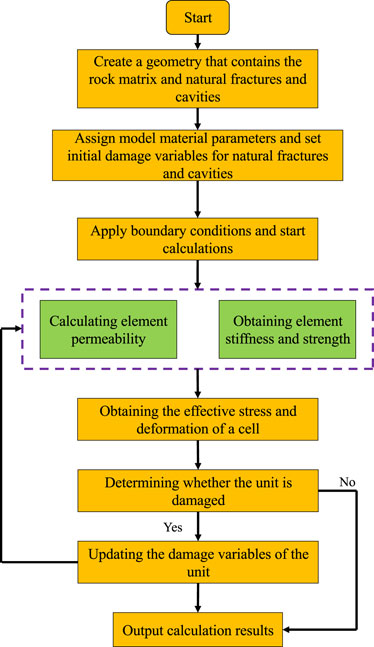
FIGURE 10. Numerical calculation flow.
Figure 11 shows the hydraulic fracture propagation process of a simulation case with reservoir burial depth of 3,500 m. Due to the fact that this study only considers the case of one perforation cluster, the selected pump rate value is relatively small. Here, fracturing fluid pump rate of 2 m3/min and viscosity of 3 mPa·s. It is worth noting that, although the legend in Figure 11 shows a damage range of 0∼1, the hydraulic fracturing is only marked in green. That is because we selectively expose one damage isosurface, which is damage of 0.5 marked in green, to display the three-dimensional morphology of hydraulic fractures more clearly. As we can see in Figure 11, at an injection time of 100 s, the hydraulic fracture starts from the injection hole location. When the injection time is 300 s, the hydraulic fractures initiated from each perforation converge to form a single fracture surface. With the continuous injection of fracturing fluid, the hydraulic fracture continued to propagate, connecting natural fractures and cavities.
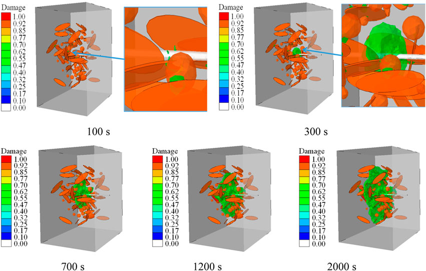
FIGURE 11. Propagation process of hydraulic fracture under the condition of reservoir.
Given that fracture-cavity carbonate reservoirs to be developed are becoming deeper in burial depth, the influence of geological factors on hydraulic fracture propagation is becoming more and more significant. Based on the above modeling theory, this paper seeks to explore the influence and control mechanism of geological and engineering factors on the hydraulic fracture propagation of fracture-cavity carbonate reservoirs through factor analysis as follows:
Keeping the geostress gradient and pore pressure gradient unchanged, five burial depths are taken, which are 3,500 m, 4,500 m, 6,500 m, 8,500 m, and 10500 m. The pump rate of the fracturing fluid is set to 2 m3/min; the viscosity is 3 mPa·s; and the injection time is 2,000 s. Then the geostress parameters corresponding to different burial depths can be calculated by multiplying their respective gradients by depth and substituted into models for simulations, and the simulation results are compared afterward.
Figure 12 shows the influence of different burial depths on the propagation range of hydraulic fractures. To visually display the simulation results, part of the model surfaces are removed to observe the internal fracture morphology, and the hydraulic fractures are also extracted and displayed separately. It can be seen that under the influence of natural fractures and cavities, the hydraulic fractures show an obvious non-planar morphology and the propagation ranges decrease significantly with the increase of burial depth. The height of fracture propagation under each modeling condition is statistically presented in Figure 13, showing an approximate linear relationship with burial depth and decreasing by about 5% for every 1,000 m increased in reservoir burial depth.
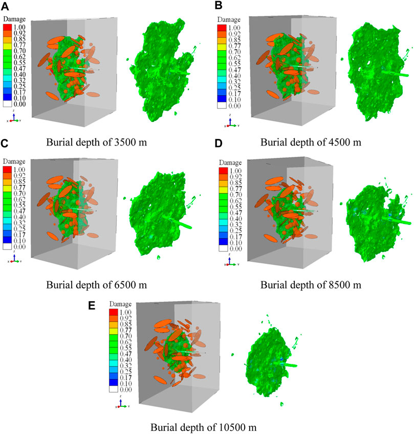
FIGURE 12. Influence of buried depth on the morphology of hydraulic fracture. (A) Burial depth of 3,500 m. (B) Burial depth of 4,500 m. (C) Burial depth of 6,500 m. (D) Burial depth of 8,500 m. (E) Burial depth of 10,500 m.
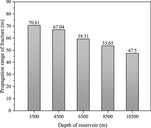
FIGURE 13. Variation of fracture propagation range with reservoir burial depth.
To further examine the discrepancy of the influences of natural fractures and cavities on hydraulic fracture propagation under different burial depth conditions, a horizontal slice of each simulation result is displayed in Figure 14. By comparison, it is found that when the burial depth is relatively shallow (3,500 m, Figure 14A), the impact of geostress compression on fracture propagation is relatively small, and the hydraulic fracture expands sufficiently. The hydraulic fractures can both penetrate and deflect after meeting natural fractures, and then form a larger scale of complex fracture network. With the increase of burial depth (4,500 m–8500 m, Figures 14B–D), the restraint effect of geostress on hydraulic fracture propagation is enhanced, increasing the rock matrix breakage difficulty. The hydraulic fractures tend to deflect and propagate along natural fractures. As the burial depth continues to increase (10500 m, Figure 14E), on the one hand, the increase of geostress limits the propagation range of hydraulic fractures, and Natural fractures are compacted tightly enough to prevent the filtration of low viscosity fracturing fluid into them. Therefore, The trend of hydraulic fractures deflecting when encountering natural fractures will weaken, and the hydraulic fractures tends to penetrate the natural fractures, and the morphology of the hydraulic fractures tend to be simple and short, which is not favorable for connecting more cavities. When the burial depth is 3,500 m, 4,500 m, 6,500 m, 8,500 m, and 10500 m, the number of natural fractures and cavities connected by hydraulic fractures is 34, 30, 24, 17, and 15, respectively, as shown in Figure 15, showing a more obvious decreasing tendency with the increase of burial depth.
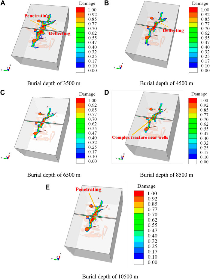
FIGURE 14. Influence of burial depth on hydraulic fracture propagation path. (A) Burial depth of 3,500 m. (B) Burial depth of 4,500 m. (C) Burial depth of 6,500 m. (D) Burial depth of 8,500 m. (E) Burial depth of 10,500 m.
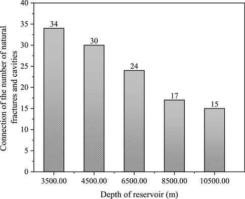
FIGURE 15. The number of natural fractures and cavities connected by hydraulic fractures under different reservoir burial depth.
We summarize the impact of burial depth on hydraulic fracture propagation in Figure 16. It can be concluded that there are two types of cavities that can be relatively easily communicated by hydraulic fractures: cavities located on the main hydraulic fracture propagation path, and cavities closer to the edge of natural fractures have the potential to be connected by hydraulic fractures. These two types of cavities can be further divided into two categories based on their distance from the wellbore. Therefore, each block in Figure 16 is illustrated with four circles representing four categories of cavities. For reservoirs with shallow burial depth (3,500 m), hydraulic fractures have a wide range of expansion and complex morphology, which can communicate with these four types of cavities. As the burial depth increases (4,500 m–8,500 m), the increase in geostress have a negative impact on the expansion of hydraulic fractures. Hydraulic fractures are prone to deflecting rather than penetrating when encountering natural fractures. Therefore, due to the inability to communicate enough natural fractures, or the expansion path being altered by natural fractures, hydraulic fractures cannot communicate with cavities far from the wellbore. When the burial depth increases to 10500 m, hydraulic fractures tend to be short and flat, only able to communicate with hydraulic fractures and cavities closer to the wellbore. Therefore, for deeply buried fracture-cavity reservoirs, adjusting the viscosity of fracturing fluid is no longer meaningful. It is possible to consider increasing the amount of acid to expand the communication range of hydraulic fractures.
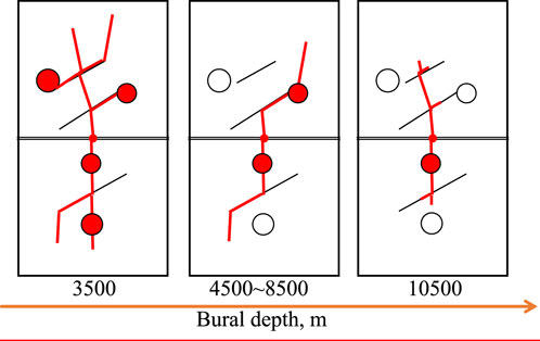
FIGURE 16. Typical features of influence of burial depth on hydraulic fracture morphology.
In this simulation case, the reservoir condition of 8,500 m burial depth is taken, and the pore pressure of 93.5 MPa, vertical geostress of 187 MPa, and maximum horizontal geostress of 176 MPa can be calculated correspondingly. Keeping the injection fracturing fluid pump rate of 2 m3/min and viscosity of 3 mPa·s and the injection time unchanged, the minimum horizontal geostress are taken as 152 MPa, 158 MPa, 164 MPa, 170 MPa, and 176 MPa, to investigate the influence of different geostress differences on hydraulic fracture propagation. The simulation results are shown in Figure 17.
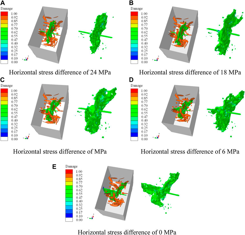
FIGURE 17. Influence of different horizontal stress differences on hydraulic fracture morphology. (A) Horizontal stress difference of 24 MPa, (B) Horizontal stress difference of 18 MPa, (C) Horizontal stress difference of MPa, (D) Horizontal stress difference of 6 MPa, (E) Horizontal stress difference of 0 MPa.
Figure 17 shows the influence of different horizontal stress differences on the hydraulic fracture propagation pattern, and it can be found that when the horizontal stress difference is large, the hydraulic fracture surface stays perpendicular to the direction of the wellbore (Figures 17A, B), and as the horizontal tress difference decreases, the hydraulic fracture surface no longer stays perpendicular to the wellbore during propagation (Figures 17C,D). When the horizontal stress difference is 0, it produces a fracture surface that propagates along the direction of the wellbore in addition to a fracture surface that propagates perpendicular to the wellbore (Figure 17E). Also, horizontal slices of simulation results are displayed to investigate the mechanism of effect of different stress differences, as shown in Figure 18. As can be seen from the figures, at a horizontal stress difference of 24 MPa, hydraulic fracture breaks the rock more easily due to the smaller minimum horizontal stress, and hydraulic fracture can easily penetrate the fracture without being induced by the natural fracture to deflect (Figure 18A). As the minimum horizontal stress increases and the horizontal stress difference decreases, it becomes more difficult to break the rock, and deflection occurs easily when natural fractures are encountered (Figures 13A–C). When natural fractures exist in the vicinity of the wellbore injection hole, it will induce hydraulic fractures to propagate along the wellbore direction, especially when the horizontal stress difference is 0, a complete fracture surface that propagates along the wellbore direction will be develop (Figure 17E; Figure 18E), increased the complexity of hydraulic fracture morphology. It can be seen from the simulation results that the influence of stress differences and natural fractures on the propagation path of hydraulic fractures is similar to that in fractured reservoirs such as shale (Zhou et al., 2010; Hou et al., 2018; Liu et al., 2018). This indirectly proves the effectiveness of the new method in simulating the influence of natural fractures and stress differences on the propagation morphology of hydraulic fractures.
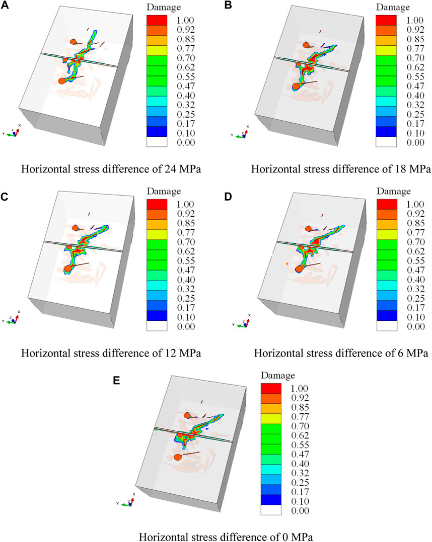
FIGURE 18. Influence of horizontal stress difference on hydraulic fracture propagation path. (A) Horizontal stress difference of 24 MPa, (B) Horizontal stress difference of 18 MPa, (C) Horizontal stress difference of MPa, (D) Horizontal stress difference of 6 MPa, (E) Horizontal stress difference of 0 MPa.
Figure 19 shows the influence of different horizontal stress differences on the hydraulic fracture connecting natural fractures and cavities, and it can be seen that under certain conditions of fracturing fluid injection pump rate and viscosity, high stress differences are beneficial for hydraulic fractures to connect more natural fractures and cavities. The reason for that maybe high stress difference can promote the hydraulic fracture break through the natural fracture barrier, and then connect more natural fractures and cavities, while under conditions of low stress differences, hydraulic fractures are susceptible to natural fractures, and hydraulic energy is captured by natural fractures and cavities near the wellbore, causing limited reservoir stimulation. Another reason for this result may be that under low stress differential conditions, hydraulic fractures tend to bypass cavities, as presented by previous research findings (Cheng et al., 2019; Liu et al., 2019; Kao et al., 2022). Therefore, for fracture-cavity reservoirs, high stress differences are beneficial for improving hydraulic fracturing treatment effects, unlike shale fracturing which prefers low stress differences to increase fracture complexity.
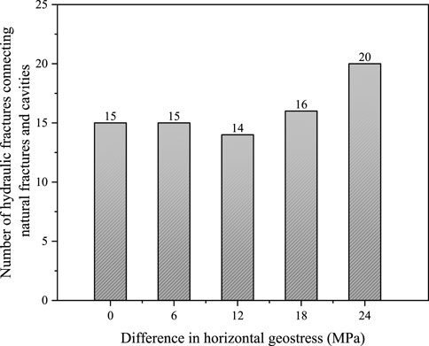
FIGURE 19. Influence of different geostress difference conditions on hydraulic fracture connecting natural fracture and natural cavity.
Create a new set of five models with the same geostress data. For each model, the reservoir burial depth is 8,500 m; the pore pressure is 93.5 MPa; the vertical stress is 187 MPa; the maximum horizontal stress is 176 MPa; the minimum horizontal stress is 164 MPa. To investigate the effect of pump rate on hydraulic fracture morphology, these five models take five different pump rates, 2, 4, 6, 8, and 10 m3/min. And the viscosity of the fracturing fluid is set as 3 mPa·s for all five models.
Figure 20 and Figure 21 show the hydraulic fracture propagation patterns under different pump rates. It can be seen that when the pump rate is increased from 2 m3/min to 4 m3/min, the propagation range of hydraulic fracture increases more obviously, but the hydraulic energy is still insufficient for hydraulic fractures to penetrate the natural fractures (Figure 21B). Thus the morphology of the hydraulic fracture does not change significantly (Figures 21A, B). When the pump rate is increased to 6 m3/min or more, hydraulic fractures not only propagate along natural fractures, but also penetrate them, forming a multi-branched fracture morphology (Figures 21C–E). Typical features of the influence of pump rate on fracture morphology can be illustrated as shown in Figure 22. Figure 23 summarizes the number of natural fractures and cavities connected by hydraulic fractures under different pump rates. As can be seen in, the number of hydraulic fractures connecting natural fractures and cavities increases significantly when the discharge rate is increased from 4 m3/min to 6 m3/min. Whereas the pump rate increases to greater than 6 m3/min, the increase in the number of hydraulic fractures connecting natural fractures and cavities is not obvious, which may be related to the scale of the model (Figure 23). In summary, under existing geological and engineering conditions set in this simulation case, in order to connect hydraulic fractures with as many natural fractures and cavities as possible, the fracturing fluid pump rate should be at least 6 m3/min per cluster.
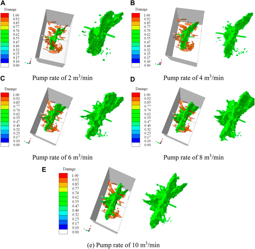
FIGURE 20. Morphology of hydraulic fracture under different fracturing fluid pump rates. (A) Pump rate of 2 m3/min, (B) Pump rate of 4 m3/min, (C) Pump rate of 6 m3/min, (D) Pump rate of 8 m3/min, (E) Pump rate of 10 m3/min.
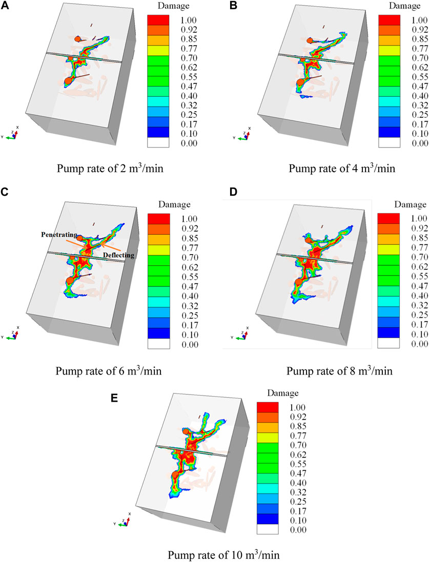
FIGURE 21. Influence of different fracturing fluid pump rates on the fracture propagation path. (A) Pump rate of 2 m3/min, (B) Pump rate of 4 m3/min, (C) Pump rate of 6 m3/min, (D) Pump rate of 8 m3/min, (E) Pump rate of 10 m3/min.
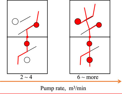
FIGURE 22. Typical features of the influence of pump rate on fracture morphology.
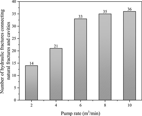
FIGURE 23. The number of natural fractures and cavities connected by hydraulic fractures under different pump rates.
In this simulation case, the burial depth is set as 8,500 m; pore pressure is 93.5 MPa; vertical stress is 187 MPa; maximum horizontal stress is 176 MPa; minimum horizontal stress is 164 MPa; the pump rate is 2 m3/min. And five different viscosities of fracturing fluid for five models are taken to exam the influence of fracturing fluid viscosity on hydraulic fracture morphology, they are 3, 30, 100, 150, and 200 mPa·s.
Figure 24 and Figure 25 show the influence of fracturing fluid viscosity on the hydraulic fracture propagation pattern. It can be found that when the viscosity of the fracturing fluid is very low (3 mPa·s), the fracturing fluid is heavily lost into the natural fractures when the hydraulic fractures meet the natural fractures, inducing the hydraulic fractures to deflect and propagate along the natural fractures (Figure 25A). As the viscosity of the fracturing fluid increases, the seepage coefficient of the fracturing fluid in the natural fracture becomes lower, and the tendency of the hydraulic fracture to deflect along the natural fracture is weakened, which is conducive to hydraulic fractures penetrating natural fractures. Overall as the viscosity of the fracturing fluid increases, the hydraulic fracture morphology becomes more and more flat and perpendicular to the wellbore (Figure 24). Especially when the viscosity of the fracturing fluid exceeds 150 mPa·s, the hydraulic fracture meets the natural fracture and penetrates directly, and the influence of the hydraulic fracture on the propagation path of the natural fracture is already very small (Figures 25D, E). Typical features of the influence of fracture fluid viscosity on hydraulic fracture morphology is summarized in Figure 26, form which, it can be seen that the hydraulic fracture morphology undergoes a transition from simple to complex, and then to simple with the change the fracturing fluid viscosity from low to high. Also, It is worth noting that through the statistics of the number of natural fractures and cavities connected by hydraulic fracture under different fracturing fluid viscosities, either too high or too low viscosity of the fracturing fluid is not conducive to the connection of more natural fractures and cavities by hydraulic fractures. But there exists an optimum viscosity interval, where the viscosity of fracturing fluid is not too high to ensure the expansion of hydraulic fractures along natural fractures, nor too low to ensure that hydraulic fractures can penetrate natural fractures. In this simulation case, the optimal viscosity of the fracturing fluid is 30 mPa·s. Under this viscosity condition, the hydraulic fractures can not only propagate along the natural fractures, but also penetrate of the natural fractures (Figure 26), which is beneficial to connect more natural fractures and the cavities (Figure 27).
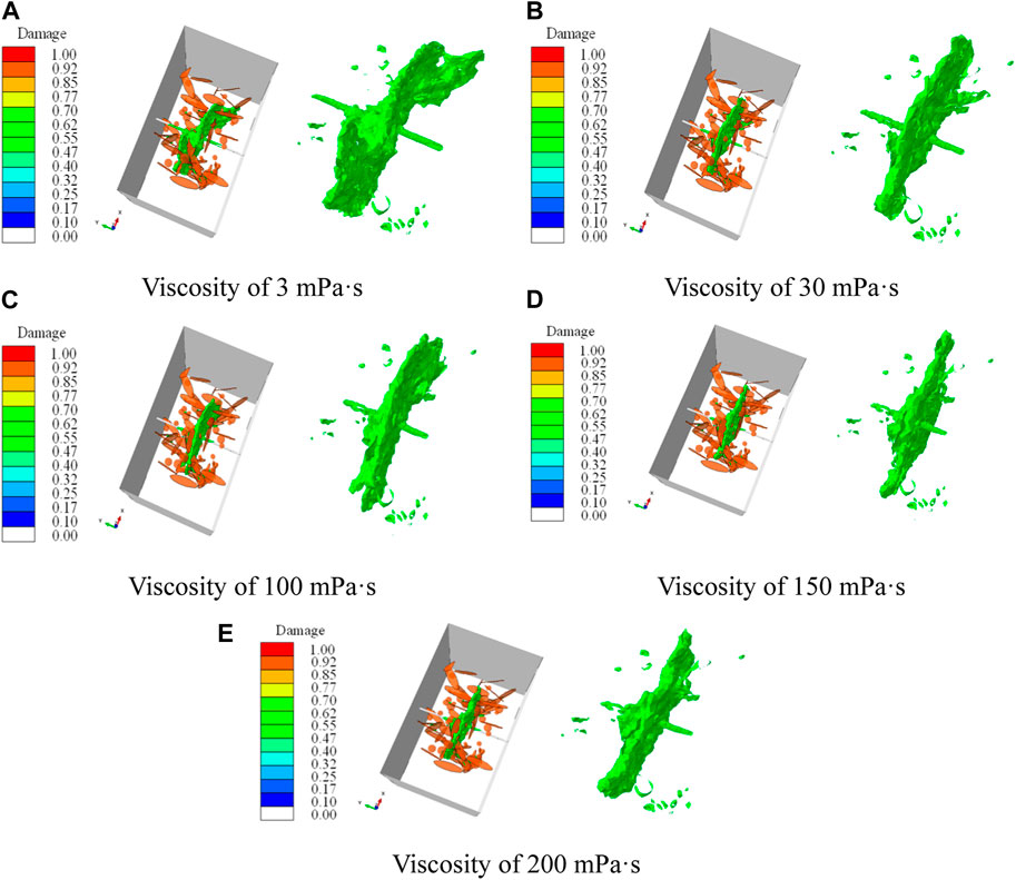
FIGURE 24. Influence of different fracturing fluid viscosities on hydraulic fracture morphology. (A) Viscosity of 3 mPa·s, (B) Viscosity of 30 mPa·s, (C) Viscosity of 100 mPa·s, (D) Viscosity of 150 mPa·s, (E) Viscosity of 200 mPa·s.
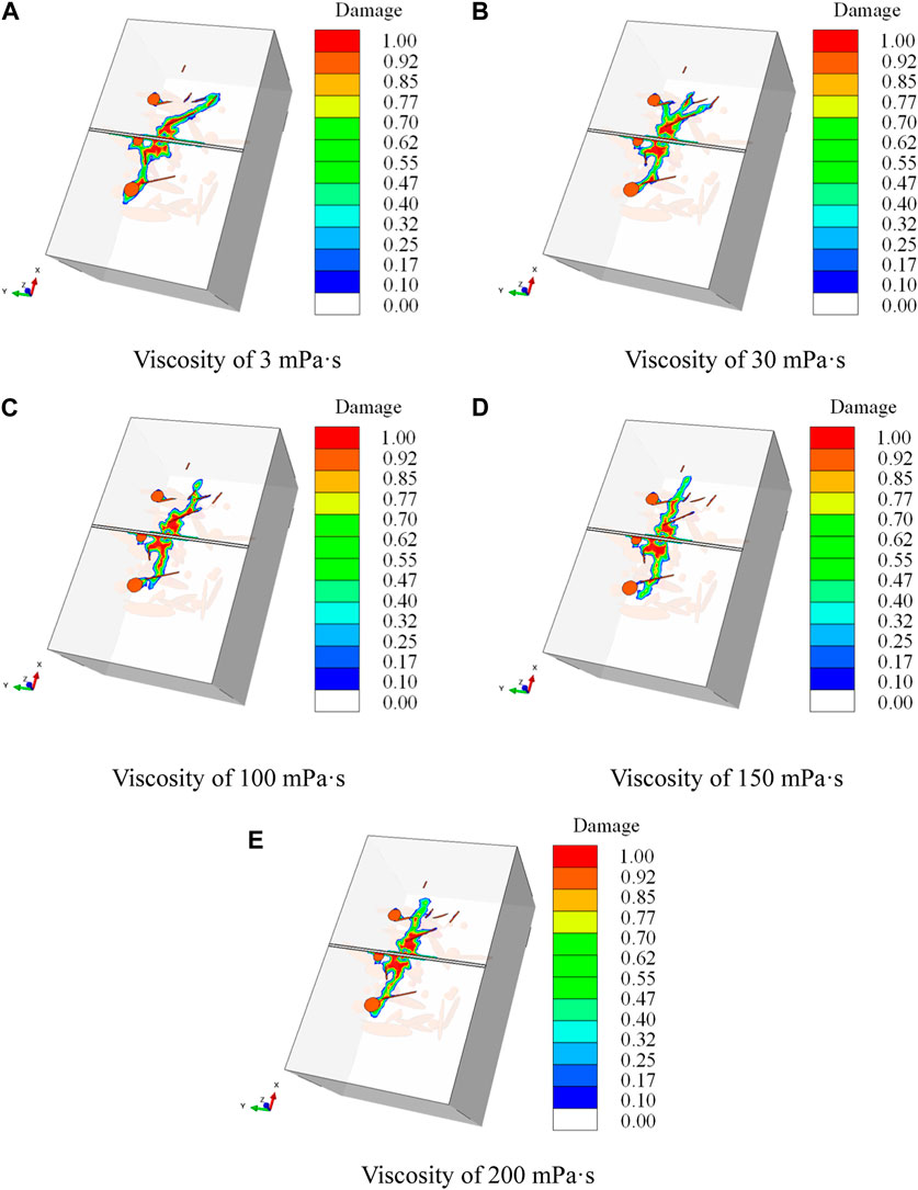
FIGURE 25. Influence of fracturing fluid viscosity on hydraulic fracture propagation paths. (A) Viscosity of 3 mPa·s, (B) Viscosity of 30 mPa·s, (C) Viscosity of 100 mPa·s, (D) Viscosity of 150 mPa·s, (E) Viscosity of 200 mPa·s.
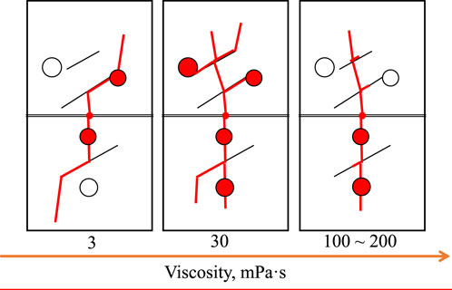
FIGURE 26. Typical features of the influence of fracture fluid viscosity on hydraulic fracture morphology.
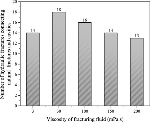
FIGURE 27. The number of hydraulic fractures connecting natural fractures and natural cavities under different fracturing fluid viscosity conditions.
From the above simulation results, it can be seen that the new simulation method proposed in this paper can break through the limitation of the physical simulation experiment size, and also overcome the limitations of the traditional numerical simulation methods with plane assumption. The simulation method based on continuous damage can better simulate the influence of natural fractures and cavities on hydraulic fractures under different conditions of geostress, fracturing fluid viscosity and pump rate, and is in good agreement with the results observed in previous physical simulation experiments. Based on the advantages of the simulation methodology in this paper, some relatively new or different results have been achieved compared to previous work in the following areas. Firstly, the new method overcomes the limitations of traditional numerical simulation methods that only study the influence of a single cavity on the hydraulic fracture propagation path. The discrete fracture modeling method is used to establish a model with randomly distributed natural fractures and cavities that is closer to the actual reservoir situation. Secondly, the influence of burial depth on the propagation range and morphology of fractures is investigated. Previous studies on the influence of geostress on the morphology of fractures were mostly confined to the influence of the geostress difference on the morphology of fractures at a certain burial depth, while actually the increase of the burial depth also has a significant influence on the morphology of fractures. Finally, evaluating the influence of geological and engineering factors on fracturing effectiveness by counting the number of hydraulic fractures connecting natural fractures and cavities in the simulation results, some meaningful conclusions can be quantitatively obtained.
Due to the assumptions and simplifications in the model in geologic modeling, such as the geometry, size, and distribution data of natural fractures and cavities, the model does not consider the real morphology of fractures and cavities, nor does it consider the variability of the mechanical and seepage properties of natural fractures and cavities during their formation, which differs greatly from the real situation. Thus, the conclusions obtained from the model in this paper can be used as a qualitative reference, and if the model is applied in the field practice, it needs to be combined with specific reservoir parameters to carry out more detailed modeling. This also provides a direction for the subsequent improvement work. That is, on the one hand, strive to obtain more accurate information on the real size and spatial distribution of the natural fractures and cavities; on the other hand, take into account the variation of the mechanical and seepage properties of the fractures and cavities, to make the simulation conditions more closer to the field.
In this paper, a finite element model for the propagation of hydraulic fracture propagation under the influence of natural fracture and cavity in a fracture-cavity carbonate reservoir was established based on the continuum damage theory. The model was validated against previous experimental results obtained by other researchers. Based on this model, the influences of burial depth, geostress difference, and fracturing fluid pump rate and viscosity on the hydraulic fracture propagation pattern were investigated, and the following conclusions were obtained:
(1) The burial depth of reservoir affects the ability of hydraulic fracture to penetrate natural fracture. When the burial depth is small (3,500 m), the hydraulic fractures can both penetrate and deflect after meeting natural fractures. With the increase of burial depth (4,500 m–8,500 m), the restraint effect of geostress on hydraulic fracture propagation is enhanced, hydraulic fractures tend to deflect and propagate along natural fractures. As the burial depth continues to increase (10500 m), natural fractures are compacted tightly enough to prevent the filtration of low viscosity fracturing fluid into them, the hydraulic fractures tends to penetrate the natural fractures, and the morphology of the hydraulic fractures tend to be simple and short.
(2) The horizontal stress difference has impact on the fracture morphology and the connection of hydraulic fractures with natural fractures and cavities. When the maximum horizontal stress is fixed, as the minimum horizontal stress increases and the horizontal stress difference decreases, it becomes more difficult for hydraulic fractures to break the rock, and the deflection occurs easily when natural fractures are encountered. What’s more, high horizontal stress differences are beneficial for hydraulic fractures to connect more natural fractures and cavities.
(3) The fracture fluid pump rate has significant effect on the connection of hydraulic fractures with natural fractures and cavities. With the increase of fracturing fluid pump rate, the ability of hydraulic fracture to penetrate the natural fractures is enhanced, also the propagation range and complexity of the hydraulic fractures are increased, promoting hydraulic fractures to connect more natural fractures and cavities.
(4) The fluid viscosity has significant influence on the hydraulic fracture morphology. The hydraulic fracture morphology can undergo a transition from simple to complex, and then to simple with the change of the fracturing fluid viscosity from low to high. However, either too high or too low viscosity of the fracturing fluid is not conducive to the connection of more natural fractures and cavities by hydraulic fractures. There exists an optimum viscosity interval, where the viscosity of fracturing fluid is not too high to ensure the expansion of hydraulic fractures along natural fractures, nor too low to ensure that hydraulic fractures can penetrate natural fractures.
(5) The modelling method introduced in this article can examine the influence of reservoir heterogeneity caused by the presence of fractures and cavities, as well as different geological and engineering factors on the morphology of hydraulic fracture propagation. This method can be used for hydraulic fracturing design of treatment of fracture-cavity carbonate reservoirs.
The original contributions presented in the study are included in the article/supplementary material, further inquiries can be directed to the corresponding author.
HL: Supervision, Writing–review and editing. ML: Investigation, Writing–original draft. QS: Funding acquisition, Methodology, Writing–original draft. YJ: Supervision, Writing–review and editing. BL: Investigation, Writing–review and editing. CW: Investigation, Writing–review and editing. XC: Investigation, Writing–review and editing.
The author(s) declare that financial support was received for the research, authorship, and/or publication of this article. This research was funded by the National Natural Science Foundation of China (No. 52204042) and the Shandong Provincial Natural Science Foundation, China (Nos. ZR2021QE154 and ZR2019ZD14).
The authors declare that the research was conducted in the absence of any commercial or financial relationships that could be construed as a potential conflict of interest.
All claims expressed in this article are solely those of the authors and do not necessarily represent those of their affiliated organizations, or those of the publisher, the editors and the reviewers. Any product that may be evaluated in this article, or claim that may be made by its manufacturer, is not guaranteed or endorsed by the publisher.
Busetti, S., Mish, K., Hennings, P., et al. (2012b). Damage and plastic deformation of reservoir rocks; Part 1, Damage fracturing. AAPG Bull. 96 (9), 1687–1709. doi:10.1306/02011211011
Busetti, S., Mish, K., and Reches, Z. (2012a). Damage and plastic deformation of reservoir rocks; Part 1, Damage fracturing. AAPG Bull. 96 (9), 1687–1709. doi:10.1306/02011211010
Chalikakis, K., Plagnes, V., Guerin, R., Valois, R., and Bosch, F. P. (2011). Contribution of geophysical methods to karst-system exploration: an overview. Hydrogeology J. 19 (6), 1169–1180. doi:10.1007/s10040-011-0746-x
Cheng, L., Luo, Z. F., Yu, Y., Zhao, L., and Zhou, C. (2019). Study on the interaction mechanism between hydraulic fracture and natural karst cave with the extended finite element method. Eng. Fract. Mech. 222, 106680. doi:10.1016/j.engfracmech.2019.106680
Chuprakov, D., Melchaeva, O., and Prioul, R. (2013). Hydraulic fracture propagation across a weak discontinuity controlled by fluid injection. ISRM Int. Conf. Eff. Sustain. hydraulic Fract. ISRM-ICHF-2013-2008. doi:10.5772/55941
Detoumay, E., and Cheng, A. H. D. (1993). Fundamentals of poroelasticity. Analysis Des. Methods 2 (1), 113–171. doi:10.1016/B978-0-08-040615-2.50011-3
Drucke, D. C., and Prager, W. (1952). Soil mechanics and plastic analysis or limit design. Q. Appl. Math. 10 (2), 157–165. doi:10.1090/qam/48291
Guo, T. K., Tang, S. J., Liu, S., Liu, X., Xu, J., Qi, N., et al. (2021). Physical simulation of hydraulic fracturing of large-sized tight sandstone outcrops. Spe J. 26 (1), 372–393. doi:10.2118/204210-PA
He, R., Yang, J., Li, L., Yang, Z., Chen, W., Zeng, J., et al. (2023). Investigating the simultaneous fracture propagation from multiple perforation clusters in horizontal wells using 3D block discrete element method. Front. Earth Sci. 11, 1115054. doi:10.3389/feart.2023.1115054
Hibbitt, H. D., Karlsson, B. I., and Sorensen, E. P. (2016). Abaqus/CAE user’s guide. Providence, RI: Dassault Systemes Simulia Corp. Available at: https://ceae-server.colorado.edu/v2016/books/usi/default.htm.
Hillerborg, A., Modeer, M., and Peterson, P. E. (1976). Analysis of crack formation and crack growth in concrete by means of fracture mechanics and finite elements. Cem. Concr. Res. 6 (6), 773–781. doi:10.1016/0008-8846(76)90007-7
Hou, B., Zhang, R. X., Tan, P., Song, Y., Fu, W., Chang, Z., et al. (2018). Characteristics of fracture propagation in compact limestone formation by hydraulic fracturing in central Sichuan, China. J. Nat. Gas Sci. Eng. 57, 122–134. doi:10.1016/j.jngse.2018.06.035
Huang, L., Dontsov, E., Fu, H., Lei, Y., Weng, D., and Zhang, F. (2022). Hydraulic fracture height growth in layered rocks: perspective from DEM simulation of different propagation regimes. Int. J. Solids Struct. 238, 111395. doi:10.1016/j.ijsolstr.2021.111395
Huang, L., He, R., Yang, Z., Tan, P., Chen, W., Li, X., et al. (2023b). Exploring hydraulic fracture behavior in glutenite formation with strong heterogeneity and variable lithology based on DEM simulation. Eng. Fract. Mech. 278, 109020. doi:10.1016/j.engfracmech.2022.109020
Huang, L., Liu, J., Ji, Y., Gong, X., and Qin, L. (2018). A review of multiscale expansion of low permeability reservoir cracks. Petroleum 4, 115–125. doi:10.1016/j.petlm.2017.09.002
Huang, L., Liu, J., Zhang, F., Dontsov, E., and Damjanac, B. (2019). Exploring the influence of rock inherent heterogeneity and grain size on hydraulic fracturing using discrete element modeling. Int. J. Solids Struct. 176, 207–220. doi:10.1016/j.ijsolstr.2019.06.018
Huang, L., Liu, J., Zhang, F., Fu, H., Zhu, H., and Damjanac, B. (2020). 3D lattice modeling of hydraulic fracture initiation and near-wellbore propagation for different perforation models. J. Petroleum Sci. Eng. 191, 107169. doi:10.1016/j.petrol.2020.107169
Huang, L., Tan, J., Fu, H., Liu, J., Chen, X., Liao, X., et al. (2023a). The non-plane initiation and propagation mechanism of multiple hydraulic fractures in tight reservoirs considering stress shadow effects. Eng. Fract. Mech. 292, 109570. doi:10.1016/j.engfracmech.2023.109570
Ji, Y., Wang, J., and Huang, L. (2015). Analysis on inflowing of the injecting Water in faulted formation. Adv. Mech. Eng. 7, 1–10. doi:10.1177/1687814015590294
Jiao, F. Z. (2019). Practice and knowledge of volumetric development of deep fractured-vuggy carbonate reservoirs in Tarim Basin, NW China. Petroleum Explor. Dev. 46 (3), 576–582. doi:10.1016/S1876-3804(19)60037-6
Kao, J. W., Wei, S. M., Wang, W. Z., and Jin, Y. (2022). Numerical analysis of the hydraulic fracture communication modes in fracture-cavity reservoirs. Petroleum Sci. 19 (5), 2227–2239. doi:10.1016/j.petsci.2022.05.011
Liu, B. H., Jin, Y., and Chen, M. (2019). Influence of vugs in fractured-vuggy carbonate reservoirs on hydraulic fracture propagation based on laboratory experiments. J. Struct. Geol. 124, 143–150. doi:10.1016/j.jsg.2019.04.007
Liu, Q., Li, J., Liang, B., Liu, J., Sun, W., He, J., et al. (2023). Complex wettability behavior triggering mechanism on imbibition: a model construction and comparative study based on analysis at multiple scales. Energy 275, 127434. doi:10.1016/j.energy.2023.127434
Liu, Z., Wang, S., Zhao, H., Wang, L., Li, W., Geng, Y., et al. (2018). Effect of random natural fractures on hydraulic fracture propagation geometry in fractured carbonate rocks. Rock Mech. Rock Eng. 51 (2), 491–511. doi:10.1007/s00603-017-1331-y
Liu, Z. Y., Tang, X. H., Tao, S., Zhang, G., and Chen, M. (2020). Mechanism of connecting natural caves and wells through hydraulic fracturing in fracture-cavity reservoirs. Rock Mech. Rock Eng. 53 (12), 5511–5530. doi:10.1007/s00603-020-02225-w
Luo, H., Xie, J., Huang, L., Wu, J., Shi, X., Bai, Y., et al. (2022). Multiscale sensitivity analysis of hydraulic fracturing parameters based on dimensionless analysis method. Lithosphere 2022, 9708300. doi:10.2113/2022/9708300
Luo, Z., Zhang, N., Zhao, L., Zeng, J., and Liu, P. (2020). Interaction of a hydraulic fracture with a hole in poroelasticity medium based on extended finite element method. Eng. analysis Bound. Elem. 115, 108–119. doi:10.1016/j.enganabound.2020.03.011
Lv, A., Yao, J., and Wang, W. (2011). Characteristics of oil-water relative permeability and influence mechanism in fractured-vuggy medium. Procedia Eng. 18, 175–183. doi:10.1016/j.proeng.2011.11.028
Mousavi, M., Prodanovic, M., and Jacobi, D. (2013). New classification of carbonate rocks for process-based pore-scale modeling. Spe J. 18 (2), 243–263. doi:10.2118/163073-PA
Qiao, J., Tang, X., Hu, M., Rutqvist, J., and Liu, Z. (2022). The hydraulic fracturing with multiple influencing factors in carbonate fracture-cavity reservoirs. Comput. Geotechnics 147, 104773. doi:10.1016/j.compgeo.2022.104773
Rahm, D. (2011). Regulating hydraulic fracturing in shale gas plays: the case of Texas. Energy Policy 39 (5), 2974–2981. doi:10.1016/j.enpol.2011.03.009
Ren, Q. Q., Jin, Q., Feng, J. W., and Du, H. (2020). Design and construction of the knowledge base system for geological outfield cavities classifications: an example of the fracture-cavity reservoir outfield in Tarim basin, NW China. J. Petroleum Sci. Eng. 194, 107509. doi:10.1016/j.petrol.2020.107509
Shan, Q. L., Jin, Y., Tan, P., and Zhang, R. (2018). Experimental and numerical investigations on the vertical propagation of hydraulic fractures in laminated shales. J. Geophys. Eng. 15 (4), 1729–1742. doi:10.1088/1742-2140/aac12f
Song, R., Liu, J., and Cui, M. (2017). A new method to reconstruct structured mesh model from micro-computed tomography images of porous media and its application. Int. J. Heat Mass Transf. 109, 705–715. doi:10.1016/j.ijheatmasstransfer.2017.02.053
Song, R., Wang, Y., Ishutov, S., Zambrano-Narvaez, G., Hodder, K. J., Chalaturnyk, R. J., et al. (2020). A comprehensive experimental study on mechanical behavior, microstructure and transport properties of 3D-printed rock analogs. Rock Mech. Rock Eng. 53, 5745–5765. doi:10.1007/s00603-020-02239-4
Tan, P., Fu, S., Chen, Z., and Zhao, Q. (2023). Experimental investigation on fracture growth for integrated hydraulic fracturing in multiple gas bearing formations. Geoenergy Sci. Eng. 231, 212316. doi:10.1016/j.geoen.2023.212316
Tan, P., Jin, Y., Han, K., Hou, B., Chen, M., Guo, X., et al. (2017). Analysis of hydraulic fracture initiation and vertical propagation behavior in laminated shale formation. Fuel 206, 482–493. doi:10.1016/j.fuel.2017.05.033
Tan, P., Jin, Y., and Pang, H. (2021). Hydraulic fracture vertical propagation behavior in transversely isotropic layered shale formation with transition zone using XFEM-based CZM method. Eng. Fract. Mech. 248, 107707. doi:10.1016/j.engfracmech.2021.107707
Tan, P., Pang, H., Zhang, R., Jin, Y., Zhou, Y., Kao, J., et al. (2020). Experimental investigation into hydraulic fracture geometry and proppant migration characteristics for southeastern Sichuan deep shale reservoirs. J. Petroleum Sci. Eng. 184, 106517. doi:10.1016/j.petrol.2019.106517
Tang, C. A., Tham, L. G., Lee, P. K. K., Yang, T., and Li, L. (2002). Coupled analysis of flow, stress and damage (FSD) in rock failure. Int. J. Rock Mech. Min. Sci. 39 (4), 477–489. doi:10.1016/S1365-1609(02)00023-0
Tian, F., Luo, X., and Zhang, W. (2019). Integrated geological-geophysical characterizations of deeply buried fractured-vuggy carbonate reservoirs in Ordovician strata, Tarim Basin. Mar. Petroleum Geol. 99, 292–309. doi:10.1016/j.marpetgeo.2018.10.028
Wang, B., Liu, X., Sima, L., et al. (2019). Grading evaluation and prediction of fracture-cavity reservoirs in cambrian longwangmiao formation of moxi area, sichuan basin, SW China. Petrol. explor. Dev. 46 (2), 301–313. doi:10.1016/S1876-3804(19)60010-8
Wang, H., Tang, X., Luo, Z., et al. (2018). Investigation of the fracture propagation in fractured-vuggy reservoirs. ARMA US Rock Mechanics/Geomechanics Symposium.
Wang, H. Y. (2019). Hydraulic fracture propagation in naturally fractured reservoirs: complex fracture or fracture networks. J. Nat. Gas Sci. Eng. 68, 102911. doi:10.1016/j.jngse.2019.102911
Wu, M., Jiang, C., Song, R., Liu, J., Li, M., Liu, B., et al. (2023). Comparative study on hydraulic fracturing using different discrete fracture network modeling: insight from homogeneous to heterogeneity reservoirs. Eng. Fract. Mech. 284, 109274. doi:10.1016/j.engfracmech.2023.109274
Xiao, Z., Li, M., Huang, S., Wang, T., Zhang, B., Fang, R., et al. (2016). Source, oil charging history and filling pathways of the Ordovician carbonate reservoir in the Halahatang Oilfield, Tarim Basin, NW China. Mar. Petrol. Geol. 73, 59–71. doi:10.1016/j.marpetgeo.2016.02.026
Xu, B., and Wong, R. C. K. (2010). A 3D finite element model for history matching hydraulic fracturing in unconsolidated sands formation. J. Can. Petroleum Technol. 49 (04), 58–66. doi:10.2118/2009-100
Xu, C., Di, B., and Wei, J. (2016). A physical modeling study of seismic features of karst cave reservoirs in the Tarim Basin, China. Geophysics 81 (1), B31–B41. doi:10.1190/geo2014-0548.1
Zhang, F., Damjanac, B., and Maxwell, S. (2019). Investigating hydraulic fracturing complexity in naturally fractured rock masses using fully coupled multiscale numerical modeling. Rock Mech. Rock Eng. 52, 5137–5160. doi:10.1007/s00603-019-01851-3
Zhang, F., Dontsov, E., and Mack, M. (2017). Fully coupled simulation of a hydraulic fracture interacting with natural fractures with a hybrid discrete-continuum method. Int. J. Numer. Anal. Methods Geomechanics 41 (13), 1430–1452. doi:10.1002/nag.2682
Zhang, F., Huang, L., Yang, L., Dontsov, E., Weng, D. W., Liang, H. B., et al. (2022). Numerical investigation on the effect of depletion-induced stress reorientation on infill well hydraulic fracture propagation. Petroleum Sci. 19 (1), 296–308. doi:10.1016/j.petsci.2021.09.014
Zhang, K., and Wang, D. (2004). Types of karst-fractured and porous reservoirs in China's carbonates and the nature of the Tahe oilfield in the Tarim Basin. Acta Geol. Sinica-English Ed. 78 (3), 866–872. doi:10.1111/j.1755-6724.2004.tb00208.x
Zheng, S., Min, Y., Kang, Z., Liu, Z., Long, X., Liu, K., et al. (2019). Controlling factors of remaining oil distribution after water flooding and enhanced oil recovery methods for fracturecavity carbonate reservoirs in Tahe Oilfield. Petroleum Explor. Dev. 46 (4), 786–795. doi:10.1016/s1876-3804(19)60236-3
Zheng, Y., He, R., Huang, L., Bai, Y., Wang, C., Chen, W., et al. (2022). Exploring the effect of engineering parameters on the penetration of hydraulic fractures through bedding planes in different propagation regimes. Comput. Geotechnics 146, 104736. doi:10.1016/j.compgeo.2022.104736
Zhou, J., Jin, Y., and Chen, M. (2010). Experimental investigation of hydraulic fracturing in random naturally fractured blocks. Int. J. Rock Mech. Min. Sci. 47 (7), 1193–1199. doi:10.1016/j.ijrmms.2010.07.005
Keywords: fracture-cavity carbonate reservoir, hydraulic fracturing, fracture propagation, continuous damage theory, numerical simulation
Citation: Luan H, Liu M, Shan Q, Jiang Y, Li B, Wang C and Cheng X (2024) Numerical study of hydraulic fractures propagation in deep fracture-cavity reservoir based on continuous damage theory. Front. Energy Res. 12:1377400. doi: 10.3389/fenrg.2024.1377400
Received: 27 January 2024; Accepted: 26 February 2024;
Published: 07 March 2024.
Edited by:
Liuke Huang, Southwest Petroleum University, ChinaReviewed by:
Yuqiang Xu, China University of Petroleum, ChinaCopyright © 2024 Luan, Liu, Shan, Jiang, Li, Wang and Cheng. This is an open-access article distributed under the terms of the Creative Commons Attribution License (CC BY). The use, distribution or reproduction in other forums is permitted, provided the original author(s) and the copyright owner(s) are credited and that the original publication in this journal is cited, in accordance with accepted academic practice. No use, distribution or reproduction is permitted which does not comply with these terms.
*Correspondence: Qinglin Shan, c2hhbnFpbmdsaW4yMDAwQDE2My5jb20=
Disclaimer: All claims expressed in this article are solely those of the authors and do not necessarily represent those of their affiliated organizations, or those of the publisher, the editors and the reviewers. Any product that may be evaluated in this article or claim that may be made by its manufacturer is not guaranteed or endorsed by the publisher.
Research integrity at Frontiers
Learn more about the work of our research integrity team to safeguard the quality of each article we publish.