- College of Nuclear Science and Technology, Naval University of Engineering, Wuhan, China
Introduction: The main gate valve is a critical component of the coolant system in marine nuclear power plants, yet its integrity is often compromised by leakage, particularly during transient operations. This study employs a fluid-solid-thermal coupling method to numerically investigate the sealing performance of the main gate valve under rapid coolant temperature drops.
Methods: The analysis reveals that thermal shock-induced uneven stress and deformation significantly reduce contact pressure on the sealing surface, leading to leakage.
Results and Discussion: Notably, only when the bolt preload reaches the material yield limit can the valve maintain a seal during operation. Furthermore, the study demonstrates that a faster rate of coolant temperature drop exacerbates the leakage. These findings offer valuable insights for optimizing the operation of marine nuclear power plants and enhancing the structural integrity of the main gate valve.
1 Introduction
This study focuses on a marine pressurized water reactor (PWR) equipped with a two-loop cooling system, specifically investigating the main gate valve within the primary loop. According to the typical design scheme of marine nuclear power plant, the coolant system is generally equipped with the main gate valve, which is normally open in normal operation and can be closed to cut off the coolant flow in the pipeline when needed. In actual operation, the main gate valve is in high temperature, high pressure and frequently changing operating conditions for a long time, the integrity of its structure is easily impacted, resulting in coolant leakage. The actual operating data of the marine nuclear power plant shows that the leakage of the main gate valve flange sealing surface has occurred many times, especially under the transient operating conditions with drastic changes in temperature and pressure, the leakage phenomenon is serious. The leakage of the main gate valve flange sealing surface has also become a typical problem that affects the safe operation of nuclear power plants for a long time (Marek and Okrajni, 2013).
The leakage of the gate valve is closely related to its flow heat transfer characteristics and structural mechanical properties (Chen et al., 2018). Researchers commonly use numerical simulation and experimental methods to obtain the various characteristics of the gate valve. Chen et al. (2021) studied the eccentric jet-flow characteristics induced by a gate valve considering the influence of valve opening regulation by experimental and numerical simulation methods, and the generation mechanism of eccentric jet-flow was revealed as a strong pressure gradient caused by the throttling effect at the valve throat. Liu et al. (2019) studied the fluid characteristics via Computational Fluid Dynamics (CFD) method to simulate the flow field inside a gate valve, and proposed an optimization method for subsea gate valve based on combined analysis of fluid characteristics and sensitivity. Lin et al. (2022) performed CFD analysis of flow resistance characteristics and the internal flow characteristics of gate valve in a gate valve with different inlet velocity, and then conducted experimental measurements of the flow resistance characteristics. The CFD simulated flow resistance results show a good agreement with that of experimental flow resistance by comparison. Hu et al. (2016) investigated the flow and conjugate heat transfer characteristics of the underwater gate valve by 3D steady RANS CFD approach (Bazsó and Hős, 2013). Different schemes of turbulence models are adopted in simulations. An underwater gate valve heat transfer experiment verified that the k–ε turbulence model is the most appropriate numerical scheme to solve the underwater conjugate heat transfer problem. He et al. (2019) found the stress concentration zone and maximum deformation zone of gate valve at working pressure according to strength calculation and analysis by ANSYS software, and then revealed the influence law of each design variable on the gate valve body equivalent stress (Hwang et al., 2017). The above research on the flow characteristics, heat transfer characteristics and structural mechanical properties of the main gate valve has been very in-depth. However, the coupling effect between various characteristics has been little studied, especially there is no research on the influence of this coupling effect on the sealing performance of the main gate valve.
In order to study the influence of the coupling effect between the flow characteristics, heat transfer characteristics and structural mechanical properties of the main gate valve, this paper takes a transient operating condition that causes leakage of the main gate valve during the actual operation of the marine nuclear power plant as the background, and uses finite element analysis software ANSYS Workbench 19.0 to numerically simulate the flow characteristics, heat transfer characteristics and sealing performance of the main gate valve based on the fluid-solid-thermal multi-physics field coupling method, and studies the causes of main gate valve leakage and the factors affecting sealing performance.
2 Numerical method
2.1 Analysis process
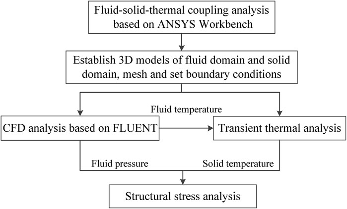
At present, the numerical simulation method of fluid-solid thermal coupling has been applied in many engineering fields, and its accuracy has been verified (Dai et al., 2021; Ma et al., 2022; Wang et al., 2022; Tang et al., 2022). In this paper, the fluid-solid-thermal coupling analysis process based on ANSYS Workbench 19.0 is developed according to the actual operating conditions of the main gate valve (Yu et al., 2022; Yu et al., 2023). Since the material stiffness of the main gate valve is large, its deformation has very little effect on the flow field, so the one-way coupling method is adopted in this paper. Figure 1 shows the solution process. The main steps are as follows:
(1) The physical model of solid domain and the internal fluid domain of the main gate valve are established and meshed, and the fluid-solid interface (FSI) where the solid domain and fluid domain exchange energy is created. The boundary conditions are set according to the actual operating conditions.
(2) The pressure and temperature of fluid domain is calculated by the CFD simulation software FLUENT.
(3) The fluid temperature data are transferred to the transient thermal analysis module to solve the solid temperature through the FSI.
(4) The fluid pressure from the FSI and the temperature obtained from the thermal analysis are transferred to the structural stress analysis module as loads. Meanwhile, the constraints are set to solve for the contact pressure of the main gate valve.
2.2 Numerical model
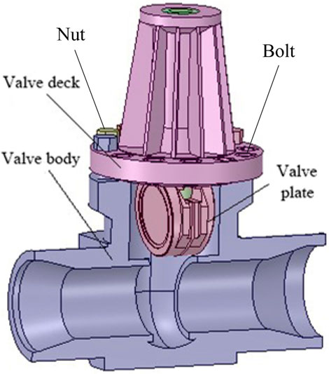
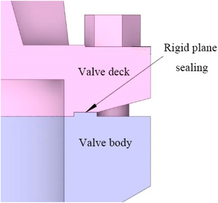
The main gate valve in marine nuclear power plant is generally a fully sealed electric gate valve, whose main components are valve body, valve deck and resilient wedge-shaped valve plate. The flange connection between the valve body and the valve deck adopts a rigid plane sealing structure to prevent the leakage of media. When establishing the three-dimensional geometric model of the main gate valve, it should accurately reflect the actual situation of the structure, and at the same time, the model should be simplified as much as possible to improve the mesh quality and accelerate the simulation convergence under the premise of ensuring the computational accuracy. By simplifying some structural details such as sharp corners and tabs that do not affect fluid flow and complex parts, the geometric model and sealing structure are obtained as shown in Figures 2, 3. The material parameters of each component in the main gate valve model are shown in Table 1.
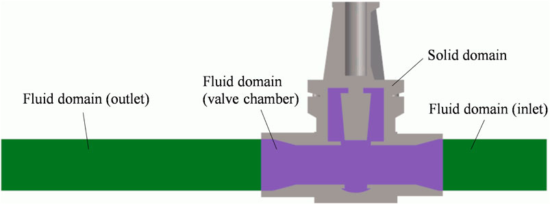
In the CFD simulation, the overall calculation domain of the main gate valve is shown in Figure 4. The calculation domain is divided into solid domain (valve body) and fluid domain (inner chamber) according to the material characteristics, where the fluid domain is divided into inlet part, valve chamber part and outlet part. In order to obtain the full development of turbulence in the inlet section of the valve and to reduce the influence of the outlet, a section of pipe of the same diameter is added to the inlet and outlet of the valve, and the length is 3 times and 5 times of the pipe diameter respectively.
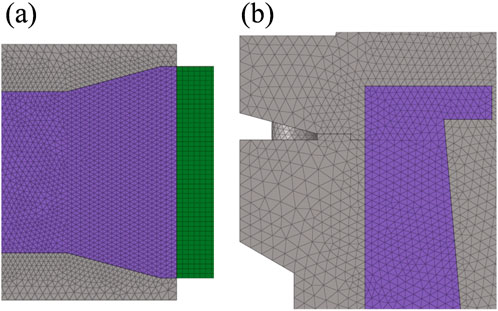
In the meshing, the solid domain and fluid domain (chamber) are all meshed with tetrahedral mesh due to the complex structure. The inlet section and outlet section use hexahedral mesh, and the mesh of the face at the junction of hexahedron and tetrahedron is articulated by grid segmentation. The grid independence test is shown in Figure 5. Comparing the maximum velocity of the flow field under four grid quantities of 0.968 million, 1.88 million, 2.33 million and 2.89 million, it can be found that the calculation result changes very little when the grid quantity increases to 1.88 million or more, so the grid quantity of 1.88 million meets the calculation requirements. The grid details are shown in Figure 6, and the y + value of the grid is 70.
In the structural stress calculation, the flange sealing surface is the key area of concern, so in the independence test of the solid domain mesh, the mesh is divided into different layers along the radial direction on the sealing surface to obtain two different grid quantities (34.7 thousand, 36.2 thousand). A bolt preload of 70% yield limit is applied for static calculations, and the contact pressure at coordinates (175.5, 0, 0) on the sealing surface is extracted and compared, and the results are shown in Table 2. The relative error of the calculated results for the meshes at the two quantities is 2.9%, which indicates that the mesh with the quantity of 34.7 thousand meets the calculation requirements.
2.3 Boundary condition and load setting
In this paper, an operating condition transition that causes leakage of the main gate valve in a marine nuclear power plant is used as the calculation background. Figure 7 shows the variation curves of temperature and pressure in the primary loop system during the process (data normalized), which shows that the temperature does not change in the first 30 s, and the pressure has a small decrease. The temperature drops rapidly from 30 s to 60 s. After 60 s, the temperature is unchanged, and the pressure rises and then fluctuates slightly.
The standard RNG k∼ε turbulence model is used in CFD simulation. The fluid medium is incompressible liquid water. The density change of water in the process is less than 10%, which has little effect on the temperature calculation results, so the density of water is the density value at average temperature, i.e., 771.6 kg/m3. The dynamic viscosity of water is 9.82 × 10⁻⁵ Pa s. The inlet flow velocity is 0.5 m/s, and the inlet temperature is set by the user-defined function (UDF) according to the curve in Figure 7. The outlet is the pressure outlet boundary.
In the structural stress calculation, the valve plate and the valve plate lifting mechanism are ignored because the valve plate does not have any effect on the structural sealing. Y-direction, X-direction and symmetry constraints are set on the valve bottom surface, inlet end surface and symmetry surface, respectively. The valve components are assembled and fixed by contacting each other. The contact thermal resistance is considered in the thermal analysis, and the surface contact thermal resistance in dry metal-to-metal contact is 2.58 × 10⁻⁴°C·m2/W (Schroeder, 2015). The loading conditions contain bolt preload, temperature load, and pressure load.
(1) Bolt preload: Valve deck and valve body are connected by bolts, and the value of the bolt preload directly affects the sealing performance of the main gate valve. According to the Mechanical Design Manual, the upper limit of the bolt preload Fmax (80% of the material yield limit) is calculated by combining the design parameters of the bolt. The bolt preload is loaded according to Fmax, and then gradually iterated to obtain the critical bolt preload that can meet the sealing requirements.
(2) Temperature load conditions: Since the fluid temperature starts to drop rapidly at 30 s and remains essentially constant after 60 s, the initial condition for the thermal analysis is the fluid temperature at 30 s. In order to transfer the temperature to the bolts, the calculation time is increased to 720 s. The temperature distribution obtained from the thermal analysis is transferred to the structural stress calculation as the temperature load.
(3) Pressure load conditions: The valve chamber is under pressure load, which is divided into fluid dynamic pressure and internal pressure. The fluid dynamic pressure is very small compared to the internal pressure as calculated by FLUENT, so only the internal pressure load is considered. The value of the internal pressure load is set according to Figure 7.
2.4 Validation of CFD simulation
To verify the accuracy of the numerical simulation in this paper, the experimental results from Chen et al. (2021) are referred. The experimental setup, sketched in Figure 8, was built to study the eccentric jet-flow characteristics induced by an experimental gate valve in the downstream pipeline. Two regulating valves (inlet and outlet), installed upstream and downstream of the gate valve, were used to regulate the inlet and outlet flow. A pipeline with the length of 10D was installed upstream to ensure full inflow, and a pipeline with the length of 20D was installed downstream. The dimensional parameters of the experimental pipe and gate valve are shown in Figure 9, four lines of pressure monitoring sites were distributed on the Section 2 (downstream pipeline of the gate valve) at top, bottom, left, and right to obtain the local static flow pressures. In addition, fifteen pressure sensors along every pressure monitoring line were used to collect the pressures. To reveal the valve-induced eccentric jet-flow evolution performance in pipeline, the valve openings of 20%, 50%, and 80% were selected.

Figure 8. Schematic of experimental setup (Chen et al., 2021).

Figure 9. The dimensional parameters of the experimental pipe and gate valve (Chen et al., 2021).
The same turbulence model as in this paper is adopted and the same physical model as the experimental pipe and gate valve is established for CFD simulation, and the boundary conditions of the simulation are kept consistent with the parameters in the experiment. Figure 10 shows the average pressure at each monitoring location collected in experiments and corresponding values in simulation under different valve openings, it can be found that the corresponding numerical simulation results are shown agreeing well with the experimental data, which means the numerical simulations are reliable and qualified for subsequent internal flow characteristics analysis.

Figure 10. Average pressures for experiment and simulation along the downstream pipeline under different valve openings. (A) 20% valve opening. (B) 50% valve opening. (C) 80% valve opening.
3 Results and discussion
3.1 Analysis of flow field
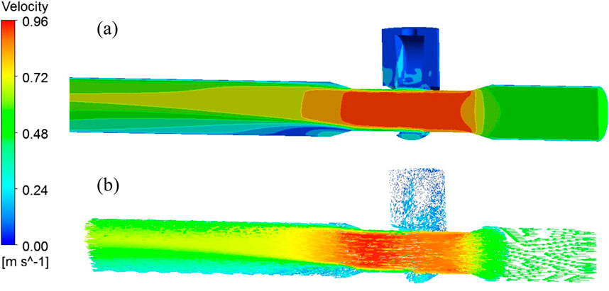
The velocity distribution of the main gate valve flow field is shown in Figure 11. It can be found that there is a significant difference in the velocity distribution in the valve chamber. Due to the blocking effect of the valve plate, the streamlines in the upper part of the valve chamber are sparse and the flow velocity is low. The streamlines in the straight-through part of the valve chamber are dense and the flow velocity is large.
The temperature distribution of the inner wall of main gate valve is shown in Figure 12. It can be found that the flow velocity of the fluid in the upper part of the valve chamber is relatively slow, which affects its heat transfer capacity. When the fluid temperature in the straight-through part of the valve chamber decreases rapidly, the temperature change in the upper part of the valve chamber lags behind, and the upper wall of the valve chamber maintains a high temperature at 60 s. The temperature distribution in the upper part of the valve chamber gradually tends to be uniform at 360 s, and the temperature gradient is small enough at 720 s.
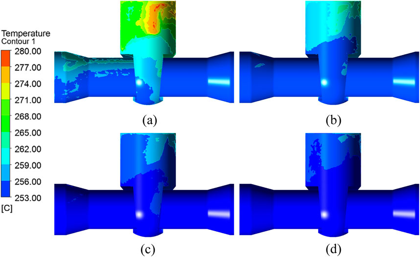
Figure 12. Wall temperature distribution of main gate valve at different times. (A) 60 s. (B) 180 s. (C) 360 s. (D) 720 s.
3.2 Analysis of structural temperature
Figure 13 shows the structural temperature distribution of the main gate valve. The overall temperature of the valve is the same as the fluid at 0 s (i.e., the 30th s during the operating condition transition). In 0∼30 s, the fluid temperature decreases, and the valve body temperature first starts from the inlet and outlet, and gradually decreases toward the sealing surface and the bolts. After 30 s, the fluid temperature gradually stabilizes, and there is no obvious temperature gradient near the sealing surface and the bolts. There is already an obvious temperature gradient near the sealing surface at 300 s, and the temperature has been transferred to the bolts at 720 s. The above calculation results show that the temperature change of the solid structure significantly lags behind the fluid. Although the fluid temperature drops the fastest from 0 s to 30 s, the temperatures of sealing surface and bolts do not change significantly during this time period, and last until 720 s before affecting the temperatures of sealing surface and bolts.
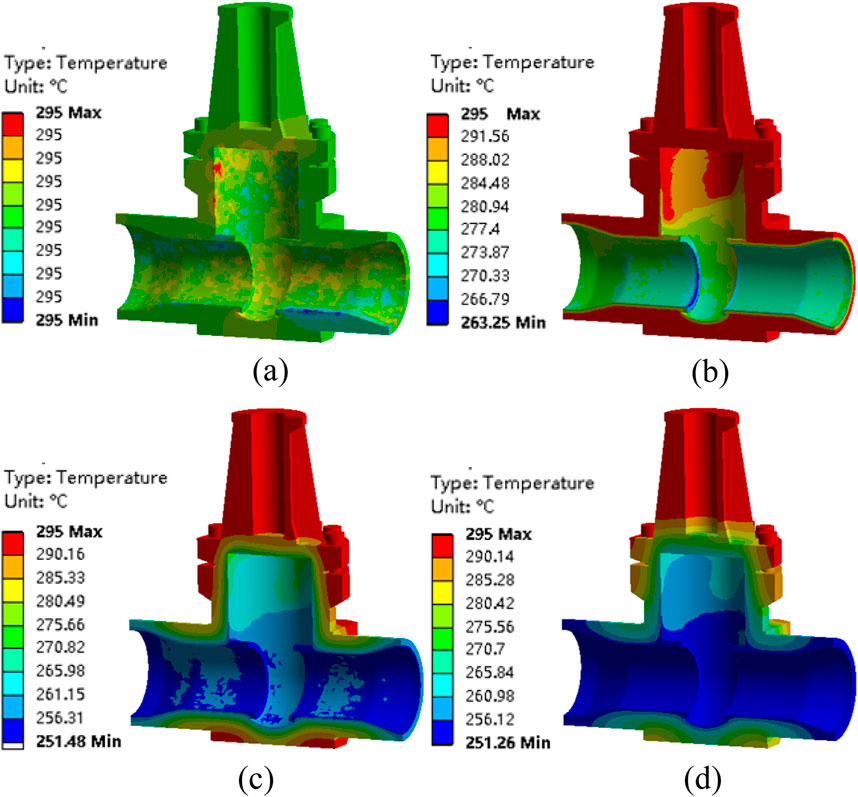
Figure 13. Structure field temperature distribution of main gate walve. (A) 0 s. (B) 30 s. (C) 300 s. (D) 720 s.
3.3 Analysis of the contact pressure
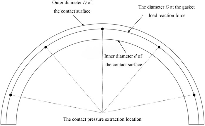
This main gate valve is a rigid plane sealing structure, and the sealing performance is evaluated by the method (Li, 1993) that no leakage occurs if the contact pressure on the sealing surface is greater than the minimum design compressive stress y (180 MPa). In order to extract a reasonable contact pressure, the diameter G at the gasket load reaction force is used as the extraction location of the contact pressure, as shown in Figure 14. Five points on the semicircle are selected and the smallest of these contact pressures is taken as the evaluation criterion.
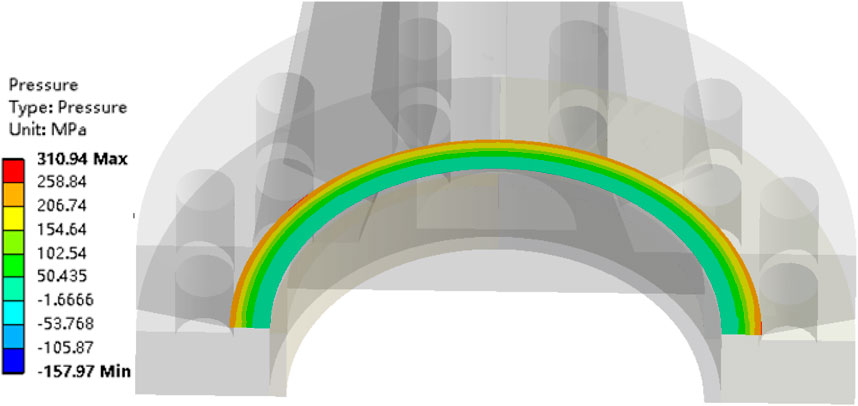
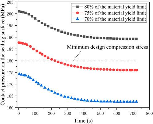
The contact pressure distribution on the sealing surface when the bolt preload is 70% of the material yield limit is shown in Figure 15, which shows that the contact pressure increases from inside to outside along the sealing surface. The variation of the sealing surface contact pressure under the three bolt preloads (80%, 75% and 70% of the material yield limit) is shown in Figure 16. It can be found that the rapid drop in fluid temperature leads to a large temperature gradient in the valve structure, which in turn causes uneven local stress distribution as well as uncoordinated deformation in the sealing structure, and eventually causes a drop in the sealing surface contact pressure. In the first 30 s when the temperature drops fastest, the contact pressure does not drop significantly. The contact pressure drops faster from 50 s to 350 s, which is consistent with the change law of temperature transfer in the solid structure.
According to the assessment method of the sealing performance of the main gate valve, it can be found that when the bolt preload is 75% and 70% of the material yield limit, there are leaks. Only when the bolt preload reaches the upper limit (80% of the material yield limit), it can ensure that the valve does not leak during the operating condition transition. In the actual situation, the bolt preload is difficult to reach the upper limit, and the main gate valve is bound to leak under this condition, which also proves that the result of the numerical simulation is in good agreement with the actual situation.
The above calculation results show that the rapid drop of fluid temperature inside the main gate valve causes leakage. Therefore, in order to study the effect of temperature drop rate on the sealing performance of the main gate valve, two other operating conditions with different temperature drop rates (1°C/s, 2°C/s) are calculated. The calculation results of the sealing performance for the temperature drop rates of 1°C/s and 2°C/s are shown in Figure 17. It can be found that as the temperature drop rate increases, the contact pressure on the sealing surface decreases faster. At the temperature drop rate of 2°C/s, even if the bolt preload reaches the upper limit, the contact pressure is still lower than the minimum design compression stress, the main gate valve is bound to leak.
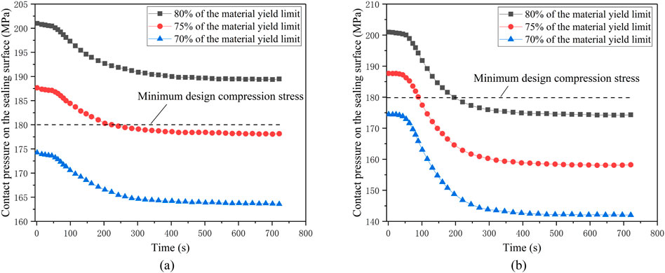
Figure 17. Variation of contact pressures on the sealing surface at different temperature drop rates. (A) Temperature drop rate of 1°C/s. (B) Temperature drop rate of 2°C/s.
4 Conclusion
In this paper, based on the fluid-solid-thermal multi-physical field coupling method, the flow heat transfer characteristics and sealing performance of the main gate valve of a marine nuclear power plant are numerically simulated, and the effects of the rapid drop of coolant temperature and the drop rate on the sealing performance of the main gate valve during an operating condition transition are studied. The main conclusions are as follows:
(1) During the rapid temperature drop of the inlet coolant of the main gate valve, the fluid flow rate in the upper part of the valve chamber is slow and the heat transfer capacity is poor, resulting in the temperature variation of the sealing structure lagging significantly behind the temperature variation of the fluid, and a significant temperature gradient appears at the flange sealing surface, forming a thermal shock effect.
(2) The contact pressure on the sealing surface of the valve flange increases from the inside to the outside. During the operating condition transition, the unevenness of stress and deformation caused by thermal shock leads to a decrease in contact pressure on the sealing surface. Under three bolt preloads (80%, 75% and 70% of the material yield limit), the valve does not leak only when the bolt preload reaches the upper limit (80% of the material yield limit).
(3) The rate of coolant temperature drop has a significant impact on the sealing performance of the main gate valve during the operating condition transition. The faster the rate of coolant temperature drop, the more severe the leakage.
Data availability statement
The original contributions presented in the study are included in the article/supplementary material, further inquiries can be directed to the corresponding author.
Author contributions
CY: Writing–review and editing. YH: Writing–original draft. FS: Writing–review and editing. LA: Supervision, Validation, Writing–review and editing.
Funding
The author(s) declare that no financial support was received for the research, authorship, and/or publication of this article.
Conflict of interest
The authors declare that the research was conducted in the absence of any commercial or financial relationships that could be construed as a potential conflict of interest.
Publisher’s note
All claims expressed in this article are solely those of the authors and do not necessarily represent those of their affiliated organizations, or those of the publisher, the editors and the reviewers. Any product that may be evaluated in this article, or claim that may be made by its manufacturer, is not guaranteed or endorsed by the publisher.
References
Bazsó, C., and Hős, C. J. (2013). An experimental study on thestability of a direct spring loaded poppet relief valve. J. Fluids and Struct. 42 (42), 456–465. doi:10.1016/j.jfluidstructs.2013.08.008
Chen, C., Wu, G., Fu, X., Tang, B., Zhen, H., Li, P., et al. (2018). Design optimization of thermal shock resistance double -cone seal structure of pressurizer. Nucl. Power Eng. 39 (4), 177–181. doi:10.13832/j.jnpe.2018.04.0176
Chen, D., Wang, Y., Liu, Q., Lin, Z., Zhu, Z. c., and Mao, W. (2021). Study on the eccentric jet-flow characteristics induced by the opening regulation with a gate valve. Proc. Institution Mech. Eng. Part C J. Mech. Eng. Sci. 235 (21), 5353–5364. doi:10.1177/0954406221994889
Dai, X., Huang, Z., Wu, X., Zhao, H., and Shi, H. (2021). Fluid-solid-thermal coupling analysis of rock failure under the joint action of cutting and jet impingement. Geothermics 94, 102092. doi:10.1016/j.geothermics.2021.102092
He, X., Zhang, C., and Tian, D. (2019). Strength analysis and structure optimization of gate valve body based on finite element software. EDP Sci. 136, 03019. doi:10.1051/e3sconf/201913603019
Hu, B., Zhu, H., Ding, K., Zhang, Y., and Yin, B. (2016). Numerical investigation of conjugate heat transfer of an underwater gate valve assembly. Appl. Ocean Res. 56, 1–11. doi:10.1016/j.apor.2015.12.006
Hwang, I. S., Park, S. J., Oh, W., and Lee, Y. L. (2017). Linear com-pressor discharge valve behavior using a rigid body valve model and a fsi valve model. Int. J. Refrig. 82, 509–519. doi:10.1016/j.ijrefrig.2017.05.034
Li, Y. (1993). Determination of pre-tightening force and pre-tightening torque of high strength bolts. Mechanism 20 (2), 20–23.
Lin, Z., Ma, G., Cui, B., Li, Y., Zhu, Z., and Tong, N. (2022). Influence of flashboard location on flow resistance properties and internal features of gate valve under the variable condition. J. Nat. Gas Sci. Eng. 33, 108–117. doi:10.1016/j.jngse.2016.05.025
Liu, P., Liu, Y., Huang, Z., Cai, B., Sun, Q., Wei, X., et al. (2019). Design optimization for subsea gate valve based on combined analyses of fluid characteristics and sensitivity. J. Petroleum Sci. Eng. 182, 106277. doi:10.1016/j.petrol.2019.106277
Ma, B., Lu, D., Du, Y., Cao, Q., Si, Y., Wang, C., et al. (2022). Numerical study on thermal shock of central measuring shroud with fluid–solid thermal coupling in the “Monju” reactor. Nucl. Eng. Des. 390, 111712. doi:10.1016/j.nucengdes.2022.111712
Marek, A., and Okrajni, J. (2013). Local stress-strain behavior of a high-temperature steam valve under transient mechanical and thermal loading. J. Mater. Eng. Perform. 23 (1), 31–38. doi:10.1007/s11665-013-0744-3
Schroeder, C. J. (2015). Metallurgical failure analysis ofa fractured steam control valve stem. J. Fail. Analysis Prev. 15 (3), 370–378. doi:10.1007/s11668-015-9957-0
Tang, J., Xie, W., Wang, X., and Chen, C. (2022). Simulation and analysis of fluid–solid–thermal unidirectional coupling of near-space airship. Aerospace 9 (8), 439. doi:10.3390/aerospace9080439
Wang, K., Xie, K., Zhang, H., Qiang, Y., Du, Y., Xiong, Y., et al. (2022). Numerical evaluation of the coupled/uncoupled effectiveness of a fluid-solid-thermal multi-field model for a long-distance energy transmission pipeline. Energy 251, 123964. doi:10.1016/j.energy.2022.123964
Yu, H., Zhao, X., Fu, S., and Zhu, K. (2022). Analysis of the fluid-solid-thermal coupling of a pressurizer surge line under ocean conditions. Nucl. Eng. Technol. 54, 3732–3744. doi:10.1016/j.net.2022.05.026
Keywords: marine nuclear power plant, main gate valve, fluid-solid-thermal coupling, sealing performance, CFD
Citation: Yuqing C, Hang Y, Shengwei F and Ang L (2024) Study on sealing performance of main gate valve of marine nuclear power plant based on fluid-solid-thermal coupling method. Front. Energy Res. 12:1375806. doi: 10.3389/fenrg.2024.1375806
Received: 24 January 2024; Accepted: 14 November 2024;
Published: 29 November 2024.
Edited by:
Longxiang Zhu, Chongqing University, ChinaCopyright © 2024 Yuqing, Hang, Shengwei and Ang. This is an open-access article distributed under the terms of the Creative Commons Attribution License (CC BY). The use, distribution or reproduction in other forums is permitted, provided the original author(s) and the copyright owner(s) are credited and that the original publication in this journal is cited, in accordance with accepted academic practice. No use, distribution or reproduction is permitted which does not comply with these terms.
*Correspondence: Yu Hang, ODcwMDIxMjk1QHFxLmNvbQ==
 Chen Yuqing
 Yu Hang*