 Xiaokun Zhang
 Zongyao Qi1
94% of researchers rate our articles as excellent or good
Learn more about the work of our research integrity team to safeguard the quality of each article we publish.
Find out more
ORIGINAL RESEARCH article
Front. Energy Res. , 06 March 2024
Sec. Advanced Clean Fuel Technologies
Volume 12 - 2024 | https://doi.org/10.3389/fenrg.2024.1375108
This article is part of the Research Topic Production Technology for Deep Reservoirs View all 37 articles
In order to improve the oil recovery of mid-deep heavy oil reservoirs, this study investigates the efficiency of enhanced oil recovery and the mechanisms of oil displacement in mid-deep heavy oil reservoirs using different injected gases (N2, CH4, CO2) and development approaches (gas flooding and gas huff-n-puff) through a series of experiments. These experiments include high-pressure physical properties tests of crude oil after gas injection, displacement efficiency tests of gas injection, and displacement efficiency tests of gas huff-n-puff. The results indicate that for mid-deep heavy oil reservoirs, the preferred optimal injection gas is CO2, with gas huff-n-puff being the most effective development method. Furthermore, a numerical simulation study was conducted to explore the adaptability parameters of CO2 huff-n-puff development in different well patterns, encompassing variables such as the amount of gas injected per cycle, crude oil viscosity, reservoir permeability, and oil layer thickness.
Currently, China’s onshore heavy oil resources are abundant, with estimated resources of approximately 198 × 10⁸ tons and proven reserves of about 40 × 10⁸ tons (Yuan and Wang, 2018; Guan et al., 2023). However, the average recovery rate of these heavy oil reservoirs is less than 20%, indicating a vast potential for exploitation. Due to the high content of asphaltenes and resins, heavy oil is characterized by high viscosity and poor flow properties (Alcazar-Vara et al., 2012; Dong et al., 2013; Varfolomeev et al., 2022), making it difficult to develop effectively using conventional methods such as water flooding.
At present, the development of heavy oil reservoirs mainly focuses on thermal recovery methods such as steam huff-n-puff (Shen et al., 2005; Wan et al., 2020; Sun et al., 2022), steam flooding (Prats, 1992; Gael et al., 1995; Sutadiwiria and Azwar, 2011; Carpenter, 2018), Steam Assisted Gravity Drainage (SAGD) (Wu et al., 2013; Zhou and Zeng, 2014; Velayati and Nouri, 2020), and fire flooding (Xi et al., 2013; Guan et al., 2017a). These methods are predominantly utilized in developing shallow to mid-depth heavy oil reservoirs. The essence of these technologies lies in using heat to reduce the viscosity of heavy oil, thereby improving its flow properties. Particularly, steam huff-n-puff, and steam flooding involve injecting high-temperature steam into the reservoir, transferring heat to the heavy oil and effectively reducing its viscosity (Gao et al., 2019; Li et al., 2020). The SAGD technique creates a steam chamber in the reservoir through horizontal wells, leveraging gravity and heat transfer to facilitate oil flow to the production wells. Fire flooding, on the other hand, involves burning a portion of the in-situ crude oil to generate heat, thus lowering the viscosity of the surrounding crude oil (Guan et al., 2017b; Li et al., 2018). However, with increasing reservoir depths, these traditional thermal recovery techniques face new challenges. In deeper reservoirs, significant heat loss occurs during steam transmission from the wellhead to the bottom, substantially reducing the thermal efficiency of steam upon reaching the target depth. This reduction in heat results in a decreased radial influence of the steam, thus reducing the effective sweep area of the reservoir and impacting oil recovery rates. The current solutions generally involve the use of injected gases, solvents, urea, and other common media (Wang et al., 2013; Haddad and Gates, 2017; Zhang et al., 2017; Xi et al., 2019; Li et al., 2020; Cui et al., 2020; Wang et al., 2023a; Wang et al., 2023b; Chu and Zhang, 2023; Prasad et al., 2023). Al-Murayri (Al-Murayri et al., 2016) employed the Expanding Solvent Steam Assisted Gravity Drainage (ES-SAGD) method, which utilizes a combination of heat transfer and mass transfer processes to enhance the flow of high-viscosity oil. This approach significantly reduces the water and natural gas requirements for producing and injecting steam. Yuan (Yuan et al., 2017) utilized xylene as a soluble solvent for asphaltenes, conducting numerical simulations to compare the performance during the startup phase with and without solvent injection, both in the preheating stage and the early production period. The results indicated that within the soaking period, the diffusion of the injected solvent improved the sweep area, significantly reducing the viscosity of the oil. This solvent-aided startup process in SAGD shortened the preheating duration and decreased steam consumption.
The phenomenon of foam oil formation (Sarma and Maini, 1992; Claridge and Prats, 1995; Sheng et al., 1995; Zhou et al., 2016) created by injected gases, is particularly significant. It effectively reduces the viscosity of heavy oil, enhancing its flow properties. This technique primarily involves the formation of foam in the oil through the dissolution of gas, thereby increasing oil mobility. Research on foam oil technology focuses on aspects such as the influencing factors of dissolved gas drive, the mechanism of foam oil formation, and micro-scale seepage characteristics (Huerta et al., 1996; Andarcia et al., 2000; Kamp et al., 2001; Bennion et al., 2003; Wang et al., 2012). For instance, studies examine the impact of gas type, pressure, and temperature on the formation and stability of foam oil, as well as its flow behavior in porous media. Zhao (Zhao et al., 2022) employed high-temperature foam to enhance steam oil recovery, injecting both foam and steam into the reservoir to block larger pores and improve the sweep efficiency, thereby reducing the viscosity of the reservoir’s crude oil and ultimately increasing the oil recovery rate. Sun (Sun et al., 2016) utilized Polymer-Enhanced Foam (PEF) for oil displacement as a technique to increase the recovery rate in reservoirs. Experiments conducted in parallel core systems with varying permeabilities showed that PEF oil displacement could effectively enhance recovery in low-permeability cores by altering the injection profile. Liu (Liu et al., 2017) analyzed profile control mechanisms by conducting one-dimensional displacement experiments in tight matrix cores and fractured cores, injecting pure foam liquid, air, and air-foam systems. The results demonstrated that air-foam systems could improve performance post water flooding. It is advisable to switch from water flooding to air-foam systems before the water cut reaches approximately 90%.
However, research on gas injection development for mid-deep heavy oil reservoirs, such as medium selection and optimization of development parameters, remains relatively limited. Currently, enhancing research in these areas is crucial for improving the recovery rates of mid-deep heavy oil reservoirs. For instance, exploring the adaptability and efficiency of different gaseous mediums (like carbon dioxide, nitrogen, and natural gas) under varied geological conditions, as well as optimizing injection parameters (such as injection volume, rate, and cycle) are key to maximizing recovery rates. Through such research, we can provide more in-depth theoretical guidance and technical support for the effective development of mid-deep heavy oil reservoirs, thereby achieving new breakthroughs in heavy oil reservoir development technologies.
This paper focuses on the mid-deep ordinary heavy oil reservoirs in the W region of Xinjiang, with a proven reserve of 4007 × 10⁴ tons, facing challenges like poor efficiency in conventional vertical well development and insufficient reservoir mobilization in horizontal well development, rendering them effectively unmobilized to date. There is an urgent need to demonstrate the adaptability of various extraction methods, such as gas (N2, CO2, etc.) huff-n-puff and gas flooding, to form economically effective development approaches. Therefore, this study conducts high-pressure physical property tests of gas-crude oil injection, efficiency tests of gas flooding oil displacement, and effectiveness tests of gas huff-n-puff development for mid-deep heavy oil, exploring the mechanisms and methods of enhancing oil recovery in gas injection development. Based on experimental results, further numerical simulation research was carried out to discuss the adaptability parameters of CO2 huff-n-puff development in different well patterns, providing technical support for the development of heavy oil reservoirs in mid-deep formation.
Injecting gas into medium and deep thick oil reservoirs to form foam oil is an effective technique for enhancing the fluidity and extraction of heavy oil. This approach involves mixing gas (such as air, carbon dioxide, or natural gas) with heavy oil under the high-temperature and high-pressure conditions found underground, resulting in a foamy oil-gas mixture that improves the oil’s physical properties. The benefits of this method are multifaceted.
The creation of foam significantly lowers the viscosity of heavy oil. The gas bubbles disrupt the oil’s continuity, decreasing its internal friction and overall viscosity. This makes the heavy oil more fluid, facilitating its movement through the reservoir and easing extraction.
Besides aiding in bubble formation, the injected gas provides an extra push, driving the heavy oil towards the production well. This process also enhances the flow properties of both oil and water phases, encouraging heavy oil mobilization while reducing water flow, thereby improving oil recovery efficiency. Gas injection also serves to replenish reservoir energy, maintaining or boosting pressure levels. This is crucial in medium and deep reservoirs, where high pressure improves flow conditions and aids in heavy oil recovery. To further explore the mechanism behind foam oil formation through gas injection and its impact on heavy oil viscosity and mobility, a series of experiments were planned and executed.
In this section, firstly, the basic parameters of the samples of the target layer were tested, and then the comparison experiments of different gas flooding and gas huff-n-puff under different conditions were carried out, so as to compare the preferred injection gases and development methods.
In this section, the basic parameters such as dissolution gas-oil ratio, volume factor, and gas-containing crude oil viscosity of three gases N2, CH4, and CO2 were tested using destination block crude oil.
(1) Experimental materials and device. To meet the requirements for the widespread application of gas injection techniques in mid-deep heavy oil reservoirs in Xinjiang, priority was given to selecting blocks with large reserves, typical reservoir characteristics, deep formation, and high viscosity. Following this principle, the crude oil sample from well W1 was chosen for the experiment. The injection gas were N2, CH4, CO2, and the purity of the experimental gases was 99.999%. The experimental device used was the YRD-70/300 high-pressure physical property analyzer.
(2) Experimental scheme and steps. The experimental temperature was set at 34°C, with pressures at 8MPa, 10MPa, 11MPa, 13MPa, and 15 MPa. Taking the PVT properties test of N2-crude oil at 34°C as an example, the procedure was as follows: First, saturated oil at 15 MPa was prepared for a single degassing experiment and viscosity test. Then the pressure was reduced to 13 MPa, and the gas was released under pressure to obtain saturated oil at the corresponding pressure, followed by another single degassing experiment and viscosity test. This process was repeated at 11MPa, 10MPa, and 8 MPa.
This section conducts a series of experiments to investigate the oil displacement efficiency of different gases, such as N2, CH4, and CO2, under various conditions.
(1) Experimental materials. The experimental oil is heavy oil from well W1, with a viscosity of 256 mPa s at 50°C. The purity of the experimental gases is 99.999%. The experimental core is a 25 mm × 300 mm synthetic core, with specific parameters detailed in Table 1.
(2) Experimental device. The experiment device used a high-pressure one-dimensional proportional physical model, consisting of an injection system, model system, data acquisition system, and production system. The schematic and physical diagram of the experimental device is shown in Figure 1.
(1. Container of water/oil, 2. pump, 3. tank, 4. pressure transducer, 5. six-way valve, 6. mass flowmeter, 7. high-pressure gas cylinder, 8. thermostats, 9. core holder, 10. gas storage tank, 11. hand pump, 12. data collection system, 13. back-pressure valve, 14. collection beaker)
(3) Experimental steps. The experimental steps were as follows:
1) Prepared the core holder model and determined the pore volume of the sand filling tube.
2) Established the physical experimental model according to the experimental flow chart, and pressure tested the system according to the designed experimental pressure. The pressure test lasted for 1 h, and a pressure drop of less than 0.05 MPa was considered acceptable.
3) Connected the core holder to the oil displacement experimental process. Set the outlet back pressure and thermostatic box temperature according to the experimental temperature and pressure, and saturated the core with oil to calculate the original oil saturation of the core.
4) The displacement speed was 0.15 mL/min for gas injection (equivalent to the formation flow rate under formation conditions), based on the similarity criteria. The initial temperature of the model was the reservoir temperature 34°C.
5) Displaced at a constant speed as determined, and recorded time, oil production, liquid production, inlet and outlet pressures, pressure difference, and temperature parameters. Recorded more frequently at the initial stage of water breakthrough. As the oil production decreased, gradually extended the recording intervals. The experiment concluded when the water cut reached above 99.50% and the pressure differential stabilized.
6) Cleaned the residual oil in the core using the distillation dewatering process and measured the produced water and oil quantities.
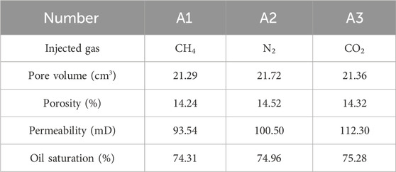
TABLE 1. Parameters related to experimental cores.
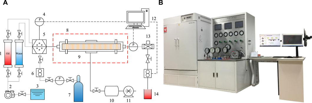
FIGURE 1. High-pressure one-dimensional physical model diagram (A). schematic; (B). physical.
Repeated the above experimental steps to conduct N2, CH4, and CO2 oil displacement experiments sequentially, obtaining the displacement efficiency for different injected gases.
In this section, three cycles of gas huff-n-puff physical simulation experiments using N2, CH4, and CO2 were conducted with crude oil from well W1 to explore the mechanisms of enhanced oil recovery with different injection gases.
The gas huff-n-puff testing experiment utilized the same experimental materials and equipment as shown in Figure 1, with the sand-filled tube model having dimensions of 25 mm × 500 mm. The specific parameters of the core are detailed in Table 2.
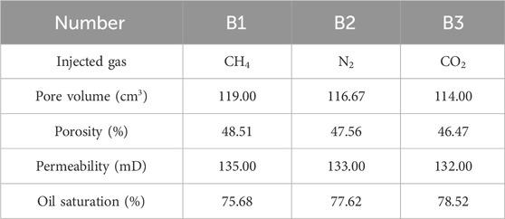
TABLE 2. Parameters related to experimental cores.
The specific experimental steps are as follows:
1) Prepared the core holder model and measured the pore volume of the sand-filled tube.
2) Set up the experimental process according to the flow chart and pressure tested the system until it meets the required standards.
3) Connected the model to the experimental process. Set up the experiment according to the temperature and pressure conditions, and injected the experimental oil into the core at a constant low speed to saturate it, thus obtaining the original oil saturation of the core.
4) Apply the similarity criteria for conversion. In this experiment, the gas injection pressure was set at 15 MPa with a soak time of 24 h. The initial temperature of the model was set to the reservoir temperature of 34°C.
5) After a soak time of 24 h, proceeded with the determined pressure drop and vented, while recording time, oil production, liquid production, gas production, inlet and outlet pressures, and temperature parameters. The experiment concluded when the pressure dropped to 5 MPa and the pressure differential stabilized.
6) Cleaned the residual oil from the core using the distillation dewatering process to determine the oil production.
Repeated the above experimental steps to conduct N2, CH4, and CO2 oil displacement experiments, obtaining the displacement efficiency for different injected gases.
Through the experiment, the solubility, gas-containing crude oil viscosity, and volume factor of W1 well crude oil at 34°C under different pressure conditions with injected N2, CH4, and CO2 were measured. The experimental results are displayed in Figure 2.
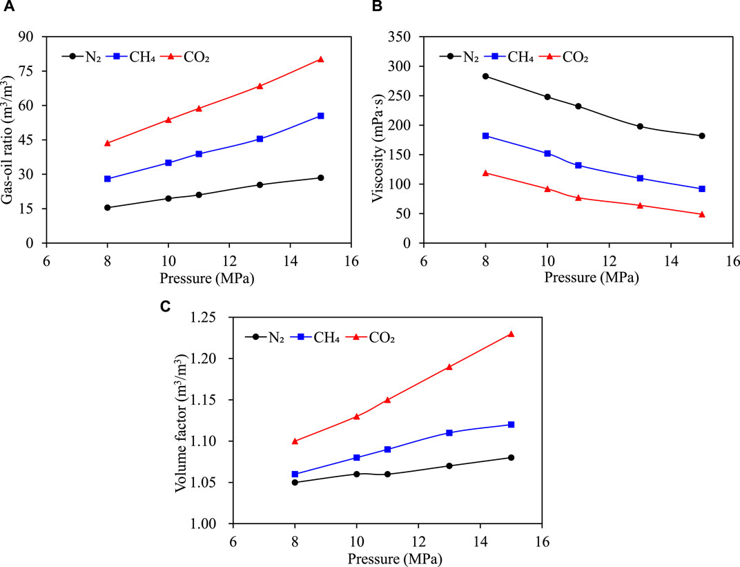
FIGURE 2. Plot of high-pressure physical parameters of crude oil versus pressure for different gas injections (A) solubility (B) viscosity of gas-containing crude oil; (C) crude oil volume factor.
As shown in Figure 2A, under the condition of 34°C, the solubility of N2, CH4, and CO2 gases in crude oil increases with the rise in saturation pressure. Among them, at the same pressure, the solubility of CO2 is the highest, and that of N2 is the lowest. Specifically, at a pressure of 15MPa, the solubility of CO2 is 80.19 m³/m³, with a solubility coefficient of 5.346 (m³/m³)/MPa.
From Figure 2B, it is observed that at 34°C, the viscosity of crude oil dissolving N2, CH4, and CO2 decreases with increasing saturation pressure. At the same pressure, the viscosity of crude oil with injected N2 is the highest, while the crude oil with injected CO2 has the lowest viscosity. At a pressure of 15MPa, the viscosity of crude oil with injected CO2 is 49 mPa s, resulting in a viscosity reduction rate of 93.2%, and the CO2 has the best viscosity-reducing effect.
As shown in Figure 2C, at 34°C, the crude oil volume factor for oil dissolving N2, CH4, and CO2 increases with the rise in saturation pressure. Under the same pressure conditions, the volume factor of crude oil dissolving CO2 is the highest, while that of N2 is the lowest. Specifically, at a pressure of 15MPa, the volume factor for CO2 is 1.23 m³/m³, with a shrinkage rate of 18.70%.
Through our experiments, we’ve made important discoveries regarding gas solubility, changes in crude oil viscosity, and the crude oil volume coefficient. The key findings of this study include:
The solubility of N2, CH4, and CO2 in crude oil increased with rising saturation pressure. Notably, CO2 exhibited the highest solubility among the three gases, underlining its superior potential for enhancing crude oil recovery in reservoirs. This is attributed to CO2’s remarkable solubility coefficient of 5.346 (m³/m³)/MPa. At a pressure of 15 MPa, CO2 achieved a solubility of 80.19 m³/m³, highlighting its effectiveness. The dissolution of these gases into crude oil led to a decrease in oil viscosity with increasing saturation pressure, a critical factor for boosting crude oil flowability and recovery efficiency. The marked viscosity reduction observed following CO2 injection, with a rate of 93.2%, underscores the efficacy of CO2 injection in enhancing the mobility of heavy oils. The crude oil volume coefficients after gas dissolution also rose with pressure. The increase was most pronounced for CO2, suggesting that CO2 not only improves the flow characteristics of crude oil within the reservoir but also significantly enhances the reservoir’s displacement efficiency.
This study highlights the distinct advantages of CO2 injection in improving crude oil recovery by demonstrating its superior solubility, its ability to reduce crude oil viscosity effectively, and its impact on increasing the crude oil volume coefficient. These findings underscore the potential of CO2 injection as a valuable technology for enhancing the recovery and mobility of crude oil, particularly in challenging reservoir conditions.
Using crude oil from well W1, physical simulation experiments of oil displacement under simulated reservoir conditions were conducted with injected N2, CH4, and CO2. The results are shown in Figure 3.
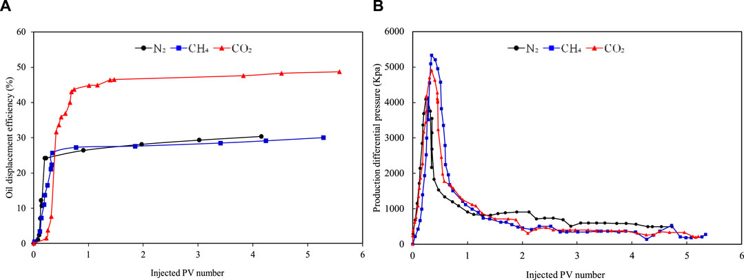
FIGURE 3. Results of N2, CH4, and CO2 injection oil flooding experiments (A) Curve of oil flooding efficiency versus injected PV number for different injection gas; (B) Curve of production differential pressure versus injected PV number for different injection gas.
As indicated in Figure 3A, under the same injection volume conditions, CO2 injection achieved the highest oil displacement efficiency at 48.35%, followed by N2 at 30.18%, and CH4 at 30.07%. Figure 3B reveals that with the increase in the number of injected pore volumes (PV), the production pressure differential gradually increases. The peak production pressure differential in CH4 injection is the highest, followed by CO2, with N2 being the lowest. Furthermore, the peak of the production pressure differential for CH4 injection occurred the latest, indicating that the breakthrough timing of oil displacement by CH4 injection is later than that of CO2 and N2 injections.
Analysis suggests that during the displacement processes with injected N2, CH4, and CO2, due to the stronger solubility of CH4 and CO2 in crude oil under the same injection pressure compared to N2, the gas breakthrough occurs earliest in N2 injection, reaching the peak production pressure differential first. The partial dissolution of CH4 and CO2 gases results in the expansion of crude oil volume and a decrease in heavy oil viscosity, enhancing the fluidity of the crude oil. However, under experimental conditions, miscible flooding was not achieved after gas injection, and the flow rate is relatively high, which leads to gas breakthrough and consequently lower oil displacement efficiency.
Our experiments provided a thorough insight into how different gas injections—specifically N2, CH4, and CO2—affect oil drive efficiency and production differential pressure. The findings highlight CO2’s significant impact, enhancing oil driving efficiency to 48.35%, a substantial improvement over the 30.18% and 30.07% seen with N2 and CH4, respectively. This underscores CO2’s critical role in bolstering oilfield recovery.
Furthermore, the observed trends in production differential pressure shed light on the distinct dynamics of gas-driven oil displacement. CH4 injection, in particular, resulted in the highest and most delayed peak in production differential pressure, indicative of the prolonged crude oil breakthrough in the CH4 displacement process. This variation largely stems from the gases’ solubility in crude oil and their influence on oil flowability. The superior solubility of CO2 and CH4 in crude oil, relative to N2, leads to both an expansion in crude oil volume and a decrease in the viscosity of thick oil, thereby enhancing crude oil flowability. However, this also suggests a potential limitation in further optimizing oil drive efficiency.
Physical simulation experiments of gas huff-n-puff with N2, CH4, and CO2 were conducted on W1 well crude oil, spanning three cycles, to explore the enhanced oil recovery effects and mechanisms of different media in different cycles. The experimental results are shown in Figure 4.
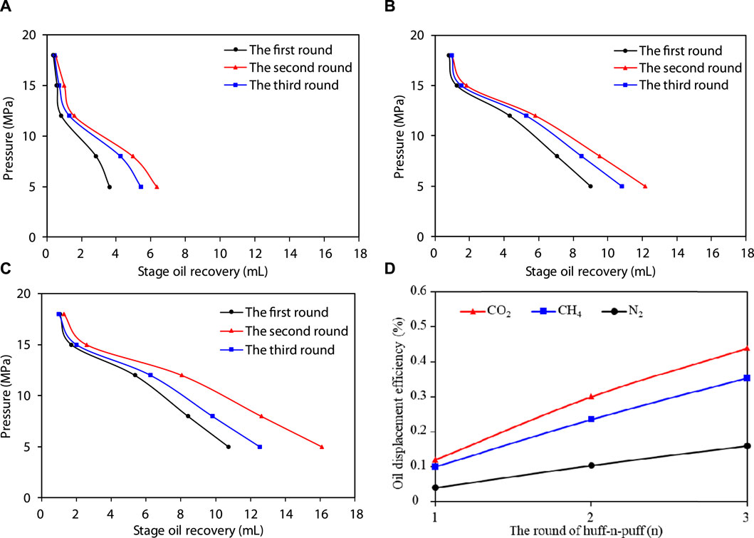
FIGURE 4. Stage oil recovery versus production pressure for three rounds of gas huff-n-puff with different injection gases (A) N2 (B) CH4 (C) CO2 (D) Oil displacement efficiency of different gas.
From the comparison of the three rounds of huff-n-puff results in Figure 4, it is evident that under the same injection volume conditions, CO2 huff-n-puff yields a significantly higher oil recovery than CH4 and N2 huff-n-puff, indicating that the utilization rate of CO2 huff-n-puff is greater than that of CH4 and N2. Due to the strongest solubility of CO2, followed by CH4, and the lowest for N2, the N2 huff-n-puff produces a larger volume of free gas and a longer initial gas production phase, contributing less to oil production. In contrast, the other two gases with higher solubility can form foam oil more effectively, aiding in gas dissolution and crude oil viscosity reduction, ultimately leading to better oil displacement results.
Referencing Figure 4D, after three rounds of injection, CO2 injection yields the highest recovery rate at 44%, outpacing CH4’s 35.5%, and significantly exceeding N2’s modest 16%. This outcome, when juxtaposed with the data from Figure 3, reveals that repeated CO2 injections result in a higher recovery rate than singular CO2 drives. The latter approach, characterized by non-mixed-phase gas drive, tends to precipitate abrupt gas breakthroughs rather than facilitating a steady, uniform displacement of crude oil within the formation, thereby capping the potential for recovery rate enhancements.
Conversely, CO2 injection as a repeated process allows for continuous reintroduction of CO2 into the reservoir, ensuring thorough contact and integration with the heavy oil to create a foam oil. This strategy effectively circumvents the rapid gas breakthrough issue, enabling a more complete mixture of CO2 with the oil and promoting a uniform CO2 distribution throughout the reservoir. Such distribution enhances CO2’s solubility in the heavy oil, broadly lowering the oil’s viscosity across the reservoir and thus improving oil mobility. Consequently, this method more effectively decreases the viscosity of the heavy oil and enhances its flow properties, leading to improved recovery rates.
Our experiments extensively examined the effects and mechanisms of different gases (CO2, CH4, and N2) on enhancing oil recovery across three consecutive injection cycles. The data unequivocally demonstrate that CO2 injection outperforms CH4 and N2 in terms of recovery efficiency under identical conditions. This superiority is primarily due to CO2’s exceptional solubility in crude oil, which not only significantly reduces the oil’s viscosity but also facilitates the formation of foam oil, thereby improving oil displacement efficiency and lowering residual oil saturation.
N2, with its minimal solubility, tends to produce a larger volume of free gas during injection, extending the initial phase of gas production and offering limited benefits to oil recovery enhancement. On the other hand, the greater solubility of CH4 and CO2 aids in foam oil formation, which, coupled with their ability to dissolve in crude oil and reduce its viscosity, substantially enhances the oil displacement effect. CO2, in particular, stands out due to its superior solubility and capacity to decrease viscosity, effectively minimizing residual oil in the reservoir and significantly increasing crude oil recovery rates.
Gas injection to create foam oil not only substantially reduces the viscosity of heavy oil but also enhances its recoverability and recovery rate, making it an especially effective enhancement technique for medium and deep heavy oil reservoirs. However, the application of this method demands precise geological evaluation and engineering design to ensure the effective distribution of gas within the reservoir, taking into account factors such as the choice of gas, injection methods, and reservoir conditions. Utilizing numerical simulation to study the mechanisms by which foam oil improves the recovery rate of heavy oil is both efficient and accurate. Through numerical simulation, the effects of various parameters on the mobility and recovery rate of heavy oil can be explored in detail, providing insights into optimizing this production enhancement technique.
Based on the results of the physical simulation experiments, CO2 was selected as the best injection gas and CO2 huff-n-puff as the best production method. To better understand the adaptability and displacement mechanism of CO2 huff-n-puff in the W block, a three-dimensional numerical simulation model was established using the CMG software STARS module, integrating the geological conditions and crude oil properties of the W1 well area.
Injecting CO2 into medium and deep thick oil reservoirs is a highly effective method for enhancing oil mobility and recovery rates. This technique works by significantly reducing the viscosity of crude oil and increasing the oil-water relative permeability, thereby improving oil flowability. The formation of foam oil through CO2 injection is particularly beneficial in reservoirs where the crude oil has high viscosity, as it markedly enhances oil mobility and consequently boosts recovery rates.
However, the success of CO2 injection depends on several critical parameters, including the volume of gas injected, the viscosity of the crude oil, the permeability of the reservoir, and the thickness of the reservoir. Optimizing these parameters is essential for achieving the most effective development outcomes in practical applications.
The model was established based on the basic geological reservoir parameters and well network parameters of the W1 well area. Two single-well groups were established: ① one with a vertical well for depletion production, ② one with a CO2 huff-n-puff well group consisting of an injection well and a production well. In the CO2 huff-n-puff well, it serves as an injection well during CO2 injection and as a production well after the injection and soaking phases. In the vertical well CO2 huff-n-puff simulation, each huff-n-puff round consisted of 15 days of gas injection, 10 days of soaking, followed by production with a fixed gas output after the soaking period. Each round had a production duration of 600 days, with a total of 4 rounds simulated over 2500 days. Specific parameters are detailed in Table 3. The objective layer is distributed with two interlayers, the thickness is 7 m and 1 m respectively, the permeability and oil saturation of the compartments were set to 0.01, and the permeability field is shown in Figure 5. The specific parameters of the reservoir in the target block are outlined in Table 3. In this table, the viscosity of the crude oil refers to the viscosity of degassed crude oil at 50°C. The subsurface condition is described as a single oil phase, and methane is noted as the dissolved gas within the parameters presented in Table 3.
(1) Single round CO2 injection volume
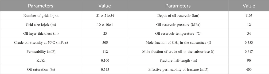
TABLE 3. Parameters related to vertical well model.
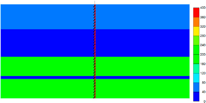
FIGURE 5. Permeability field diagram (JK).
In order to study the influence of single round injection volume on the effect of CO2 huff-n-puff development, 100t, 200t, 400t, 600t, 800t and 1000t were simulated respectively, and the simulation results of CO2 oil exchange rate and profit with different injection volumes are shown in Figure 6.
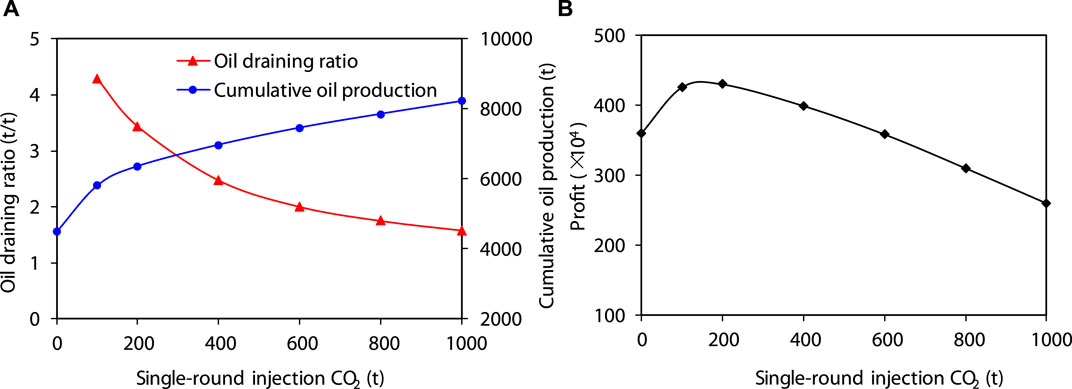
FIGURE 6. Optimization and adaptability study of CO2 huff-n-puff injection volume (A) Single-round CO2 injection volume vs. oil draining ratio and cumulative oil production; (B) Single-round CO2 injection volume vs. profit.
Numerical simulation results indicate that as the CO2 injection volume increases, cumulative oil production gradually increases while the oil draining ratio decreases. At an oil price of $45, profits increase with the injection volume. The maximum profit growth rate is achieved at a single round injection volume of 200 tons of CO2. Beyond 200 tons, the profit gradually decreases. The optimal injection volume is identified as 200 tons per well per round.
(2) Oil viscosity
To study the impact of crude oil viscosity on the effectiveness of CO2 huff-n-puff, simulations were conducted at viscosities of 100 mPa s, 300 mPa s, 500 mPa s, 700 mPa s, and 900 mPa s. Results are shown in Figure 7. It is observed that as the viscosity of the crude oil increases, the cumulative oil production decreases and the total profit reduces, dropping to zero when the viscosity exceeds 500 mPa s. Therefore, it is recommended that vertical well CO2 huff-n-puff is suitable for reservoirs with crude oil viscosity less than 500 mPa s.
(3) Reservoir permeability
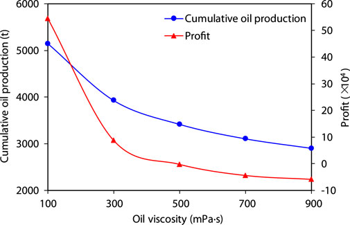
FIGURE 7. CO2 huff-n-puff profit and cumulative oil production -viscosity relationship.
To investigate the influence of formation permeability on CO2 huff-n-puff development, simulations were carried out at permeabilities of 40 mD, 70 mD, 100 mD, 130 mD, and 160 mD.
The results, as shown in Figure 8, demonstrate that cumulative oil production and total profit increase with rising permeability. When permeability exceeds 100 mD, the total profit becomes positive, indicating that vertical well CO2 huff-n-puff is suitable for reservoirs with permeability greater than 100 mD.
(4) Reservoir thickness
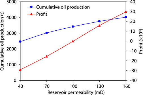
FIGURE 8. CO2 huff-n-puff profit-permeability relationship for straight wells.
To assess the impact of reservoir thickness on CO2 huff-n-puff development, simulations were performed at thicknesses of 6m, 8m, 10m, 12m, and 14 m. The results, depicted in Figure 9, show that as reservoir thickness increases, controlled reserves per well increase, leading to increased cumulative oil production and total profit. The profit turns positive when reservoir thickness exceeds 10m, suggesting that vertical well CO2 huff-n-puff is suitable for reservoirs with a thickness greater than 10 m.
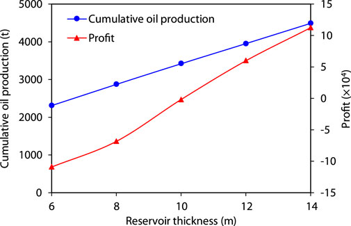
FIGURE 9. CO2 huff-n-puff profit-reservoir thickness relationship for straight wells.
Two single-well group models for horizontal wells were established, one for depletion production and the other for CO2 huff-n-puff, each with one injection well and one production well. The horizontal wells are located in the middle of the oil layer. The number of grids in the i×j×k direction is 21 × 21×34, and grid size in the i×j×k direction is 10 × 10 × 1 m. The other parameters and production regime for horizontal well CO2 huff-n-puff are the same as for vertical wells.
(1) Single cycle CO2 injection volume
Numerical simulation results (Figure 10) reveal that as the CO2 injection volume increases, cumulative oil production increases, but the rate of increase in profit decreases. The maximum profit growth rate is achieved at a single cycle injection volume of 1000–1200 tons of CO2.
(2) Crude oil viscosity
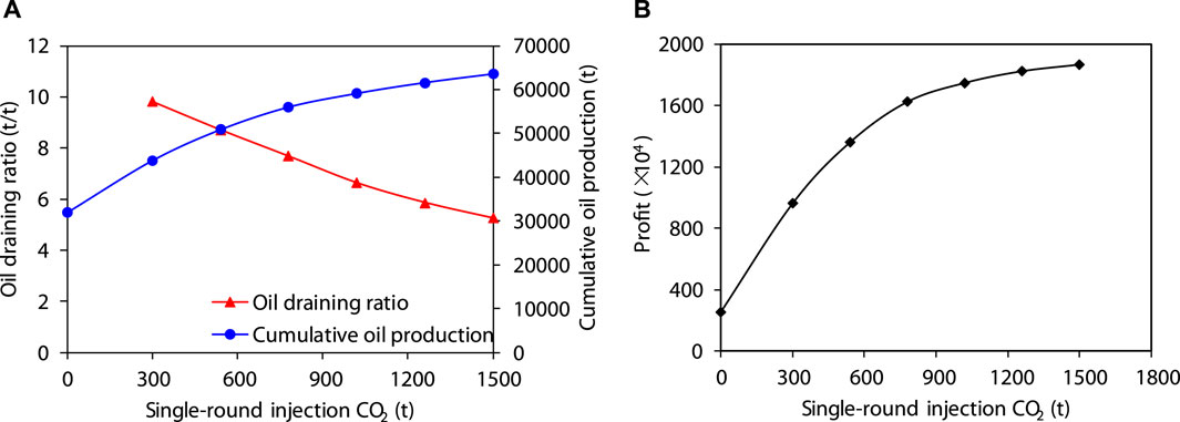
FIGURE 10. Optimization and adaptability study of CO2 huff-n-puff injection volume. (A) Single-round CO2 injection volume vs. oil draining ratio and cumulative oil production; (B) Single-round CO2 injection volume vs. profit.
Simulations at viscosities of 100 mPa s, 300 mPa s, 500 mPa s, 700 mPa s, and 900 mPa s were conducted to study the effect of viscosity on horizontal well CO2 huff-n-puff. The results (Figure 11) show a continuous decrease in cumulative oil production and total profit as viscosity increases, although the total profit remains positive. It is suggested that horizontal well CO2 huff-n-puff is suitable for reservoirs with a viscosity less than 1000 mPa s.
(3) Reservoir permeability
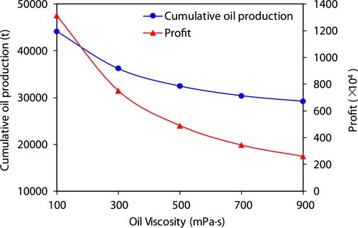
FIGURE 11. CO2 huff-n-puff profit-crude oil viscosity relationship for horizontal wells.
Simulations at permeabilities of 10 mD, 40 mD, 70 mD, 100 mD, and 130 mD were performed to evaluate the impact on CO2 huff-n-puff. The results (shown in Figure 12) indicate that as permeability increases, cumulative oil production and total profit also increase. Profits become positive when permeability exceeds 30 mD, suggesting suitability for reservoirs with permeability greater than 50 mD.
(4) Reservoir thickness
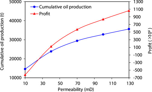
FIGURE 12. CO2 huff-n-puff profit-permeability relationship for horizontal wells.
Simulations at thicknesses of 2m, 4m, 6m, 8m, 10 m were carried out to assess the impact on CO2 huff-n-puff. The results (Figure 13) demonstrate that as reservoir thickness increases, controlled reserves per well increase, leading to increased cumulative.
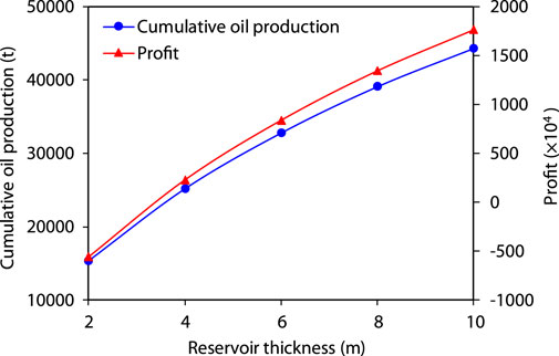
FIGURE 13. CO2 huff-n-puff profit-reservoir thickness relationship for horizontal wells.
The mechanism of foam oil formation through gas injection is pivotal for enhancing crude oil mobility and improving oil-gas contact efficiency. During the CO2 huff-n-puff process, CO2 mixes with heavy oil to form low-viscosity foam oil, which reduces the flow resistance of the oil and increases the oil recovery rate. In our in-depth numerical simulation study of the CO2 huff-n-puff technique’s application in enhancing oilfield production, we identified injection volume, crude oil viscosity, reservoir permeability, and formation thickness as key parameters affecting the technique’s economic benefits and development outcomes. When considering the CO2 huff-n-puff technique, it is crucial to take into account factors such as the reservoir’s crude oil viscosity, permeability, and formation thickness to devise the optimal development plan. These conditions not only influence the effectiveness of the technique but also directly impact the project’s economic viability.
(1) The experimental results indicate that at 34°C, the solubility of N2, CH4, and CO2 gases in crude oil increases with increasing saturation pressure. At the same pressure, the solubility of CO2 is the highest, while that of N2 is the lowest. The viscosity of crude oil containing N2, CH4, and CO2 decreases with increasing saturation pressure, with N2-containing oil having the highest viscosity and CO2-containing oil the lowest at the same pressure. The volume factor of crude oil dissolving N2, CH4, and CO2 increases with increasing saturation pressure, and at the same pressure, the volume factor is highest for CO2-dissolved oil and lowest for N2-dissolved oil.
(2) CO2 huff-n-puff utilization is higher compared to CH4 and N2 huff-n-puff. CO2 has the strongest solubility, followed by CH4, with N2 having the lowest solubility. Based on the results of the physical simulation experiments, CO2 is identified as the optimal injection gas and CO2 huff-n-puff as the best production method.
(3) For vertical well CO2 huff-n-puff, the optimal injection volume is 200 tons per cycle, with adaptability conditions of viscosity <500 mPa s, permeability >100 mD, and effective reservoir thickness >10 m. For horizontal wells, the optimal injection volume is 1000–1200 tons per cycle, suitable for conditions of viscosity <1000 mPa s, permeability >50 mD, and effective reservoir thickness > 4 m.
These findings not only provide a quantitative basis for field applications, guiding oilfield developers to formulate the best CO2 huff-n-puff strategies under specific conditions but also highlight the potential for further optimization of this technology. Considering the energy industry’s ongoing quest to enhance the recovery rates of oil and gas resources, future research could explore more efficient CO2 injection modes, sophisticated reservoir management techniques, and the integrated application with other production-enhancement technologies to further improve the efficiency and economic benefits of CO2 huff-n-puff technology in various types of reservoirs. Moreover, with growing interest in low-carbon development and Carbon Capture, Utilization, and Storage technologies, CO2 huff-n-puff, as a potential carbon-neutral production enhancement technique, not only has the potential to boost oil and gas production but also contributes to the environmental sustainability of the energy sector.
The original contributions presented in the study are included in the article/Supplementary material, further inquiries can be directed to the corresponding author.
XZ: Software, Writing–original draft, Writing–review and editing. ZQ: Investigation, Methodology, Writing–original draft. BW: Methodology, Resources, Writing–original draft. ZY: Conceptualization, Resources, Writing–original draft. CW: Validation, Writing–review and editing. CX: Resources, Writing–review and editing. PL: Conceptualization, Writing–review and editing.
The author(s) declare that no financial support was received for the research, authorship, and/or publication of this article.
The authors declare that the research was conducted in the absence of any commercial or financial relationships that could be construed as a potential conflict of interest.
The reviewer LW declared a shared affiliation with the author PL to the handling editor at the time of review.
All claims expressed in this article are solely those of the authors and do not necessarily represent those of their affiliated organizations, or those of the publisher, the editors and the reviewers. Any product that may be evaluated in this article, or claim that may be made by its manufacturer, is not guaranteed or endorsed by the publisher.
Alcazar-Vara, L.-A., Garcia-Martinez, J.-A., and Buenrostro-Gonzalez, E. (2012). Effect of asphaltenes on equilibrium and rheological properties of waxy model systems. Fuel 93, 200–212. doi:10.1016/j.fuel.2011.10.038
Al-Murayri, M.-T., Maini, B.-B., Harding, T.-G., and Oskouei, J. (2016). Multicomponent solvent co-injection with steam in heavy and extra-heavy oil reservoirs. Energy and Fuels 30 (4), 2604–2616. doi:10.1021/acs.energyfuels.5b02774
Andarcia, L., Heny, C., and Rico, A. (2000). Experimental study on production performance of two different heavy oils in Venezuela. Can. Int. Pet. Conf. doi:10.2118/2000-043
Bennion, D.-B., Mastmann, M., and Moustakis, M.-L. (2003). A case study of foamy oil recovery in the Patos-Marinza reservoir, Driza Sand, Albania. J Can Pet Technol 42 (3). doi:10.2118/03-03-01
Carpenter, C. (2018). Horizontal steam injectors in the kern river field. J. Pet. Technol. 70 (6), 82–83. doi:10.2118/0618-0082-JPT
Chu, W.-Z., and Zhang, K.-Q. (2023). Fluid phase behavior of tight and shale reservoirs: Monte Carlo simulations. Adv. geo-energy Res. 7 (2), 132–135. doi:10.46690/ager.2023.02.06
Claridge, E.-L., and Prats, M. (1995). A proposed model and mechanism for anomalous foamy heavy oil behavior. Int. heavy oil Symp.
Cui, C.-Z., Zheng, W.-Q., Zhu, Y.-W., Yuan, F.-Q., Wu, Z.-W., and Sui, Y.-F. (2020). A method for optimizing the location of infill wells exploited by viscosity reduction chemical flooding after steam huff and puff stimulation. Acta. Pet. Sin. 41 (12), 1643–1648. doi:10.7623/syxb202012016
Dong, X., Liu, H., Wang, Q., Pang, Z., and Wang, C. (2013). Non-Newtonian flow characterization of heavy crude oil in porous media. J. Pet. Explor. Prod. Te. 3, 43–53. doi:10.1007/s13202-012-0043-9
Gael, B.-T., Gross, S.-J., and McNaboe, G.-J. (1995). Development planning and reservoir management in the Duri steam flood. SPE West. Reg. Meet. doi:10.2118/29668-MS
Gao, Y.-R., Guo, E.-P., Shen, D.-H., and Wang, B.-J. (2019). Air-SAGD technology for super-heavy oil reservoirs. Petrol. explore. dev+. 46 (1), 113–120. doi:10.1016/S1876-3804(19)30010-2
Guan, W.-L., Jiang, Y.-W., Guo, E.-P., and Wang, B.-J. (2023). Heavy oil development strategy under the “carbon peaking and carbon neutrality” target. Acta. Pet. Sin. 44 (5), 826. doi:10.7623/syxb202305008
Guan, W.-L., Xi, C.-F., Chen, L., Mu, H.-T., Gao, C.-G., Tang, J.-S., et al. (2017b). Field control technologies of combustion assisted gravity drainage (CAGD). Dev+. 44 (5), 797–804. doi:10.1016/S1876-3804(17)30090-3
Guan, W.-L., Zhang, X.-L., Xi, C.-F., Wang, X.-C., Yang, F.-X., Shi, X.-R., et al. (2017a). Displacement characteristics and well pattern selection of vertical-well fire flooding in heavy oil reservoirs. Acta. Pet. Sin. 38 (8), 935. doi:10.7623/syxb201708008
Haddad, A. S., and Gates, I. (2017). CO2-based heavy oil recovery processes for post-CHOPS reservoirs. J. CO2 Util. 19, 238–246. doi:10.1016/j.jcou.2017.03.019
Huerta, M., Otero, C., Rico, A., Jimenez, I., De Mirabal, M., and Rojas, G. (1996). Understanding foamy oil mechanisms for heavy oil reservoirs during primary production. SPE Annu. Tech. Conf. Exhib. doi:10.2118/36749-MS
Kamp, A.-M., Heny, C., Andarcia, L., Lago, M., and Rodriguez, A. (2001). Experimental investigation of foamy oil solution gas drive. SPE Int. Therm. operations heavy oil symposium. doi:10.2118/69725-MS
Li, Q., Yi, L.-H., Tang, J.-S., Guan, W.-L., Jiang, Y.-W., Zheng, H.-R., et al. (2018). Mechanisms and influencing factors of the oil bank in fire flooding. Petrol. explore. dev+. 45 (3), 491–498. doi:10.1016/S1876-3804(18)30054-5
Li, S.-Y. C., Lu, M.-X., Wu, Z.-H., Hu, Z.-M., Li, Z.-Y., and Wang, Z. (2020b). New insight into CO2 huff-n-puff process for extraheavy oil recovery via viscosity reducer agents: an experimental study. J. CO2 Util. 42, 101312. doi:10.1016/j.jcou.2020.101312
Li, Z.-M., Sun, Y.-T., Lu, T., Hou, D.-W., Li, B.-F., and Li, S.-Y. (2020a). Three-dimensional physical simulation of thermochemical flooding in offshore heavy oil. J. China Univ. Pet. Nat. Sci. 44, 85–90. doi:10.3969/j.issn.1673-5005.2020.02.011
Liu, P.-C., Zhang, X. K., Wu, Y.-B., and Li, X.-L. (2017). Enhanced oil recovery by air-foam flooding system in tight oil reservoirs: study on the profile-controlling mechanisms. Journal of Petroleum Science and Engineering 150, 208–216. doi:10.1016/j.petrol.2016.12.001
Prasad, S.-K., Sangwai, J.-S., and Byun, H.-S. (2023). A review of the supercritical CO2 fluid applications for improved oil and gas production and associated carbon storage. J. CO2 Util. 72, 102479. doi:10.1016/j.jcou.2023.102479
Prats, M. (1992). The heat efficiency of thermal recovery processes resulting from non-uniform vertical temperature profiles. SPE Lat. Am. Pet. Eng. Conf. doi:10.2118/23744-MS
Sarma, H., and Maini, B. (1992). Role of solution gas in primary production of heavy oils. SPE Lat. Am. Caribb. petroleum Eng. Conf. doi:10.2118/23631-MS
Shen, D.-H., Zhang, Y.-T., Zhang, X., Wu, S.-H., and Li, C.-T. (2005). Study on cyclic carbon dioxide injection after steam soak in heavy oil reservoir. Acta. Pet. Sin. 26 (1), 83. doi:10.7623/syxb200501017
Sheng, J.-J., Hayes, R.-E., Maini, B.-B., and Tortike, W.-S. (1995). A proposed dynamic model for foamy oil properties. SPE Int. Therm. operations heavy oil symposium. doi:10.2118/30253-MS
Sun, C., Hou, J., Pan, G.-M., and Xia, Z.-Z. (2016). Optimized polymer enhanced foam flooding for ordinary heavy oil reservoir after cross-linked polymer flooding. J. Pet. Explore Prod. Te. 6, 777–785. doi:10.1007/s13202-015-0226-2
Sun, H.-Q., Liu, H. Q., Wang, H. T., Su, Q.-L., Wu, G.-H., and Yang, Y.-L. (2022). Development technology and direction of thermal recovery of heavy oil in China. Acta. Pet. Sin. 43 (11), 1664. doi:10.7623/syxb202211013
Sutadiwiria, G., and Azwar, N. (2011). The effect of unplanned shutdown to world’s largest steamflood project, Duri field Indonesia. SPE heavy oil Conf. Exhib. doi:10.2118/150516-MS
Varfolomeev, M. A., Yuan, C., and Ancheyta, J. (2022). In-situ upgrading of heavy and extra-heavy crude oils. Fuel 322, 124287. doi:10.1016/j.fuel.2022.124287
Velayati, A., and Nouri, A. (2020). Emulsification and emulsion flow in thermal recovery operations with a focus on SAGD operations: a critical review. Fuel 267, 117141. doi:10.1016/j.fuel.2020.117141
Wan, T., Wang, X.-J., Jing, Z.-Y., and Gao, Y. (2020). Gas injection assisted steam huff-n-puff process for oil recovery from deep heavy oil reservoirs with low-permeability. Journal of Petroleum Science and Engineering 185, 106613. doi:10.1016/j.petrol.2019.106613
Wang, B.-J., Wu, Y.-B., Jiang, Y.-W., Ling, J.-Z., Zhang, X.-L., and Li, S.-L. (2012). Physical simulation experiments on PVT properties of foamy oil. Acta. Pet. Sin. 33 (1), 96. doi:10.7623/syxb201201012
Wang, X.-Z., Wang, J.-Z., and Qiao, M.-Q. (2013). Horizontal well, nitrogen and viscosity reducer assisted steam huff and puff technology: taking super heavy oil in shallow and thin beds, Chunfeng Oilfield, Junggar Basin, NW China, as an example. Petrol. explore. dev+. 40 (1), 104–110. doi:10.1016/S1876-3804(13)60010-5
Wang, Y.-W., Dai, Z.-X., Chen, L., Shen, X.-D., Chen, F.-X., and Soltanian, M.-R. (2023a). An integrated multi-scale model for CO2 transport and storage in shale reservoirs. Appl. energy 331, 120444. doi:10.1016/j.apenergy.2022.120444
Wang, Y.-W., Dai, Z.-X., Wang, G.-S., Chen, L., Xia, Y.-Z., and Zhou, Y.-H. (2023b). A hybrid physics-informed data-driven neural network for CO2 storage in depleted shale reservoirs. Petroleum Sci. doi:10.1016/j.petsci.2023.08.032
Wu, Y.-B., Li, X.-L., Jiang, Y.-W., Wang, H.-Z., and He, W.-J. (2013). Reservoir simulation of shale barrier failure in heterogeneous SAGD reservoirs: a case study. SPE Reserv. Charact. Simul. Conf. Exhib. doi:10.2118/165941-MS
Xi, C.-F., Guan, W.-L., Jiang, Y.-W., Zhou, Y., Wu, J., Wang, X.-C., et al. (2013). Numerical simulation of fire flooding for heavy oil reservoirs after steam injection: a case study on Block H1 of Xinjiang Oilfield, NW China. Petrol. explore. dev+. 40 (6), 766–773. doi:10.1016/S1876-3804(13)60102-0
Xi, C.-F., Qi, Z.-Y., Zhang, Y.-J., Liu, T., Shen, D.-H., Shen, D.-H., et al. (2019). CO2 assisted steam flooding in late steam flooding in heavy oil reservoirs. Petrol. explore. dev+. 46 (6), 1242–1250. doi:10.1016/S1876-3804(19)60277-6
Yuan, S.-Y., and Wang, Q. (2018). New progress and prospect of oilfields development technologies in China. Petrol. explore. dev+. 45, 698–711. doi:10.1016/S1876-3804(18)30073-9
Yuan, Z., Liu, P.-C., Zhang, S.-F., Jiao, Y.-W., and Li, X.-L. (2017). Experimental study and numerical simulation of a solvent-assisted start-up for SAGD wells in heavy oil reservoirs. Journal of Petroleum Science and Engineering 154, 521–527. doi:10.1016/j.petrol.2017.01.010
Zhang, T., Kou, J.-S., and Sun, S.-Y. (2017). Review on dynamic van der waals theory in two-phase flow. Adv. geo-energy Res. 1 (2), 124–134. doi:10.26804/ager.2017.02.08
Zhao, F.-J., Wang, K., Guo, L., Zhu, G.-M., Liu, L., and Jiang, Y.-F. (2022). A Review of high-temperature foam for improving steam flooding effect: mechanism and application of foam. Energy Technol. 10 (3), 2100988. doi:10.1002/ente.202100988
Zhou, X., and Zeng, F.-H. (2014). Feasibility study of using polymer to improve SAGD performance in oil sands with top water. SPE heavy oil conference-Canada. doi:10.2118/170164-MS
Keywords: mid-deep heavy oil, gas flooding, gas huff-n-puff, enhance oil recovery, CO2 utilization
Citation: Zhang X, Qi Z, Wang B, Zhou Y, Wang C, Xi C and Liu P (2024) Study on optimization and mechanism of CO2 injection to enhance oil recovery in mid-deep heavy oil reservoirs. Front. Energy Res. 12:1375108. doi: 10.3389/fenrg.2024.1375108
Received: 23 January 2024; Accepted: 23 February 2024;
Published: 06 March 2024.
Edited by:
Jiehao Wang, Chevron, United StatesReviewed by:
Yanling Wang, China University of Petroleum (East China), ChinaCopyright © 2024 Zhang, Qi, Wang, Zhou, Wang, Xi and Liu. This is an open-access article distributed under the terms of the Creative Commons Attribution License (CC BY). The use, distribution or reproduction in other forums is permitted, provided the original author(s) and the copyright owner(s) are credited and that the original publication in this journal is cited, in accordance with accepted academic practice. No use, distribution or reproduction is permitted which does not comply with these terms.
*Correspondence: Xiaokun Zhang, NzI5NTk1NTU0QHFxLmNvbQ==
Disclaimer: All claims expressed in this article are solely those of the authors and do not necessarily represent those of their affiliated organizations, or those of the publisher, the editors and the reviewers. Any product that may be evaluated in this article or claim that may be made by its manufacturer is not guaranteed or endorsed by the publisher.
Research integrity at Frontiers
Learn more about the work of our research integrity team to safeguard the quality of each article we publish.