 Xiangzeng Wang
 Yongping Wan
- Shaanxi Yanchang Petroleum (Group) Co., Ltd., Xi'an, China
Introduction: Carbon dioxide (CO2) enhanced gas recovery represents a viable strategy for sequestering CO2 while concurrently augmenting gas production from subsurface reservoirs. Gas reservoirs, as inherent geological formations, are optimal repositories for gaseous compounds, rendering them suitable for CO2 storage. Nevertheless, the economic viability of pure CO2 storage necessitates integration with oil and gas recovery mechanisms to facilitate widespread CO2 utilization.
Method: This study addresses the complexities of CO2 enhanced gas recovery through a comprehensive approach that combines theoretical model and numerical simulations. A numerical model is developed to simulate three-component diffusion involving CO2, and methane (CH4) in a two-phase system comprising gas and water.
Results: The investigation systematically explores the process of enhanced CH4 extraction and CO2 injection into the reservoir and examines the influencing factors on extraction. Simulation results reveal a power-law decrease in CH4 production rate, stabilizing at a constant extraction rate. Enhanced CH4 extraction benefits from increased porosity, with higher porosity levels leading to greater CH4 extraction. Permeability augmentation positively influences CH4 production, although with diminishing returns beyond a certain threshold. The CO2 injection rate shows a direct proportionality to CH4 production. However, elevated CO2 injection rates may increase reservoir pressure, potentially causing cap rock damage and CO2 gas flushing.
Discussion: This study contributes valuable theoretical insights to the field of CO2 enhanced gas recovery engineering, shedding light on the intricate dynamics of multi-component fluid transport processes and their implications for sustainable CO2 utilization.
1 Introduction
CO2 is the main greenhouse gas. In order to mitigate and ameliorate the impact of the greenhouse effect on human life, countries around the world are actively taking measures and countermeasures to reduce CO2 emissions. Among them, CO2 geological storage has received great attention globally as an effective method to reduce carbon emissions (Bachu, 2000; Weiyang and Chen, 2005; LIU et al., 2005; U. S. Department of Energy and Office of Fossil Energy and National Energy Technology Laboratory, 2005; Pei et al., 2005; Liu et al., 2005). Common sites for geological storage of CO2 include deep saline formations, depleted oil and gas reservoirs, unrecoverable reservoirs and oceans (Bonder, 1992; Li and Bai, 2005; XU et al., 2005; Yuchao, 2005; Wu et al., 2008). However, pure CO2 storage is expensive, so it is necessary to combine the storage with the enhancement of oil and gas recovery to realize the large-scale utilization of CO2. The gas storage of gas-bearing reservoirs and the closure of the trap have been fully confirmed in the long-term natural gas storage stage and the development stage of natural gas, so it is feasible to realize the buried storage in the gas reservoir.
The mechanism of CO2 to improve gas recovery mainly has the following four aspects: 1. Increase the reservoir pressure gradient to improve the natural gas seepage rate; 2. The significant density difference between CO2 and natural gas will lead to gravitational differentiation, so the CO2 at the bottom of the reservoir has a lifting effect on the natural gas; 3. Under the conditions of temperature and pressure of the reservoir, CO2 tends to be in a supercritical state, and its viscosity is much higher than that of the natural gas, which produces the ratio of the fluidity that is favorable for the replacement; 4. The CO2 displaces CH4 in the reservoir through the competition adsorption effect (Busch et al., 2006; Liang et al., 2010; Katayama, 2023). Enhanced gas recovery using CO2 not only enables geological storage of CO2, but also increases CH4 production (Hamza et al., 2021; Zhang et al., 2023).
The mixing of injected CO2 and natural gas in the reservoir affects the driving efficiency and leads to the rapid breakthrough of CO2 in the production wells, resulting in the poor effect of driving the gas to improve recovery, and the CO2 in the recovered gas further increases the difficulty and cost of the surface treatment process and reduces the comprehensive economic benefits of CO2-EGR, so it is of great significance to control the CO2-CH4 mixing. K. Damen et al. (Damen et al., 2005) analyzed the economics of reservoir geological disposal of CO2 collected from China using a multi-criteria analysis including technical and socio-economic criteria. Y. Kurniawan et al. (Kurniawan et al., 2006) used numerical simulations to investigate the competitive adsorption of two-component (CH2-CO4) gas in crack like pore structures; V. Goetz et al. (Goetz et al., 2006) conducted experimental studies on the adsorption of CO2 and CH4 mixed gases on activated carbon and obtained adsorption isotherms for different gases. K. Jessen et al. (Jessen et al., 2008) conducted experimental and simulation studies on CH4 extraction by gas injection, but the coal samples used were powder synthesized specimens; T. Theodore et al. (Theodore et al., 2004) introduced experimental and simulation studies on CO2 storage in reservoirs jointly conducted by the University of Southern California and the Australian National University, focusing on the impact of reservoir structure on CO2 geological disposal.
Indoor experiments on CO2 and reservoir fluids are often limited by time and space, and the experiments cannot effectively reflect the interaction between CO2 and reservoir fluids across time and space scales in the CO2-EGR process. Although numerical simulation can solve the problems of time and space scales, CO2 and reservoir fluids involve multiphase and multi-component coupling processes. Therefore, numerical models that characterizes the migration of multiple components such as CO2, CH4, and reservoir water in reservoirs are needed for numerical simulation analysis of CO2 enhanced CH4 recovery.
In this article, we derive the control equation for two-phase, three component flow and establish a numerical model for CO2 injection and production of CH4 based on the proposed multiphase multi-component flow theory. We use Partial Differential Equation Module (PDE) of COMSOL for solving the governing equations, studying the migration of CO2, CH4 and water in the process of CO2 injection and production in the isotropic reservoir. By changing the permeability, porosity and CO2 injection rate of the reservoir, we studied the influence of reservoir parameters and injection schemes on the distribution of reservoir stress and the extraction of CH4.
2 Mathmatical model
2.1 Governing equation of gas-water two-phase flow
Base on the mass conservation of the aquifer fluid, the continuity equation for gas-water two-phase flow is as follows (Martin et al., 2005a; Martin et al., 2005b; Ma et al., 2021; Ma et al., 2023):
where
where
where
2.2 Governing equations of gas diffusion
According to Fick’s law, the diffusion flux per unit cross-sectional area perpendicular to the diffusion direction per unit time is directly proportional to the concentration gradient at that cross-section (Nie et al., 2000; Qin et al., 2012; Qin et al., 2013; Li, 2015; Wang, 2015):
where
The mass of component
Within
In summary, the gas convection diffusion equation is obtained as follows:
2.3 Equation assembly
Substituting Eq. 2 into Eqs 1, 9, the two-phase multi-component seepage model is obtained as follows:
where
Due to the presence of two gases in the gas phase, the pressures of the two gases are defined as
Substitute the saturation equation and capillary pressure equation into:
There are five variables for solving the equation system:
According to the Brooks Corey model capillary pressure calculation formula, the capillary pressure is as follows:
The final control equation is as follows:
3 Verification
This section verifies the accuracy of the proposed two-phase multi-component model by comparing the results of Oldenburg’s simulation scheme (Oldenburg, 2003). The reservoir model has a vertical depth of 22 m and a horizontal length of 1000 m. The wellhead is located on the left boundary of the reservoir, 3 m away from the upper boundary. The remaining boundaries are no-flow. The reservoir model is shown in Figure 1. The reservoir has a constant temperature of 313.15 K, an initial reservoir pressure of 6 MPa, an initial water saturation of 0.2, a gas phase saturation of 0.8, and a gas phase entirely composed of CO2. The simulation plan involves injecting CH4 gas into the injection well at a rate of

FIGURE 1. Geometric model and boundary conditions of the Oldenburg model.
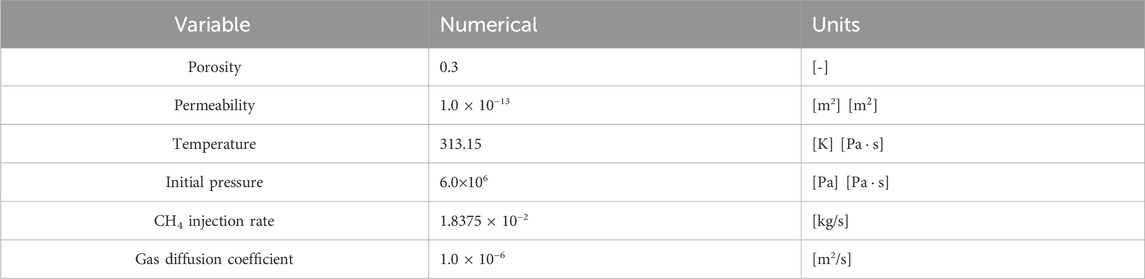
TABLE 1. Parameter properties of the simulation.
The simulation results are shown in Figure 2. As the CH4 is injected, the CO2 component is continuously pushed towards the right side of the reservoir, and the diffusion zone gradually increases. The distance between the center of the mixed zone and the wellhead gradually increases, the movement rate gradually decreases. This is consistent with the model results of Oldenburg, indicating the applicability and accuracy of this model in gas diffusion problems.
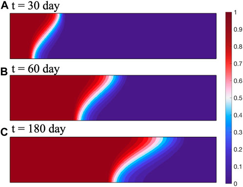
FIGURE 2. Simulation results at (A) 30 days, (B) 60 days, and (C) 180 day.
4 Model setup
We set up a reservoir model with a reservoir plane size of 6000 m × 4000 m. The reservoir is homogeneous and isotropic. The initial water saturation of the reservoir is 0.3, and the rest gas is CH4. The initial reservoir pressure is 12 MPa, the absolute permeability is
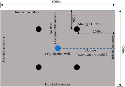
FIGURE 3. Geometry and boundary conditions of the simulation.
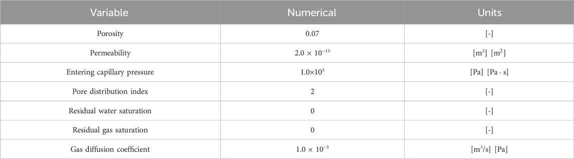
TABLE 2. Case parameter settings.
5 Simulation results
In this section, we discussed CO2 enhanced CH4 recovery based on the two-phase multi-component seepage equation. Due to the geometric distribution of CO2 injection wells and CH4 extraction wells being symmetric in the simulation domain, in order to improve computational efficiency, we only analyzed a quarter of the CO2 displacement CH4 process.
As shown in Figure 4, after CO2 is injected into the reservoir, CH4 inside the reservoir is replaced. The gas pressure of CH4 near the CO2 injection well sharply decreases, and as the extraction progresses, CO2 diffuses towards the vicinity of the extraction well. Near the extraction well, CH4 pressure decreases uniformly, and CH4 is extracted through the extraction well.
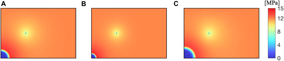
FIGURE 4. (A) 100 days, (B) 300 days, and (C) 500 days results of CH4 pressure in reservoirs.
As shown in Figure 5, after CO2 is injected into the reservoir, CH4 and reservoir water are driven away together, forming a CO2 enrichment zone near the injection well. Near the extraction well, due to the lower well pressure, water and CH4 are extracted together, decreasing the water saturation.
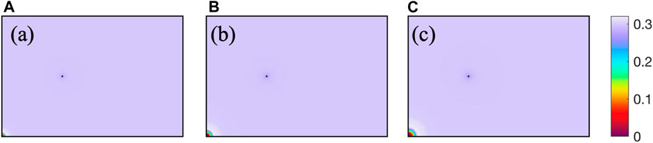
FIGURE 5. (A) 100 days, (B) 300 days, and (C) 500 days reservoir water saturation results.
We study the CH4 production and daily productivity, as shown in Figure 6, of the extraction wells. Among them, the daily productivity of CH4 shows a power-law decreasing trend, with CH4 productivity reaching its maximum in the early stages of extraction; As extraction proceeds, the daily CH4 production rate decreases due to the decrease in reservoir pressure. In the later stage of extraction, CH4 productivity reaches equilibrium and remains basically unchanged. The growth rate of production decreases as extraction progresses.
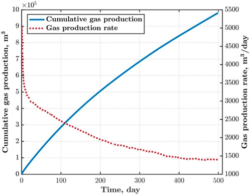
FIGURE 6. CH4 production volume and daily productivity.
6 Sensitive analysis
6.1 Effect of porosity
In this section, we investigage the distribution of CH4 pressure, water saturation, and evolution of CH4 extraction under different reservoir porosities of 0.0175, 0.035, 0.14, and 0.21.
Porosity of reservoir has a significant impact on CH4 pressure distribution. As shown in the Figure 7, the smaller the porosity of the reservoir, the greater the impact range of CO2 injection of the same quality. This is because the reduction of pore space results in the same volume of CO2 occupying a larger reservoir area. When the porosity of the reservoir is 0.0175, the CO2 injection well and the CH4 production well are connected, and all the CH4 in the middle is driven out. When the porosity is greater than 0.14, the influence of porosity on pore pressure decreases.
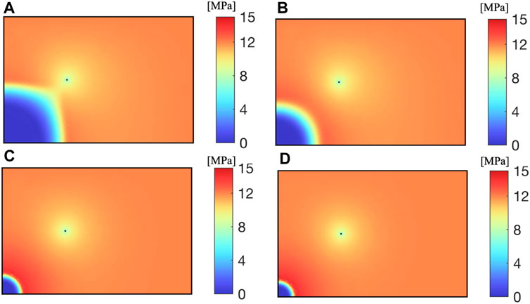
FIGURE 7. CH4 pressure with different porosities: (A): 0.0175 (B): 0.035 (C): 0.14 (D): 0.21.
As shown in Figure 8, the larger the porosity, the larger the pore volume of the same area reservoir, and more CO2 needs to be injected to expand its influence area; The smaller the porosity, the larger the impact area of the same CO2 injection amount, and more CH4 and water from the reservoir pores are driven out by CO2.

FIGURE 8. Water saturation at different porosities: (A): 0.0175 (B): 0.035 (C): 0.14 (D): 0.21.
As shown in Figure 9, with the increase of porosity, the CH4 extraction rate increases; The larger the porosity, the more CH4 stored near the extraction well. Under the same production well pressure and CO2 injection rate, the greater the CH4 production.
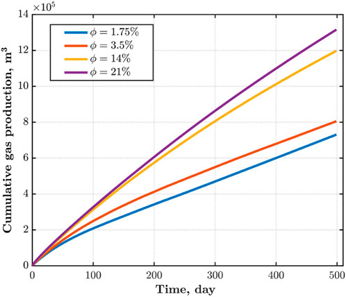
FIGURE 9. CH4 production.
6.2 Effect of permeability
In this section, we investigage the distribution of CH4 pressure, water saturation, and evolution of CH4 extraction with permeability being with
The permeability of the reservoir determines the migration ability of fluids in the reservoir. As shown in Figure 10, the higher the permeability of the reservoir, the faster CO2 diffuses from the injection well to the surrounding area at the same time. When the permeability is
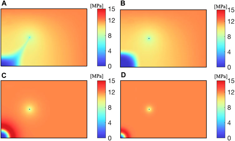
FIGURE 10. CH4 pressure at different permeabilities (A):
As shown in Figure 11, the influence range of extraction and injection wells is highly correlated with the reservoir permeability. Within the same extraction time, reservoirs with higher permeability can produce more CH4; Reservoirs with low permeability face greater difficulties in both CO2 injection and CH4 extraction, resulting in lower CO2 recovery efficiency.
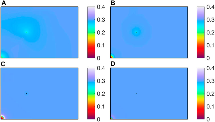
FIGURE 11. Water saturation at different permeabilities: (A):
Permeability has a great impact on CH4 production. As shown in Figure 12, the greater the permeability, the more CH4 extraction However, blindly increasing the permeability of the reservoir has a saturation value for the increase in CH4 production. When the permeability of the reservoir increases from
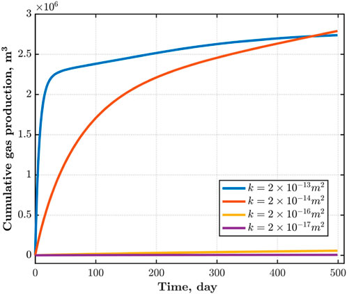
FIGURE 12. CH4 production under different permeabilities.
6.3 Effect of CO2 injection rate
In this section, we investigage the distribution of CH4 pressure and water saturation with injection rate being with
As shown in Figure 13, the higher the CO2 injection rate, the greater the reservoir pressure, and the larger the range of CO2 diffusion. Due to CO2 injecting water and CH4 into the pores of the reservoir near the well, the CH4 pressure near the CO2 injection well decreases, forming a high-pressure zone at the front of the displacement.
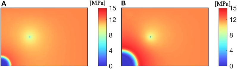
FIGURE 13. CH4 pressure at different injection rates (A):
As shown in Figure 14, for water saturation at different injection rates. The higher the CO2 injection rate, the more water and CH4 are discharged at the same time, forming a low saturation zone near the injection well. For CH4 extraction wells, the high pressure brought by high injection rates leads to more CH4 being extracted, and the high CO2 injection rate increases CH4 extraction.
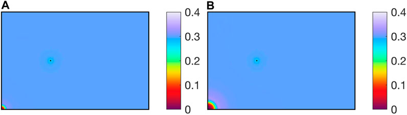
FIGURE 14. Water saturation at different injection rates (A):
7 Conclusion
The process of CO2-enhanced CH4 extraction involves the intricate migration dynamics of gas and water phases, incorporating multiple components within the reservoir. Leveraging the derived two-phase flow and multi-component diffusion model, we present a comprehensive numerical model to elucidate the intricate phenomena associated with the multi-component seepage of CO2-EGS. This model considers both the water phase and the gas phase, encompassing two distinct components: CO2 and CH4. The main conclusions are derived as follows.
1) With the injection of CO2, both water and CH4 within the reservoir pores are displaced. The CH4 productivity exhibits a power-law decline, ultimately stabilizing at a constant extraction rate, with a progressively diminishing gradient of productivity increase. In the initial extraction stages, the CH4 production rate attains its peak, declining subsequently due to the diminishing reservoir pressure. In the latter stage of extraction, CH4 productivity reaches an equilibrium state, demonstrating sustained constancy.
2) Higher porosity levels result in augmented CH4 reserves proximate to extraction wells. However, heightened porosity diminishes the influence of CO2 on CH4 recovery, as it reduces the area affected by the reservoir pressure of CO2. Conversely, lower porosity levels extend the influence of a given CO2 injection volume over a larger reservoir range, driving out CH4 and water over an expansive area.
3) Elevated reservoir permeability accelerates CO2 diffusion from injection wells to the surrounding region. While increased permeability enhances CH4 production, an indiscriminate escalation of permeability reaches a saturation point for CH4 production augmentation. Excessive permeability poses the risk of connecting CO2 injection wells with CH4 extraction wells, impeding CH4 extraction upon CO2 breakthrough.
4) The CO2 injection rate directly influences the affected area within the reservoir. A higher injection rate results in increased reservoir pressure, leading to greater CH4 extraction and improved production. Nonetheless, an excessively high CO2 injection rate induces heightened reservoir pressure, potentially causing cap rock damage and consequent CO2 release.
Data availability statement
The original contributions presented in the study are included in the article/Supplementary material, further inquiries can be directed to the corresponding author.
Author contributions
XW: Conceptualization, Methodology, Project administration, Visualization, Writing–original draft. QZ: Formal Analysis, Methodology, Visualization, Writing–original draft. YW: Investigation, Methodology, Writing–review and editing.
Funding
The author(s) declare that no financial support was received for the research, authorship, and/or publication of this article.
Acknowledgments
A special acknowledgment goes to the reviewers for their invaluable feedback.
Conflict of interest
Authors XW, QZ, and YW were employed by Shaanxi Yanchang Petroleum (Group) Co., Ltd.
Publisher’s note
All claims expressed in this article are solely those of the authors and do not necessarily represent those of their affiliated organizations, or those of the publisher, the editors and the reviewers. Any product that may be evaluated in this article, or claim that may be made by its manufacturer, is not guaranteed or endorsed by the publisher.
References
Bachu, S. (2000). Sequestration of CO2 in geological media: criteria and approach for site selection in response to climate change. Energy Convers. Manag. 41 (9), 953–970. doi:10.1016/s0196-8904(99)00149-1
Bonder, L. (1992). Applications of carbon dioxide in enhanced oil recovery. Energy Convers. Manag. 33 (5), 579–586. doi:10.1016/0196-8904(92)90059-6
Busch, A., Gensterblum, Y., Krooss, B. M., and Siemons, N. (2006). Investigation of high-pressure selective adsorption/desorption behaviour of CO2 and CH4 on coals: an experimental study. Int. J. Coal Geol. 66 (1-2), 53–68. doi:10.1016/j.coal.2005.07.003
Damen, K., Faaij, A., Van, F., Gale, J., and Lysen, E. (2005). Identification of early opportunity for CO2 sequestration-worldwide screening for CO2-EOR and CO2-ECBM projects. Energy 30 (10), 1931–1952. doi:10.1016/j.energy.2004.10.002
Goetz, V., Pupier, O., and Guillot, A. (2006). Carbon dioxide-methane mixture adsorption on activated carbon. Adsorption 12 (1), 55–63. doi:10.1007/s10450-006-0138-z
Hamza, A., Hussein, I. A., Al-Marri, M. J., Mahmoud, M., Shawabkeh, R., and Aparicio, S. (2021). CO2 enhanced gas recovery and sequestration in depleted gas reservoirs: a review. J. Petroleum Sci. Eng. 196, 107685–685. doi:10.1016/j.petrol.2020.107685
Jessen, K., Tang, G., and Kovscek, A. (2008). Laboratory and simulation investigation of enhanced coalbed methane recovery by gas injection. Transp. Porous Media 73 (2), 141–159. doi:10.1007/s11242-007-9165-9
Katayama, Y. (2023). “Study of coalbed methane in Japan,” in Proceedings of united nations international conference on coalbed methane development and utilization (Beijin), 238–243.
Kurniawan, Y., Bhatia, S., and Rudolph, V. (2006). Simulation of binary mixture adsorption of methane and CO2 at supercritical conditions in carbons. AIChE J. 52 (3), 957–967. doi:10.1002/aic.10687
Li, J. (2015). Mathematical simulation of effect of different coal particle shapes on gas desorption diffusion Law. Saf. Coal Mines 46 (1), 1–4.
Liang, W., Wu, D., and Zhao, Y. (2010). Experimental study of coal beds methane replacement by carbon dioxide. Chin. J. Rock Mech. Eng. 29 (4), 665–673.
Liu, Q., Wang, Y., Wang, M., et al. (2005a). Trends of greenhouse gases in recent 10 years in Beijing. Chin. J. Atmos. Sci. 29 (2), 267–271.
Liu, Y., Li, X., and Bai, B. (2005b). Preliminary estimation of CO2 storage capacity of coalbeds in China. Chin. J. Rock Mech. Eng. 24 (16), 2947–2952.
Li, X., and Bai, B. (2005). Preliminary estimation of CO2 storage capacity of coalbeds in China. Chin. J. Rock Mech. Eng. 24 (16), 2947–2952.
Ma, T., Jiang, L., Shen, W., Cao, W., Guo, C., and Nick, H. M. (2023). Fully coupled hydro-mechanical modeling of two-phase flow in deformable fractured porous media with discontinuous and continuous Galerkin method. Comput. Geotechnics 164, 105823. doi:10.1016/j.compgeo.2023.105823
Ma, T., Zhang, K., Shen, W., Guo, C., and Xu, H. (2021). Discontinuous and continuous Galerkin methods for compressible single-phase and two-phase flow in fractured porous media. Adv. Water Resour. 156, 104039. doi:10.1016/j.advwatres.2021.104039
Martin, V., Jaffr´e, J., and Roberts, J. E. (2005a). Modeling fractures and barriers as interfaces for flow in porous media. SIAM J. Sci. Comput. 26, 1667–1691. doi:10.1137/s1064827503429363
Martin, V., Jaffr´e, J., and Roberts, J. E. (2005b). Modeling fractures and barriers as interfaces for flow in porous media. SIAM J. Sci. Comput. 26, 1667–1691. doi:10.1137/s1064827503429363
Nie, B., He, X., and Wang, E. (2000). Mechanism and modes of gas diffusion in coal seams. China Saf. Sci. J. 10 (6), 24–28.
Oldenburg, C. M. (2003). Carbon dioxide as cushion gas for natural gas storage. Energy fuels. 17, 240–246. doi:10.1021/ef020162b
Pei, K., Sun, S., and Huang, L. (2005). Global warming and carbon dioxide mitigation. Energy Conserv. Technol. 23 (3), 239–243.
Qin, Y., Wang, C., Wang, J., et al. (2012). Mathematical model of gas emission in coal particles and the numerical solution. J. China Coal Soc. 37 (9), 1466–1471.
Qin, Y., Yongjiang, H., Wang, Y., et al. (2013). Numerical solution of gas emission in coal particle based on two kinds of mathematical model. J. China Univ. Min. Technol. 42 (6), 923–928.
Theodore, T., Hiren, P., Fayyaz, N., Racherla, D., Knackstedt, M. A., and Sahimi, M. (2004). Overview of laboratory and modeling studies of carbon dioxide sequestration in coal beds. Industrial Eng. Chem. Res. 43 (12), 2887–2901. doi:10.1021/ie0306675
U S Department of Energy, Office of Fossil Energy and National Energy Technology Laboratory (2005). Carbon sequestration, technology roadmap and program plan. [S. l.]: U. S. Department of Energy Office of Fossil Energy and National Energy Technology Laboratory.
Wang, J. (2015). Numerical simulation research of gas emission in coal particles based on Darcy' s law. J. Henan Polytech. Univ. Nat. Sci. 34 (4), 459–462. 531.
Weiyang, A. I. N., and Chen, J. (2005). Capture and separation of greenhouse gases CO2—the challenge and opportunity for separation technology. Chem. Industry Eng. Prog. 24 (1), 1–4.
Wu, D., Hao, S., and Liang, W. (2008). Development of coal bed methane displacement with carbon dioxide [J]. Shanxi Coal 28 (3), 10–14. doi:10.3969/j.issn.1672-5050.2008.03.005
Xu, J., Zhang, J., Pan, X., et al. (2005). Current status of carbon dioxide storage technologies. Coal Convers. 28 (3), 80–85.
Keywords: CO2 geological storage, CO2-EGR, two-phase flow, multi-component diffusion, low permeability reservoir
Citation: Wang X, Zhang Q and Wan Y (2024) A two-phase, multi-component model for efficient CO2 storage and enhanced gas recovery in low permeability reservoirs. Front. Energy Res. 12:1373851. doi: 10.3389/fenrg.2024.1373851
Received: 20 January 2024; Accepted: 28 February 2024;
Published: 13 March 2024.
Edited by:
Jiehao Wang, Chevron, United StatesReviewed by:
Jianwei Tian, Technical University of Denmark, DenmarkJun Liu, Sichuan University, China
Copyright © 2024 Wang, Zhang and Wan. This is an open-access article distributed under the terms of the Creative Commons Attribution License (CC BY). The use, distribution or reproduction in other forums is permitted, provided the original author(s) and the copyright owner(s) are credited and that the original publication in this journal is cited, in accordance with accepted academic practice. No use, distribution or reproduction is permitted which does not comply with these terms.
*Correspondence: Yongping Wan, eW9uZ3Bpbmd3MTlAMTYzLmNvbQ==, d2FuaHVudGVyQDE2My5jb20=