 Feng Li1
 Sui Peng
 Zhiheng Zhao
- 1Grid Planning and Research Center, Guangdong Power Grid Corporation, CSG, Guangzhou, China
- 2School of Intelligent Engineering, South China University of Technology, Guangzhou, China
- 3College of Information Science and Engineering, Northeastern University, Shenyang, China
The modular multilevel converter based high voltage direct current (MMC-HVDC) is a dynamic power balancing system. The control system of MMC generally adopts a dual closed-loop vector control strategy based on the traditional instantaneous power model under asymmetric grid state, which has complex control structure and low control accuracy. This paper introduces a flexible instantaneous power model and establishes a general power equation with active power and new reactive power as control objects. Based on this, an improved sliding-mode MMC-HVDC direct power control strategy based on the new instantaneous power model is proposed which combines the flexible instantaneous power model and the improved sliding-mode control method to eliminate the twice grid-frequency ripples in both active and reactive power under asymmetric grid states. Furthermore, it omits the inner-loop controller and power compensation terms while optimizing the control structure. Simulation results show that the proposed method has better dynamic responsiveness, control accuracy and robustness under operating conditions such as asymmetric grid state and parameter perturbation which can better exploit the advantages of the flexible instantaneous power model.
1 Introduction
Under the background of the “double carbon” goal, the research of new energy development and utilization technology has ushered in a new development boom. With the development of onshore wind power tends to be saturated, offshore wind power has become an crucial development direction of new energy, and offshore wind power has the advantages of stable resource conditions and high energy efficiency. With the continuous expansion of the construction scale and capacity of offshore wind power projects, the layout of offshore wind farms has gradually changed from near distance and small capacity to far-reaching sea and large-scale. Flexible HVDC transmission technology, with its advantages of flexible control, low switching loss and high modularity, has become one of the ideal solutions for large-scale remote offshore wind farms. However, the traditional sliding mode control of MMC-HVDC in asymmetric offshore wind power flexible and straight system has become a concern.
Modular multilevel converter (MMC) has become the most promising multilevel converter topology for high-power power electronics applications due to its high modularity, scalability, and high quality of output waveforms compared with the traditional two- and three-level voltage source converter (VSC). The MMC realizes high-voltage energy conversion function by stacking a large number of different types of submodules such as half-bridge, full-bridge, etc., which has shown a rising trend in domestic DC engineering applications (Yang et al., 2023b; Raju et al., 2019; Ma et al., 2021).
MMC is an crucial part of the DC transmission system, and the control strategy of MMC is crucial for the stable operation of the whole system. Currently, the mainstream design scheme of MMC-HVDC control system is the direct current control strategy (vector control) characterized by fast current feedback, which takes the specific form of double closed-loop series control, and can obtain high-quality current response. The implementation of this method in the synchronous rotating coordinate system (dq coordinate system) has been studied (Vasiladiotis and Cherix, 2014; Nami et al., 2015; Haiyu et al., 2023). Sliding mode variable structure control (SMC), as a classical nonlinear control method, has the advantages of good steady-state accuracy, dynamic performance, and interference immunity, and has been widely used in scenarios such as PWM rectifiers, synchronous generators, wind turbine systems, and AC/DC converters (Li et al., 2020; Fekik et al., 2021). Literature (Li et al., 2020) investigated the application of sliding mode variable structure control in MMC vector control and proposed an MMC improved sliding mode control strategy with better dynamic response capability, interference immunity, and smaller jitter. However, the above mentioned control strategies are discussed under symmetrical grid condition. In engineering practice, three-phase voltages are often asymmetrical due to grid harmonics and asymmetrical faults (Wang, 2020; Freytes, 2021), resulting in two-fold fluctuations of active and reactive power output from the MMC, which seriously affects the operational performance of the MMC-HVDC (Kong et al., 2013).
Therefore, in order to improve the transient control performance of AC/DC converter under asymmetric grid conditions, scholars in various countries have conducted a lot of research on it, and the mainstream transient control strategies of MMC are currently categorized into the dual closed-loop vector control strategy and the direct power control strategy that takes active power and reactive power as the control objects. The dual closed-loop vector control strategy is divided into the PI control strategy based on the dq coordinate system (Du et al., 2022) and the PR control strategy based on the αβ coordinate system (Semih et al., 2021), which can control the positive and negative sequence currents, but the control structure is more complicated and the control effect is affected by the performance of the phase-locked loop. In contrast, the direct power control strategy (Shang et al., 2011; Alessandra et al., 2023; Habib et al., 2023; Ping et al., 2023) establishes the control model with active and reactive power, omits the current inner loop, and simplifies the design of the control system. Literature (Shang et al., 2011) proposes a direct power control strategy for grid-connected inverters by combining the αβ coordinate system, and effective suppression of active and reactive power two-fold fluctuations can be realized by calculating the power compensation components. Literature (Habib et al., 2023) proposes a direct power control strategy based on resonant regulator for PWM rectifiers, which can realize the control of active and reactive power fluctuation components by constructing the DC voltage-power closed loop and resonant closed loop. Literature (Ping et al., 2023) and literature (Alessandra et al., 2023) used sliding mode variable structure control and differential-free beat control for direct power control of VSC and MMC, respectively, by adding a power compensation term to guarantee that the grid-side current is free of distortion. Literature (Mei et al., 2021a) proposed a power sliding mode variable structure compensation strategy, which can suppress the power fluctuation component of the two-fold frequency without guaranteeing the distortion-free grid-side current, but it cannot completely eliminate the power fluctuation of the two-fold frequency.
The control strategies described in the above literature are all based on the traditional instantaneous power definition, which is not able to eliminate the active and reactive power two-fold fluctuations while maintaining the grid-side current without distortion under asymmetrical grid conditions. In order to solve this problem, a flexible instantaneous reactive power definition is proposed in literature (Suh and Lipo, 2006) to make it applicable to the operation conditions of asymmetrical grids. In literature (Zhang and Qu, 2015) and literature (Mei et al., 2021b), the flexible instantaneous power model is applied in combination with predictive control and reduced-order vector control, respectively, and shows excellent control performance under asymmetrical grid conditions.
Sliding mode control (SMC) is a special class of nonlinear control, can control the system in accordance with the predetermined “sliding mode” state trajectory movement, has a fast response, does not depend on the mathematical model of the controlled object, strong resistance to external interference, etc. (Farzin and Mehdi, 2023), is widely used in synchronous generators, wind turbine systems and other systems. It is widely used in synchronous generators, wind turbine systems and other systems. However, the jitter problem is an important issue that cannot be avoided in the sliding mode variable structure control, the traditional sliding mode control adopts the linear sliding mode surface, convergence law and other methods, but the restraining ability of the jitter is insufficient to ensure the convergence rate at the same time (Mohapatra et al., 2023), and the fractional-order sliding mode method, a new type of convergence law, quasi-sliding mode method, and other strategies are respectively proposed to inhibit the jitter phenomenon in the literature (Pratap et al., 2018; Weijia et al., 2023; Xinxin et al., 2023), but there are still some problems in the design of the controller, the control accuracy, etc. The control of the sliding mode control is a very important issue.Literature (Rui et al., 2020; Li et al., 2021; Wang et al., 2021) proposes an adaptive (two-layer) stochastic approach, a droop coefficients stability region analysis approach and a reduced-order small-signal closed-loop transfer function model. However, there are still some problems in controller design, control accuracy, etc.
In order to further explore the application of flexible instantaneous power model in MMC transient control and to reduce the jitter problem of conventional sliding mode control, this paper proposes an improved sliding mode MMC-HVDC direct power control strategy based on flexible instantaneous power model, which combined with the flexible instantaneous power model can eliminate the two-fold fluctuation of MMC output active and reactive power under the asymmetric grid state and keep the current of the AC side free of aberration, and at the same time, compared with the traditional PI control strategy and the conventional sliding mode control, it has obvious advantages in terms of the dynamic responsiveness, robustness, and anti-jitter.
This paper firstly introduces the topology and mathematical model of MMC; Compares and analyzes the flexible instantaneous power model with the traditional instantaneous power model, and derives the power control equation of MMC based on the flexible instantaneous power model, proposes the direct power control method of MMC based on the improved sliding-mode control strategy, and analyzes in depth the control performance of the improved sliding-mode control strategy, and finally builds a simulation model and constructs an experimental platform for the MMC hardware in the loop in PSCAD/EMTDC, and conducts a comparative simulation and experimental validation for the proposed control strategy under the voltage symmetry, asymmetric conditions, and parameter perturbation conditions.
2 MMC mathematical model
The typical three-phase topology of the MMC is shown in Figure 1, where each phase bridge arm consists of N series-connected sub-modules (sub-modules, SM), the bridge arm equivalent resistor R0, and the bridge arm reactor L0, upk and unk (k = a,b,c, hereinafter) are the sum of the sub-module voltages of the bridge arms of each phase, and ipk and ink denote the bridge arm currents of each phase, and each phase voltage output from each phase bridge arm generates N+1 levels, which are approximated as sinusoids by the nearest level modulation strategy. On the AC side of the MMC, O and O′ denote the neutral point of the DC and AC sides, respectively (UOO' = 0), the three-phase equivalent resistance and inductance are denoted as Rac and Lac, respectively, Usk is the equivalent power supply of the AC side, and ivk is the exit three-phase current of the MMC.
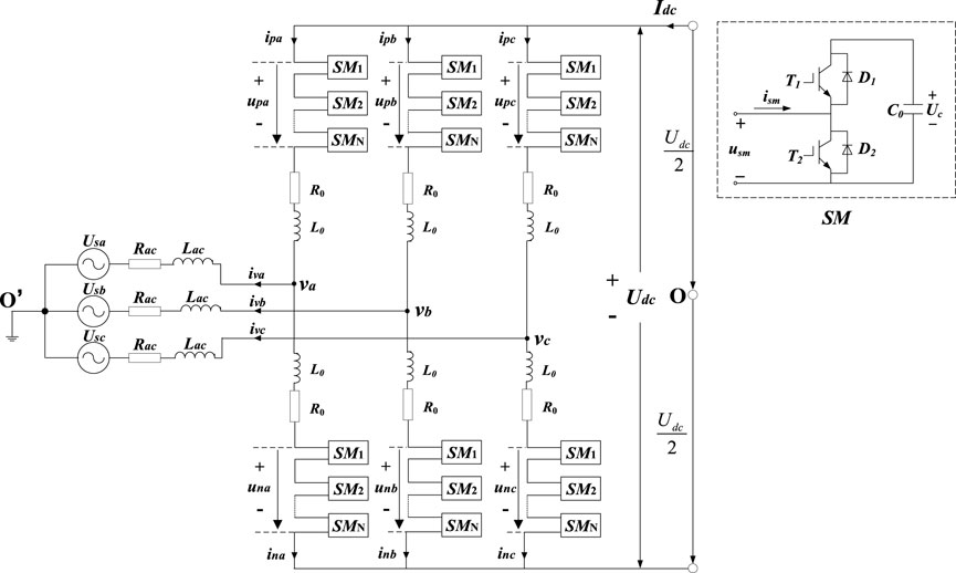
FIGURE 1. MMC circuit.
Figure 1 shows that each bridge arm of the MMC converter is composed of N submodules with the same structure and bridge arm reactors connected in series. Each submodule contains an IGBT half-bridge and an energy storage capacitor C0. The control of the MMC can be realized by controlling the on-off of the IGBT through the modulation strategy and thus casting and switching the submodule.
According to Kirchhoff’s voltage law, the mathematical model of the AC side and DC side of the MMC can be obtained by deriving the circuit of each bridge arm of the MMC:
in the formula:
Udiffk is the differential mode voltage of the k-phase upper and lower bridge arms of the MMC; Ucomk is the common-mode voltage of the k-phase upper and lower bridge arms of the MMC; and ilk is the internal loop current of the MMC.
The mathematical model Eq. 1 of the AC side of the MMC is Clark transformed to transform the sinusoidal AC quantities in the three-phase stationary coordinate system to the sinusoidal AC quantities in the two-phase αβ stationary coordinate system, and then the mathematical model of the MMC in the two-phase αβ stationary coordinate system can be expressed as follows:
where Usα and Usβ are the α and β-axis components of Usk, ivα and ivβ are the α and β-axis components of ivk, respectively; Udiffα and Udiffβ are the α and β-axis components of Udiffk, respectively.
3 MMC power modeling based on flexible instantaneous power modeling
3.1 Flexible transient power modeling
The conventional instantaneous power model can be expressed as (Lu and Ooi, 2007):
where: * denotes the conjugate, Uαβ and iαβ are the α and β axis components of the voltage and current on the AC side of the grid, respectively.
Under asymmetrical grid conditions, the MMC power control strategy based on the traditional instantaneous power model cannot simultaneously eliminate the two-fold frequency fluctuation components of active and reactive power while ensuring that the current on the AC side has no distortion. Meanwhile, under the asymmetrical and non-ideal grid conditions, only the instantaneous active power has practical physical and mathematical significance. Therefore, in this paper, a flexible instantaneous power model is introduced to redefine the expression of instantaneous reactive power, which is more applicable to the non-ideal grid with asymmetrical three-phase voltages.
The flexible instantaneous power model is mainly improved for the expression of instantaneous reactive power, which is expressed as the real part of the product of the voltage delay vector conjugated to the current vector with the expression:
where:
When the three-phase voltages are symmetrical, the negative sequence components do not exist, and the expressions for the two instantaneous reactive powers are the same from Eq. 6, viz:
When the three-phase voltage is asymmetrical, the instantaneous vectors of voltage and current in the αβ coordinate system can be expressed as:
where:
Bringing Eq. 9 into Eq. 6 yields an expression for the flexible instantaneous power model in the αβ coordinate system as:
in the formula:
Combining Eq. 9 and Eq. 10 gives the expression for each power component as:
From Eq. 10, it can be seen that the active power and reactive power in the flexible instantaneous power model under asymmetric voltage conditions produce the direct flow P1 and Qb of the interaction of the negative sequence components of the voltage and current, respectively, on the basis of the positive-sequence components P0 and Qa, as well as the two-fold fluctuations of the interaction of the positive and negative-sequence components of the voltage and current in the two-fold fluctuations of the components P2, P3, and Qc, Qd, which are needed to be satisfied at this time if the two-fold fluctuations of the control of the active power are 0, i.e., to satisfy the P2+P3 = 0:
to write:
substituting Eq. 14 into Eq. 12 shows that:
From Eq. 15, it can be seen that under the definition of flexible instantaneous reactive power, when the two-fold fluctuation of the control instantaneous active power is zero, the sum of the two-fold fluctuation of the flexible instantaneous reactive power, Qc + Qd, is also zero, so that the direct power control strategy based on the definition of flexible instantaneous reactive power can inhibit the two-fold fluctuation of the active power and the reactive power under the condition of guaranteeing that the three-phase current does not undergo aberrant, and it is more suitable for the conditions of asymmetric three-phase voltage of the grid compared with the traditional instantaneous power model.
3.2 MMC flexible transient power modeling
From Eq. 6, the expressions for instantaneous active power and flexible instantaneous reactive power are written as respectively:
From Eq. 16, the derivatives of instantaneous active power and flexible instantaneous reactive power with respect to time t can be written as respectively:
From Eq. 9:
Bringing Eqs. 3, 4, 19 into Eqs. 17, 18 yields the MMC power model based on the flexible instantaneous power model as:
among them:
Where: W is the state variable, i.e., controlled quantity; U is the control variable, i.e., output variable; X and Y are the coefficient matrices; and Z is the perturbation variable.
4 Direct power control strategy based on improved sliding mode control
The direct power control strategy of MMC takes active power and reactive power as the control objects and usually adopts the PI control method. Although the PI control can achieve a better control effect in the steady state, the control performance is poor in the transient conditions such as parameter perturbation because of its more fixed control structure, so this paper proposes a kind of improved sliding-mode control strategy and applies it to the direct power control strategy based on the flexible instantaneous power model of MMC.
The fundamental difference between the sliding mode variable structure control and conventional PI control is the discontinuity of control, that is, the control system “structure” is based on the current state of the control system, purposeful and continuous change, forcing the system state along the pre-designed trajectory of the state of small amplitude, high frequency up and down movement until it stays at the equilibrium, as shown in Figure 2, the system state enters the sliding mode surface and moves on the sliding mode surface is called sliding mode. The process in which the system state enters the sliding mode surface and moves on the sliding mode surface is called sliding mode. When the system state enters the sliding mode, it is insensitive to external perturbations and parameter changes, and can move on the sliding mode surface according to the established design to accurately achieve the control goal, so the sliding mode variable structure control has better response speed and robustness than other conventional control methods such as PI control strategy.
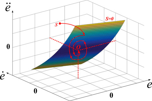
FIGURE 2. The control process of SMC.
However, the traditional sliding mode control generally adopts linear sliding mode surface and exponential convergence law method, and there exists motion inertia near the sliding mode surface, which easily leads to vibration jitter phenomenon of the controlled quantity and affects the control effect. In order to further weaken the vibration phenomenon, improve the control accuracy and reduce the steady state error, this paper proposes an improved sliding mode variable structure control and applies it to the direct power control strategy based on the flexible instantaneous power model.
4.1 Improved sliding mode control method
4.1.1 Integral sliding mold surface
The traditional linear sliding mode surface is linearized to the error function, and the rate of change of the sliding mode function is unconstrained, and the convergence speed is slow. Therefore, this paper introduces the integral type sliding mode surface function, which adds the integral term of the error function on the basis of linear processing, reduces the switching rate of the sliding mode surface function, improves the steady state accuracy, and effectively weakens the phenomenon of jitter, and the integral coefficient ks (ks>0) can regulate the change rate of the integral sliding mode surface function. The integral sliding mode surface function is expressed as:
where e is the control error.
4.1.2 Improved exponential convergence law
As a classical sliding mode control function, the exponential convergence law can optimize the motion trajectory of the system state when converging to the sliding mode surface and accelerate the rate of the system state arriving at the sliding mode surface, but due to the existence of an isovelocity term in the expression, it leads to poor convergence characteristics of the system state near the sliding mode surface, which triggers a certain degree of jitter phenomenon (Abolfazl et al., 2023). Therefore, this paper optimizes the traditional exponential convergence law and proposes an improved exponential convergence law to make it more suitable for the direct power control model of MMC:
Where p is the power of the control error; ε and k are the control coefficients, respectively, which are generally taken as normal numbers; sat(s) is the saturation function with the expression:
The control idea of the saturation function is as follows: design a boundary layer, outside the boundary layer, use the switching control sign(s), so that the system state quickly converges to the sliding mode; within the boundary layer, use the feedback control, so as to reduce the jittering phenomenon triggered by the switching control in the vicinity of the sliding mode surface.
As shown in Eq. 22, this paper introduces the power function of the control error into the design of the improved exponential convergence law, so that the motion rate of the system state and the control error produce a strong correlation, when the system state is far away from the surface of the sliding mold, the control error is larger, the convergence rate of the system state is increased, and the convergence effect is significantly strengthened; when the system state is close to the surface of the sliding mold, the control error is small, and the convergence rate of the system state is lowered, so that the system state achieves a “soft landing” on the sliding mold surface. When the system state is close to the sliding mold surface, the control error is small, the system state convergence rate is reduced, which reduces the motion inertia of the system state and enables the system state to achieve a “soft landing” on the sliding mold surface, and effectively suppresses the jitter vibration phenomenon generated in the process of convergence of the sliding mold. At the same time, the traditional switching function sgn(s) is replaced by the saturation function sat(s), which reduces the step transformation of the lower boundary motion on the sliding mode surface, further weakening the vibration phenomenon. Therefore, the improved exponential convergence law proposed in this paper effectively balances the needs of convergence rate and jitter weakening.
4.1.3 Stability analysis
In order to ensure the stability of the proposed improved sliding mode control strategy, this paper applies the Liapunov’s second stability method (Yang et al., 2023a) for stability analysis, for the improved sliding mode control method shown in Eq. 22, a Liapunov function can be constructed as:
where: H is the stabilization factor, taken as a normal number.
For the improved sliding mode control strategy proposed in this paper, s represents the sum of the power tracking error and its integral term, and when the derivative of the square of the power error with respect to time is negatively definite, it represents that the active and reactive power output from the MMC can achieve the control objective. Taking the derivative with respect to time for Eq. 24 yields:
where is the first order derivative of the Lyapunov function.
Combining Eq. 24 and Eq. 25, it can be seen that, it is positive definite, and its derivatives are negative definite in the case of s ≠ 0, which satisfies the criterion of Liapunov’s second stability method, and it can be proved that the proposed improved sliding mode control method satisfies the asymptotic stabilization condition, and can achieve the power control objective.
4.2 Design of direct power controller based on improved sliding mode control
According to the flexible instantaneous power state Eq. 17, the control objectives are set to be P→Pref and Q→Qref, respectively, so that e1 = Pref -P, e2 = Qref -Q, and the switching functions are designed as follows according to the design method of the integral sliding mode surface, respectively:
where: ks1, ks2 are normal numbers.
The design method of the improved convergence law in combination with Eq. 19 can be obtained:
where:k1, k2, ks1, ks2, ε1, ε2, p, q are all positive constants.
Combining Eqs. 20, 27, 28 yields the expressions for the command values Udiffdref and Udiffqref of the differential mode voltage of the control variables in the direct power control system as:
among them:
4.3 Overall system control strategy
Figure 3 shows the block diagram of the improved sliding mode power control strategy for MMC-HVDC based on flexible instantaneous power model proposed in this paper. As shown in Figure 2, the active power and flexible reactive power deviation are calculated in real time by the flexible instantaneous power model, and the reference value of the control variable, i.e., the αβ-axis component of the differential-mode voltage, Udiffαβref, is obtained by the improved sliding-mode direct power controller, Eq. 29, and the trigger signals of the IGBTs in the sub-modules are obtained by the coordinate transformation and combined with the circulating current suppression controller and the nearest-level modulation strategy to output the constant active power and reactive power. Constant active power and reactive power.
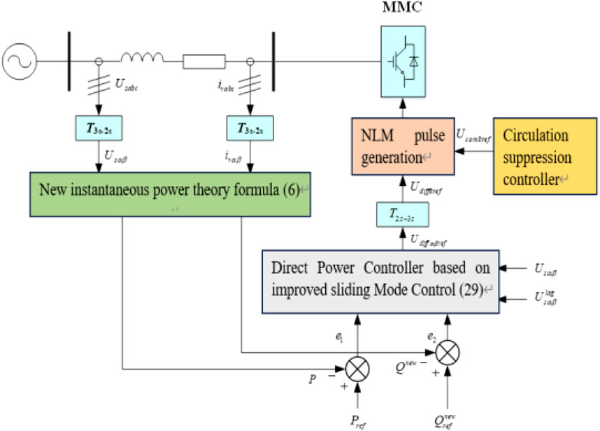
FIGURE 3. The block diagram of the proposed control strategy.
5 Simulation verification
5.1 Simulation model
In this paper, a four-terminal MMC-HVDC system as shown in Figure 4 is built in the PSCAD/EMTDC platform, and the four-terminal system adopts the master-slave control strategy (Lu and Ooi, 2007), MMC4 controls the DC voltage of the system from the master station, and MMC1-MMC3 are the slaves using constant power control, where MMC2 adopts the direct power control strategy proposed in this paper. The simulation parameters are calculated and shown in Table 1. The positive direction of power is defined as the flow from AC side to DC side.
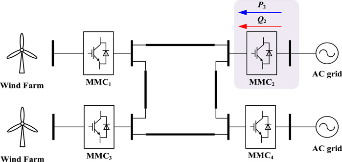
FIGURE 4. Four-terminal MMC-based HVDC system.
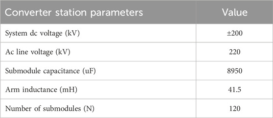
TABLE 1. Parameters of MMC2.
In order to verify the effectiveness of the proposed improved sliding mode direct power control strategy for MMC-HVDC based on flexible instantaneous power model, in this paper, comparative simulation experiments have been carried out by applying different power definitions and different controllers in MMC2 under voltage symmetrical, asymmetrical conditions, and parameter perturbation conditions, respectively, as shown in Figure 5-Figure 8.
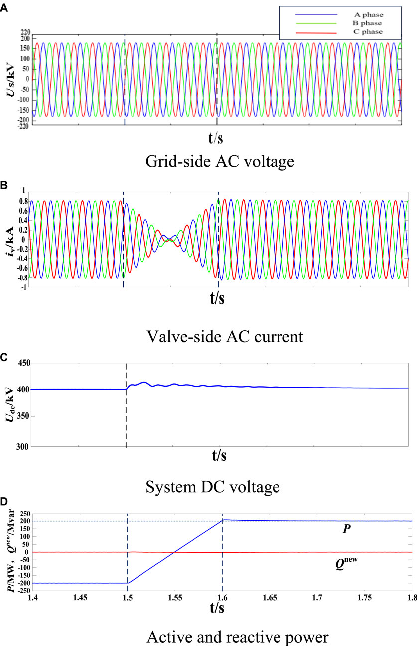
FIGURE 5. Simulation results under balanced grid condition: (A) Grid-side AC voltage (B) Valve-side AC current (C) System DC voltage (D) Active and reactive power.
5.2 Steady state operation
In order to verify the steady state and dynamic performance of MMC2 at different powers after applying the proposed improved sliding mode direct power control strategy, this subsection analyzes the steady state control performance of MMC2 under voltage symmetry conditions and simulates it for active step conditions. During the simulation, the initial reference values of active and reactive power of MMC2 are set to be −200 MW and 0 MVar, respectively. the trend reversal is set at 1.5 s, which sets the command value of active power of MMC2 to change linearly from −200 MW to 200 MW. it can be seen in Figure 5 that the improved sliding mode direct power control strategy can realize the accurate tracking of the reference values of active and reactive power, which verifies the performance of the proposed control strategy under symmetrical power conditions. the effectiveness of the proposed control strategy under symmetrical grid conditions. At 1.5 s, with the reversal of the active current, the active power output from MMC2 has a small overshoot at the beginning of the change, which can accurately track the change of the power reference value, and at the same time, the current trend of the valve side of MMC2 is smooth and always maintains the steady state operation, and the system dc voltage gradually returns to stability after the power fluctuation, which shows that the steady state performance based on the improved sliding mode direct power control strategy is good.
5.3 Asymmetric voltage transient operation
Under asymmetrical grid voltage conditions, the direct power control strategy based on the traditional instantaneous power model has limitations in suppressing the two-fold frequency fluctuation components of active and reactive power, therefore, in this section, the direct power control of MMC is carried out based on the flexible instantaneous power model to verify the validity of the flexible instantaneous power model. Meanwhile, in this section, the PI controller as well as the improved sliding mode controller are used in the power control process of MMC2 to compare the control performance of the two controllers, respectively. During the simulation process, the initial reference power of MMC2 station is set to −200 MW and 0 MVar, respectively. At 1.5 s, a 50% voltage dip is set to occur in the A-phase voltage, which leads to asymmetry of the three-phase voltages on the AC side.
Figure 6 compares the control effects based on different instantaneous power definitions when the control objective is to suppress the MMC2 output active power twofold oscillation under asymmetric grid conditions. Figures 6A–D shows the operation with the proposed strategy, and Figure 6E shows the operation when the traditional instantaneous power definition is used. At 1.5 s, a voltage dip occurs in the A-phase voltage, and an asymmetry occurs in the three-phase grid voltage, and although the active power under the control based on the traditional instantaneous power model still remains constant, there is still a doubled-frequency oscillation with the amplitude of 80 MW in the output reactive power, indicating that the traditional instantaneous power model cannot eliminate the doubled frequency oscillations in the active and reactive power under the grid voltage asymmetry at the same time. On the contrary, the active and reactive power output from the MMC2 under the control of the flexible instantaneous power model can accurately track the reference value and keep the valve-side grid current free of aberrations, indicating that the direct power control based on the flexible instantaneous power model can eliminate the doubled-frequency fluctuation components in the active and reactive power at the same time. From Figure 6C, due to the stabilization of active power control, the A-phase voltage drop causes only minor fluctuations in the DC voltage of the four-terminal system, and thus the proposed improved control strategy under asymmetrical grid voltage conditions has less impact on the four-terminal system as a whole. In conclusion, the flexible instantaneous reactive power is more suitable as a controlled variable in MMC constant power control than the conventional instantaneous reactive power.
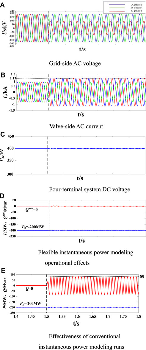
FIGURE 6. Simulation results under unbalanced grid condition: (A) Grid-side AC voltage (B) Valve-side AC current (C) Four-terminal system DC voltage (D) Flexible instantaneous power modeling operational effects (E) Effectiveness of conventional instantaneous power modeling runs.
Figure 7 compares the dynamic control responsiveness and robustness of the PI controller, the conventional sliding mode controller, and the improved sliding mode controller for direct power control under grid asymmetry conditions, where the A-phase voltage dip time is the same as in Figure 5. Under the same system parameter conditions, the MMC2 station uses the PI controller as well as the improved sliding mode controller, respectively, to make a side-by-side comparison of their response performance and robustness under voltage dips and parameter ingress.
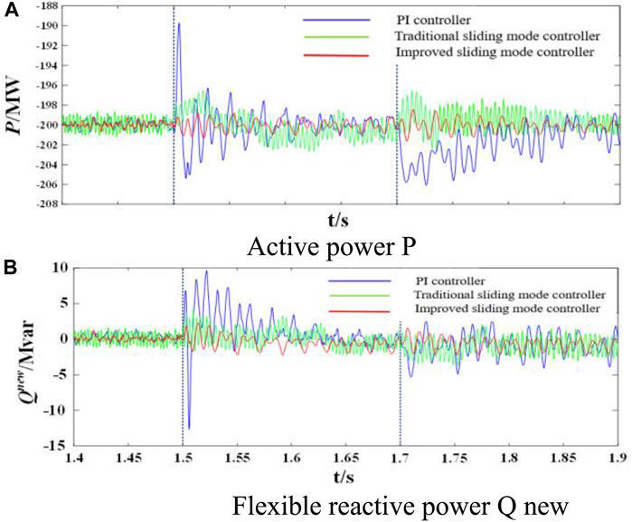
FIGURE 7. Simulation results of dynamic power responses and robustness using the PI, conventional SMC and improved SMC: (A) Active power P (B) Flexible reactive power Q new.
As can be seen from Figure 7, in the steady state operation stage, the jitter vibration of the traditional sliding mode controller is more obvious, 1.5 s when the A-phase voltage drop occurs instantly, the maximum deviation of the active power controlled by the PI controller is about 12 MW, and the overshooting amount of the active power is close to 6%, and it is only after 0.1 s that it enters into the steady state operation stage gradually. The maximum deviation of the active power controlled by the improved sliding mode controller is only 1 MW, the overshooting amount is about 1%, and it reaches the steady state operation within 0.05 s, and the vibration phenomenon is obviously weakened, which indicates that the active and reactive power under the improved sliding mode control strategy have a faster response speed, and the vibration is smaller. 1.7 s, the inductance value of the bridge arm is set from 41.5 mH to 48mH, which simulates the actual operation of the MMC, and the inductance value of the MMC is set from 1.5 mH to 48 mH. The random parameter ingress during the actual operation of the MMC is simulated. As shown in Figure 7, the perturbation by the bridge arm inductance value has a greater impact on the PI controller, and the active power instantly fluctuates to −207 MW, and gradually returns to the normal value after 0.15 s, and the steady state error increases. The traditional sliding mode controller, although the fluctuation by the parameter perturbation is small, but the jitter frequency and amplitude are larger, and the maximum amplitude of the wave is around 4 MW, whereas the active power fluctuation controlled by the improved sliding mode controller is within 2 MW, and returns to steady state error within 0.1 s. Within 0.1 s, it returns to steady state operation, and the active and reactive power can still track the command value accurately, which indicates that the improved sliding mode controller can maintain good robustness under the disturbance of the bridge arm inductance parameter change. Therefore, it is easy to know that when the direct power controller based on the flexible instantaneous power model adopts the improved sliding mode control strategy, its active and reactive power dynamic response capability is stronger and its robustness to the random parameter uptake is better, which indicates that the improved sliding mode control strategy can give full play to the advantages of the flexible instantaneous power model under the conditions of an asymmetrical grid.
6 Experimental verification
In order to verify the effectiveness of the improved sliding mode direct power control strategy for MMC-HVDC based on the flexible instantaneous power model proposed in this paper, a hardware-in-the-loop (HIL) experimental platform for modular multilevel converter is constructed in this section as shown in Figure 8. From Figure 8, the main circuit of the modular multilevel converter is realized by OPAL-RTOP5600 real-time simulation system, which operates at 105 Hz, and the controller is operated by digital signal processor (DSP). Among them, the OPAL-RT system and the DSP controller are connected through the OP8665 as an adapter board and sampling board, and the input of the DSP controller is the analog signals of the AC side and the sub-module voltages and currents output from the OPAL-RT system, and the output of the DSP controller is the digital signals of IGBT triggering computed according to the improved sliding mode direct power control strategy proposed in this paper, which is used for controlling the IGBTs in each sub-module of the MMC. The output of the DSP controller is the IGBT trigger digital signal calculated according to the improved sliding mode direct power control strategy proposed in this paper, which is used to control the on-off of the IGBTs in each sub-module of the MMC, thus realizing the external closed-loop connection between the OPAL-RT system and the DSP controller. Finally, the other components of the four-terminal MMC-HVDC system and their related controllers are embedded into the OPAL-RTOP5600 simulator and the DSP controller, and the rest of the parameters are the same as those in the simulation verification section.
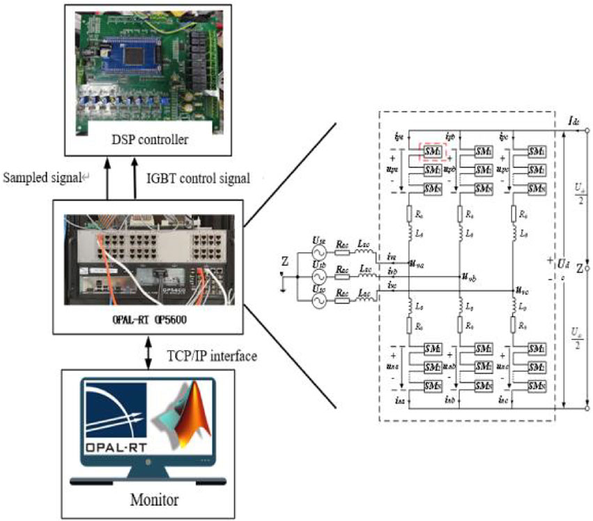
FIGURE 8. The HIL experiment topology of MMC.
Experiment 1 selects the same operating conditions as in Figure 5, and the initial reference values of active and reactive power of MMC2 are set to −200 MW and 0 MVar, respectively. the trend reversal is set at 1.5 s, and the command value of active power of MMC2 is set to change linearly from −200 MW to 200 MW. as shown in Figure 9, the active and reactive power can accurately track the reference values in the steady-state case, and the trend of the valve-side current and the system DC voltage is smooth. The trend of valve side current and system DC voltage is smooth. The above experimental results show that the improved control strategy proposed in this paper can accurately control the active power and flexible reactive power when the voltage is symmetrical.
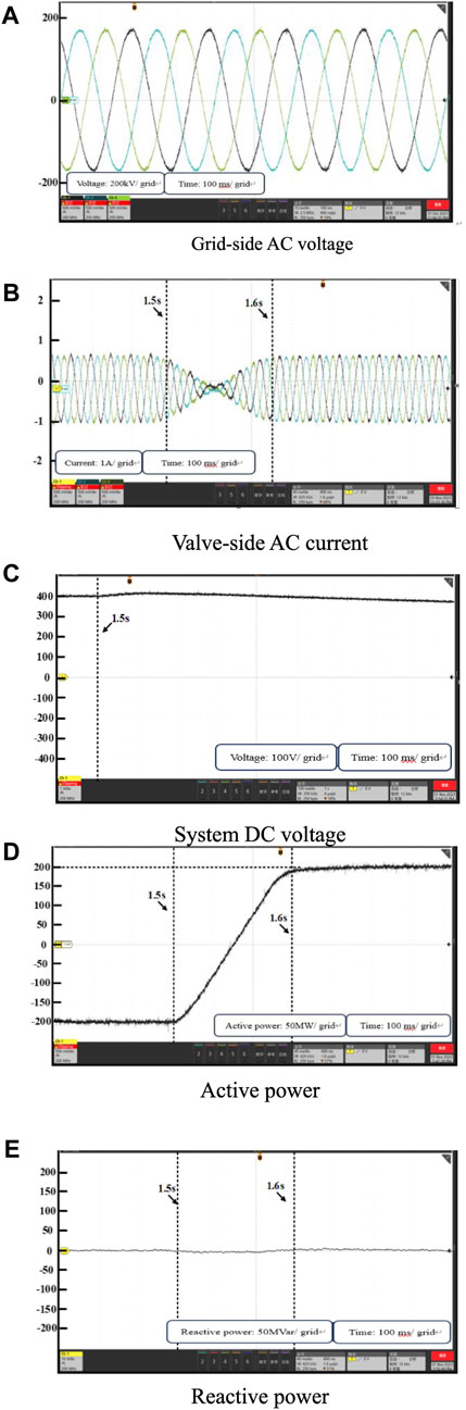
FIGURE 9. Experimental results under balanced grid condition: (A) Grid-side AC voltage (B) Valve-side AC current (C) System DC voltage (D) Active power (E) Reactive power.
Experiment 2 selects the same operating conditions as in Figure 6, and the initial reference power of the MMC2 station is set to −200 MW and 0 MVar, respectively. At 1.5 s, the setup A-phase voltage shows a 50% voltage drop, which leads to the asymmetry of the three-phase voltages on the AC side. As shown in Figure 10, after the AC voltage asymmetry occurs, the system DC voltage is more stable, and both active power and flexible reactive power can accurately track the reference value, and keep the valve-side grid current without distortion. Through the above experimental results, it can be seen that the improved control strategy proposed in this paper can accurately control the active power and reactive power when the voltage is asymmetrical.
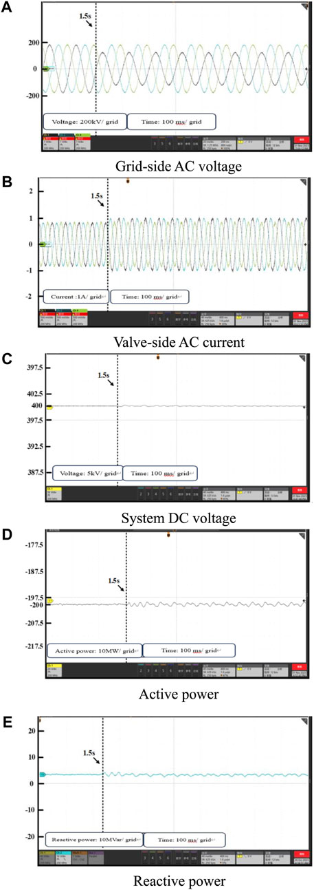
FIGURE 10. Experimental results under balanced grid condition: (A) Grid-side AC voltage (B) Valve-side AC current (C) System DC voltage (D) Active power (E) Reactive power.
It should be noted that the experimental part of this paper and the simulation part of the operating conditions are exactly the same, the controlled active power and flexible reactive power can follow the always stable tracking of the reference value, and the simulation results are roughly the same as the conclusions of the experimental results, which further illustrates the validity of the method proposed in this paper.
7 Conclude
In this paper, an improved sliding mode direct power control strategy for MMC-HVDC based on the flexible instantaneous power model is proposed, which derives the direct power control model for MMC on the basis of the flexible instantaneous power model and optimizes the control process with the improved sliding mode control strategy. Through theoretical analysis, model simulation, and experimental verification, the following conclusions are drawn:
1) The flexible instantaneous power model can simultaneously suppress the two-fold frequency fluctuation of active and reactive power under asymmetrical grid conditions, avoiding the power compensation term and optimizing the power control strategy.
2) Under asymmetric grid and random parameter perturbation conditions, the dynamic response capability and robustness of the improved sliding mode control strategy are stronger than that of the traditional PI control strategy, which is more suitable for the realization of the flexible direct power control strategy (Akagi et al., 1984).
Data availability statement
The original contributions presented in the study are included in the article/Supplementary material, further inquiries can be directed to the corresponding author.
Author contributions
FL: Conceptualization, Formal Analysis, Methodology, Writing–original draft, Writing–review and editing. SP: Conceptualization, Funding acquisition, Project administration, Supervision, Writing–original draft, Writing–review and editing. YW: Conceptualization, Resources, Software, Validation, Writing–review and editing. HY: Data curation, Formal Analysis, Project administration, Software, Writing–review and editing. ZH: Conceptualization, Formal Analysis, Investigation, Project administration, Writing–review and editing. ZZ: Data curation, Methodology, Supervision, Writing–review and editing.
Funding
The author(s) declare financial support was received for the research, authorship, and/or publication of this article. The authors would like to acknowledge the support from the Science and Technology Project of China Southern Power Grid under Grant No. 037700KK52220013.
Conflict of interest
Authors FL, SP, YW, and HY were employed by the Guangdong Power Grid Corporation.
The remaining authors declare that the research was conducted in the absence of any commercial or financial relationships that could be construed as a potential conflict of interest.
Publisher’s note
All claims expressed in this article are solely those of the authors and do not necessarily represent those of their affiliated organizations, or those of the publisher, the editors and the reviewers. Any product that may be evaluated in this article, or claim that may be made by its manufacturer, is not guaranteed or endorsed by the publisher.
References
Abolfazl, K., Hamidreza, A., Somaye, M., and Beheshtipour, Z. (2023). Design of an adaptive terminal sliding mode to control the PMSM chaos phenomenon. Syst. Sci. Control Eng. 11 (1). doi:10.1080/21642583.2023.2207593
Akagi, H., Kanazawa, Y., and Nabae, A. (1984). Instantaneous reactive power compensators comprising switching devices without energy storage components. IEEE Trans. Industry Appl. 20 (3), 625–630. doi:10.1109/tia.1984.4504460
Alessandra, F., Oscar, S., Elisabetta, T., and Cutululis, N. A. (2023). Design and control of all-DC offshore wind power plant with MMC-based DC/DC high-power converters. J. Phys. Conf. Ser. 2626 (1), 012016. doi:10.1088/1742-6596/2626/1/012016
Du, C., Hou, S., and Geng, Z., (2022). “MMC-HVDC control method based on fuzzy adaptive PI control and model predictive control,” in Process Control Committee of Chinese Society of Automation, Chinese Society of Automation. Proceedings of the 33rd China Conference on Process Control, Beijing, China, October 2022, 1. doi:10.26914/c.cnkihy.2022.067466
Farzin, G., and Mehdi, A. (2023). Control of MMC-HVDC transmission system: a review on internal and external converter control undergrid strength. Electr. Eng. 105 (6), 3861–3879. doi:10.1007/s00202-023-01908-1
Fekik, A., Denoun, H., Hamida, L. M., and Denoun, H. (2021). A new super-twisting sliding mode control based direct instantaneous power control of PWM-rectifier connected to grid. Int. J. Model. Identif. Control 37 (2), 113–120. doi:10.1504/ijmic.2021.10044112
Freytes, J., Li, J., de Preville, G., and Thouvenin, M. (2021). Grid-forming control with current limitation for MMC under unbalanced fault ride-through. IEEE Trans. Power Deliv. 36 (3), 1914–1916. doi:10.1109/tpwrd.2021.3053148
Habib, B., Dalal, Z., and Nicu, B., (2023). A new PI(1 +PI) controller to mitigate power ripples of a variable-speed dual-rotor wind power system using direct power control. Energy Rep., 103580–103598.
Haiyu, Z., Hongyu, Z., Wei, Y., Zong, Q., and Wen, J. (2023). Multi-Stage Sequential Network Energy Control for offshore AC asymmetric fault ride-through of MMC-HVDC system integrated offshore wind farms. Int. J. Electr. Power Energy Syst. 151, 109180. doi:10.1016/j.ijepes.2023.109180
Kong, M., Tang, G., and Zhiyuan, H. E., (2013). A control strategy for modular multilevel converter based HVDC of unbalanced AC systems. Proc. Csee 33 (28), 41–49.
Li, B., Xie, Y., Wen, W., and Guan, T. (2020). Improved sliding-mode control for MMC in DC power system. IET Renew. Power Gener. 14, 3035–3042. doi:10.1049/iet-rpg.2020.0493
Li, Z., Wu, L., and Xu, Y. (2021). Risk-Averse coordinated operation of a multi-energy microgrid considering voltage/var control and thermal flow: an adaptive stochastic approach. IEEE Trans. Smart Grid 12 (5), 3914–3927. doi:10.1109/tsg.2021.3080312
Lu, W., and Ooi, B. T. (2007). Optimal acquisition and aggregation of offshore wind power by multiterminal voltage-source HVDC. IEEE Power Eng. Rev. 22 (8), 71–72. doi:10.1109/mper.2002.4312530
Ma, K., He, B., Xin, X., and Cai, X. (2021). Capacitor voltage control for mission profile emulator of submodule in modular multilevel converter. IEEE Trans. Power Electron. 36 (11), 12355–12364. doi:10.1109/tpel.2021.3082156
Mei, M., Wang, P., Che, Y., and Xing, C. (2021a). Adaptive coordinated control strategy for multi-terminal flexible DC transmission systems with deviation control. J. Power Electron. 21 (4), 724–734. doi:10.1007/s43236-021-00219-7
Mei, M., Wang, P., Che, Y., and Xing, C. (2021b). Adaptive coordinated control strategy for multi-terminal flexible DC transmission systems with deviation control. J. Power Electron. 21 (4), 724–734. doi:10.1007/s43236-021-00219-7
Mohapatra, B., Sahu, K. B., and Pati, S. (2023). A novel optimally tuned super twisting sliding mode controller for active and reactive power control in grid-interfaced photovoltaic system. IET Energy Syst. Integr. 5 (4), 491–511. doi:10.1049/esi2.12117
Nami, A., Liang, J., Dijkhuizen, F., and Demetriades, G. D. (2015). Modular multilevel converters for HVDC applications: review on converter cells and functionalities. IEEE Trans. Power Electron. 30 (1), 18–36. doi:10.1109/tpel.2014.2327641
Ping, Y., Yinguo, Y., Ziwen, L., Yang, Y., and Qin, Y. (2023). Robust control strategy of VSC-HVDC systems based on feedback linearization and disturbance compensation method. Energy Rep. 9 (S7), 637–645. doi:10.1016/j.egyr.2023.04.117
Pratap, B., Singh, N., and Kumar, V. (2018). Robust control of variable speed wind turbine using quasi-sliding mode approach. Procedia Comput. Sci. 125, 125398–125404. doi:10.1016/j.procs.2017.12.052
RajuSreedevi, M. N.J., Mandi, R. P., and Meera, K. (2019). Modular multilevel converters technology: a comprehensive study on its topologies, modelling, control and applications. IET Power Electron. 12 (2), 149–169. doi:10.1049/iet-pel.2018.5734
Rui, W., Qiuye, S., Pinjia, Z., Yonghao, G., Dehao, Q., and Peng, W. (2020). Reduced-order transfer function model of the droop-controlled inverter via Jordan continued-fraction expansion. IEEE Trans. Energy Convers. 35 (3), 1585–1595. doi:10.1109/tec.2020.2980033
Semih, I., Mohammed, A., and Subhashish, B. (2021). An optimized circulating current control method based on PR and PI controller for MMC applications. IEEE Trans. Industry Appl. 57 (5), 5074–5085. doi:10.1109/tia.2021.3092298
Shang, L., Sun, D., and Hu, J. (2011). Sliding-mode-based direct power control of grid-connected voltage-sourced inverters under unbalanced network conditions. Iet Power Electron. 4 (5), 570–579. doi:10.1049/iet-pel.2010.0160
Suh, Y., and Lipo, T. A. (2006). Modeling and analysis of instantaneous active and reactive power for PWM AC/DC converter under generalized unbalanced network. IEEE Trans. Power Deliv. 21 (3), 1530–1540. doi:10.1109/tpwrd.2005.860274
Vasiladiotis, M., Cherix, , and Rufer, A. (2014). Accurate capacitor voltage ripple estimation and current control considerations for grid-connected modular multilevel converters. Power Electron. 29 (9), 4568–4579. doi:10.1109/tpel.2013.2286293
Wang, R., Sun, Q., Hu, W., Li, Y., Ma, D., and Wang, P. (2021). SoC-based droop coefficients stability region analysis of the battery for stand-alone supply systems with constant power loads. IEEE Trans. Power Electron. 36 (7), 7866–7879. doi:10.1109/tpel.2021.3049241
Wang, S., Dragicevic, T., Gao, Y., Chaudhary, S. K., and Teodorescu, R. (2020). Machine learning based operating region extension of modular multilevel converters under unbalanced grid faults. IEEE Trans. Industrial Electron. 68 (5), 4554–4560. doi:10.1109/tie.2020.2982109
Weijia, Z., YangQuan, C., Xiaohong, W., Huang, R., Lin, M., and Guo, F. (2023). Fractional order sliding mode control for permanent magnet synchronous motor speed servo system via an improved disturbance observer. Int. J. Control, Automation Syst. 21 (4), 1143–1153. doi:10.1007/s12555-021-0752-2
Xinxin, L., Xiaojie, S., Rui, L., and Shi, P. (2023). Anti-disturbance sliding mode control for uncertain nonlinear systems. Int. J. Control 96 (12), 3001–3011. doi:10.1080/00207179.2022.2122573
Yang, W., Han, Y., Ma, R., Hou, M., and Yang, G. (2023a). A composite super-twisting sliding mode approach for platform motion suppression and power regulation of floating offshore wind turbine. J. Mar. Sci. Eng. 11 (12), 2318. doi:10.3390/jmse11122318
Yang, Y., Li, Z., Mandapaka, P. V., Edmond, Y., and Lo, M. (2023b). Risk-averse restoration of coupled power and water systems with small pumped-hydro storage and stochastic rooftop renewables. Appl. Energy 339, 120953. doi:10.1016/j.apenergy.2023.120953
Keywords: MMC-HVDC, asymmetrical grid state, sliding mode control, flexible instantaneous power model, robust control
Citation: Li F, Peng S, Wang Y, Yu H, Huang Z and Zhao Z (2024) Improved sliding mode direct power control for low-carbon oriented MMC-HVDC of asymmetric offshore wind power flexible systems. Front. Energy Res. 12:1373253. doi: 10.3389/fenrg.2024.1373253
Received: 19 January 2024; Accepted: 02 February 2024;
Published: 14 February 2024.
Edited by:
Zhengmao Li, Aalto University, FinlandReviewed by:
Wentao Jiang, Northwestern Polytechnical University, ChinaDehao Qin, Clemson University, United States
Copyright © 2024 Li, Peng, Wang, Yu, Huang and Zhao. This is an open-access article distributed under the terms of the Creative Commons Attribution License (CC BY). The use, distribution or reproduction in other forums is permitted, provided the original author(s) and the copyright owner(s) are credited and that the original publication in this journal is cited, in accordance with accepted academic practice. No use, distribution or reproduction is permitted which does not comply with these terms.
*Correspondence: Zhiheng Zhao, MjM3MTA0MEBzdHUubmV1LmVkdS5jbg==