 Danish Asad Memon1*
 Khawaja Haider Ali1*
 Abdul Aziz Memon1
 Jamshed Ahmed Ansari1
 Jahangeer Badar1
 Mohammed Alharbi2
 Ali Zain Banatwala3
 Manoj Kumar4
- 1Department of Electrical Engineering, Sukkur IBA University, Sukkur, Pakistan
- 2Department of Electrical Engineering, College of Engineering, King Saud University, Riyadh, Saudi Arabia
- 3Tier Energy Ltd., Islamabad, Pakistan
- 4State Key Laboratory of Alternate Electrical Power System with Renewable Energy Sources, School of New Energy, North China Electric Power University, Beijing, China
DC power systems have emerged as a cost-effective solution for electric power generation and transmission, challenging the dominance of AC distribution systems. However, a comprehensive efficiency comparison between DC and AC microgrids remains understudied. This study seeks to explore and conduct a thorough survey on development and designing of DC microgrids to address this gap. Firstly, a comprehensive literature review comparing the efficiencies of AC and DC microgrids has been presented. The analysis highlights the superior efficiency of DC distribution systems over AC systems, supported by detailed advantages. Secondly, hardware implementation has been performed to directly compare the efficiency of DC versus AC systems. Research validity and application are further improved by the hardware prototype’s scalability, which in simulation allows for a thorough assessment of system stability over a range of scenarios from four to six terminals. Test results from the built hardware prototype demonstrate an astounding 15% increase in efficiency using the DC system compared to the AC system, demonstrating its potential for improved performance in real-world scenarios. In simulation results, the designed DC microgrid demonstrates stable voltages of 500V under steady state operation and rapid recovery within 80 ms under both symmetrical and asymmetrical faults has been observed. The research being investigated utilizes hardware implementation and simulation to provide useful insights into the efficiency and stability of DC microgrids in comparison to AC systems. These results are important for developing robust power distribution networks in modern energy environments, promoting sustainability and dependability in infrastructure growth.
1 Introduction
The idea of generating and distributing DC power has become more popular in recent research. Microgrids, which are self-sufficient energy systems, are essential for providing power to specific areas like hospitals, colleges, businesses, and neighborhoods. Using DC microgrids has proven to be a successful solution for bringing electricity to rural areas. The use of DC microgrids, combined with renewable energy sources, is growing globally (Hossain et al., 2019). An important feature of microgrids is their ability to operate independently when the regular power grid is not available. This independence ensures a reliable energy source in different places, making microgrids especially useful for areas with inconsistent or no access to regular power grids. Traditional AC microgrids suffer from conversion losses, especially during power distribution and voltage transformation. The global push toward sustainable energy sources demands more efficient power distribution systems. DC microgrids offer a promising alternative due to their inherent advantages, such as reduced losses and seamless integration with renewable energy sources. Despite the growing interest in DC microgrids, there’s a lack of comprehensive studies comparing their efficiency directly with AC microgrids.
Authors in (Manandhar et al., 2016) conducted a performance comparison between AC and DC microgrids using Low voltage AC and Low voltage DC distribution. In (Gwon et al., 2014), some authors devised a Low voltage DC system and operated both AC and DC loads within that framework. Another study in (Anam et al., 2018) focused on comparing the efficiency of AC and DC microgrids through a solar wind hybrid system. Authors in (Justo et al., 2013) compared the line performance of AC distribution and DC distribution to calculate efficiency, taking into account line parameters. Furthermore, in (Saputra et al., 2019), authors compared the daily energy consumption of appliances by considering the DC Source-Inverter load and DC Source load.
In this study, focus is directed towards advancing the efficiency and stability of DC microgrid systems. Through a comprehensive analysis of the efficiency of DC microgrids in comparison to AC counterparts, valuable insights into the practical implementation of DC-based energy solutions are aimed to be contributed. Additionally, exploration of the scalability and robustness of DC microgrid hardware prototypes under various operational conditions is conducted, further enhancing the reliability of microgrid systems in real-world applications. This research seeks to address critical challenges in energy distribution and contribute to the sustainable development of rural and remote areas.
This paper aims to provide a comprehensive review and analysis of methods employed in the efficiency comparison of DC microgrids with AC microgrids. It begins with a brief classification of microgrids, followed by a discussion on the development of the DC System, including the origin of microgrids and DC microgrids. The final section entails a detailed analysis of efficiency comparisons between DC and AC microgrids based on a literature survey. The conclusion highlights research gaps and suggests potential areas for dedicated research, derived from the analysis.
The paper unfolds in the following organized manner: Section 2 provides an in-depth literature review, encompassing the classification of microgrids, the evolution of DC systems, and the establishment of DC microgrids and also discusses the in depth efficiency comparison of DC microgrid with AC microgrid, revealing research gaps and scope of the dedicated work. In Section 3, the methodology for both hardware prototype development and software implementation along with their detailed specifications and modeling is outlined, as well as the data collection procedure is also discussed in this section and the proposed PI controller is compared with other available controllers from literature. Moving forward, Section 4 initially presents the performance metrics of the system on which whole the system has been observed, then hardware and simulation results, offering an analysis of their performance in both steady-state conditions and fault occurrences has been discussed, finally this section shows the overall computational complexity of the system. The conclusion, found in Section 5, encapsulates the key findings and proposes future recommendations for continued research.
2 Literature review
A microgrid constitutes a medium to low-voltage power system integrating renewable sources like photovoltaic generation, fuel cells, energy storage devices, and wind power (Kumar et al., 2017; Khosravi et al., 2023). To fulfill local energy demands economically, microgrids connect Distributed Generating Sources (DGs) into the distribution network, such as local grids or substations, avoiding the extra costs of expanding centralized utility Grids (Khosravi et al., 2023). Typically, Microgrids interconnect with low or medium voltage distribution networks directly or through power converters (Kumar et al., 2017). This connection enables the channeling of surplus power from the microgrid to the utility grid and, conversely, allows the microgrid to draw power during shortages. microgrids synchronized with utility grids operate in two modes (Anam et al., 2018).
• Grid connected mode; Power can be transferred from both sides while the microgrid and utility grid are in synchronization.
• Islanded mode; The microgrid must be able to isolate from the utility grid in order to adequately meet the load demand in the event that the utility grid is undergoing maintenance or that there is a substation fault.
Generally, microgrids are classified into three categories based on their bus voltage (Kumar et al., 2017).
2.1 Classification of microgrid
Microgrid can be classified as.
2.1.1 AC microgrids
In this type of microgrid, the bus voltage is AC, hence referred to as an AC microgrid (Kumar et al., 2017). It incorporates renewable power sources such as PV and wind power, illustrated in Figure 1 (Kumar et al., 2017). The AC bus is depicted in blue and is synchronized with the medium voltage distribution network through a bypass switch. PV, generating DC voltage, requires conversion to a suitable level using DC choppers. This is then transformed into AC through an inverter for connection to the AC Bus. Similarly, the fluctuating AC voltage from the wind turbine is converted to DC power through a rectifier and then adjusted to the required voltage level using an inverter. The battery and flywheel produce DC power for backup in the AC microgrid, which is converted to AC using an inverter. The AC microgrid features two load terminals, a purely DC load terminal comprising mobile, fan, and personal computer, supplied by the AC bus through a rectifier. An electric vehicle charger, considered a DC load in the AC microgrid, is connected through a rectifier. An AC load, represented by an AC motor, cannot be directly connected to the AC bus due to voltage disparities. Thus, it undergoes conversion to DC through a rectifier and is then transformed back to AC using an inverter for connection to the AC motor. This complexity in conversion stages is a characteristic of AC microgrids.
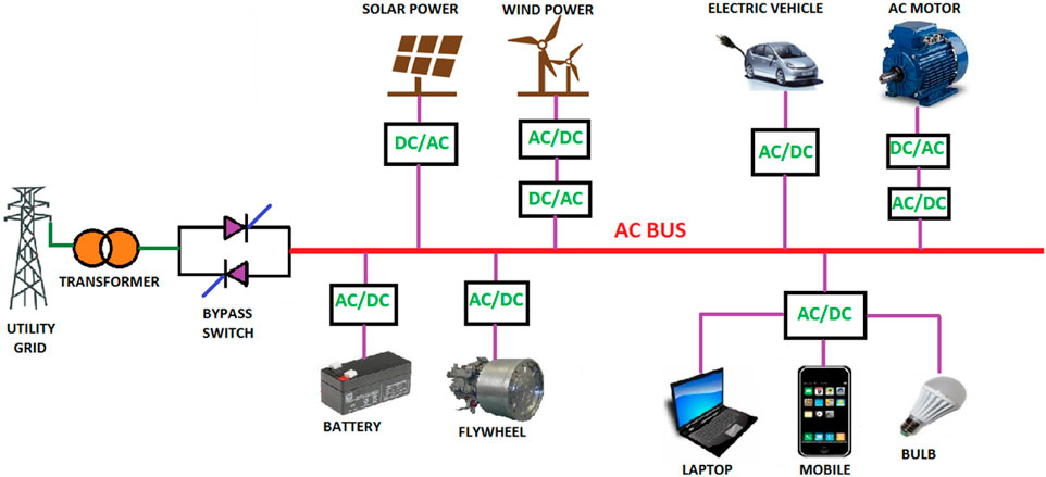
Figure 1. Layout of AC microgrid.
2.1.2 DC microgrids
In this type of microgrid, the bus voltage is DC, leading to its designation as a DC microgrid (Kumar et al., 2017). In residential and commercial applications, such as computers, battery chargers, and highly efficient lighting systems, DC power is required. Consequently, these appliances necessitate AC-DC conversion to be compatible with the conventional AC supply available. The multiple conversion stages involved can reduce the reliability and overall system efficiency. However, these challenges can be mitigated by utilizing highly efficient DC-DC converters, offering the possibility of directly connecting devices to the DC grid. In a DC microgrid, renewable energy sources and power electronics can be connected effectively and efficiently to loads by selecting a suitable voltage level, ensuring fewer conversion stages, as depicted in Figure 2 (Kumar et al., 2017).
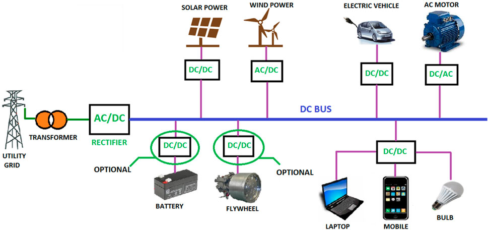
Figure 2. Layout of DC microgrid.
2.1.3 Hybrid microgrids
Two different types of buses are available in this form of microgrid; one type provides AC voltages, while the other type provides DC voltages (Kumar et al., 2017). When both AC and DC type generation from renewable energy sources are available, as in Figure 3 (Kumar et al., 2017), this setup works best for the application.
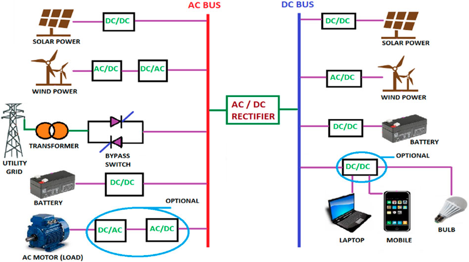
Figure 3. Layout of Hybrid microgrid.
2.1.4 Strengths/weaknesses of DC/AC microgrid system
Table 1 higlights some ke strength of DC microgrids amon the weakness of AC microgrids (Rangarajan et al., 2023).
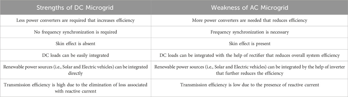
Table 1. DC versus AC microgrid.
2.2 Development of DC systems and microgrids
This section deals with development, evolution of microgrid and DC system.
2.2.1 Evolution of DC systems
The battle between Westinghouse and Tesla vs Edison and J.P. Morgan regarding “What Comes Next” is referred to as the “War of the Century (Blasi, 2013). Both sides are on the point of realizing how much the future infrastructure of electricity would be worth financially (Blasi, 2013).
In the late 18th century, in 1880, the director of the Edison Illuminating Company, Thomas Edison, developed a small power plant in Pearl Street Station to supply customers with DC power to operate low-voltage DC-powered lamps (Xu and Cheng, 2011). The power of that plant was distributed in three lines (i.e., a bipolar distribution) with +110, 0, and −110 voltage levels (Seyedmahmoudian et al., 2015) The main drawback of that power was that the voltage drop is high in power lines; therefore, power transmission towards remote areas and other residential neighborhoods away from the main generating station was not a suitable choice. There was no voltage transformation; the small plant and loads were only incandescent lamps and DC motors (Seyedmahmoudian et al., 2015).
Nikola Tesla, in 1886, introduced the concept of alternating current by utilizing transformers to change the voltage levels. The debate strengthened in 1887, when Nikola Tesla registered several patents in the United States (Seyedmahmoudian et al., 2015). Patents were based on the AC Distribution Scheme and supported by Westinghouse Electric and Manufacturing Company. The findings of Tesla widely affected the superiority of the AC system in the BATTLE OF CURRENTS. In 1893, Westinghouse won a contract to build a hydroelectric dam to harness the power of Nigeria Falls and transmit it to Buffalo, New York. The project was finished on 16 November 1896, and AC Power began to power industries in Buffalo. This milestone marked the decline of DC in the United States by providing a successful experience for future worldwide power transmission and distribution projects (Sulzberger, 2003; Moser, 2008).
Edison exerted considerable efforts to increase the efficiency of the DC system and reduce line loss in the 1880s by using a series of motor generators to create the HVDC system (Seyedmahmoudian et al., 2015). Such a model was capable of power transmission over longer distances. But HVDC was never adapted because of maintenance and high installation costs, almost for a century (Seyedmahmoudian et al., 2015).
After the invention of the transistor in 1947 by John Bardeen, the electronic revolution started. The invention of high-voltage power electronic devices in particular has made a comeback of DC possible (Van Willigenburg et al., 2022), when there was an advancement in the power electronics field, DC-DC converters (i.e., Buck, Boost, and Buck-Boost) were introduced. These were able to transform DC power to different voltage levels as per the desired appliance requirement (Gelani et al., 2021). This was the time when supremacy was enjoyed by DC over AC. DC power has started in the field of generation by utilizing renewable energy sources, i.e., solar, fuel cells, etc. Generated DC power is transmitted over longer distances through HVDC transmission (Gelani et al., 2021).
2.2.2 Development of microgrids
Microgrids were initially introduced in 2001 by Bob Lasseter, who led the IEEE PES WM Panel, as evidenced by his conference paper (Glinkowski et al., 2017) and the CERTS Report (Kondoleon et al., 2003) in 2002. Currently, major countries worldwide, including the United States, the European Union, Japan, and China, have conducted research on microgrids.
The Consortium of Electric Reliability Technology Solutions (CERTS) in the United States is a renowned institution for Micro Grid Research (Barnes et al., 2007). It introduced the pioneering concept of Micro Grid in a White Paper known as the “Micro Grid Concept,” prepared for the California Energy Commission and the DOE. CERTS Micro Grid developed the concept of peer-to-peer with plug-and-play strategies, successfully demonstrated in a test bed with American Electric Power (LI et al., 2014). Northern Power Systems (NPS) implemented a Micro Grid installation in MAD RIVER, Waitsfield, Vermont (Barnes et al., 2007), featuring a central Microgrid Controller (Northern Power Systems, 2005). In the Boston Bar system of British Columbia Hydro, a single large generating station is effectively employed (Barnes et al., 2007) to control the net subsystem behavior using Micro Grid Control. The General Electric Corporation is in the process of field trials for its Microgrid Concept (Barnes et al., 2007) and is actively working on developing the Micro Grid Energy Management System.
Major projects have been carried out in the European Union on microgrids, including the MicroGrid Project and More MicroGrid Project, in order to take advantage of renewable energy sources and enhance their use for microgrid improvement (LI et al., 2014). The Micro Grid project is linked to concepts, challenges, and laboratory tests, while the More Micro Grid Project has designed seven pilot installations, with the first distributed-generated application also in Micro Grids on the island of Kythnos (Vasilakis et al., 2020). Kythnos Microgrid was constructed on Kythnos Island (LI et al., 2014), providing electricity to 12 houses in a small valley (Schwaegerl, 2006). A low-voltage microgrid (CESI Test Facility) in Milan was developed, which is synchronized with a medium-voltage grid for the testing of distributed generation technologies (Barnes et al., 2007; LI et al., 2014). This system is used as part of the More Microgrid Project.
The Labein Research Institute in Spain has put together a test system for distributed generation and microgrid research (the Labein Microgrid) (Barnes et al., 2007). The Portuguese Electricity Utility (EDP Feeder) is in the process of upgrading the far end section of a small commercial radial feeder in order to undertake microgrid studies (Barnes et al., 2007). Together with EMforce and Germanos, Continuon upgraded a holiday park it runs in the Neitherlands into a microgrid (Continuon Holiday Park microgrid) (Barnes et al., 2007). The first EC Micro Grid Project used the Demotec facility at ISET in Kassel to develop methodologies for the control of distributed generation in microgrids (Barnes et al., 2007). In Mannheim, Germany, the substation network connected to the MVV headquarters has been identified by MVV as a site to investigate microgrids (Barnes et al., 2007). The Shimizu Corporation has built both a pilot and large-scale microgrid at its research labs in Tokyo (Shimizu Extended Microgrid) (Barnes et al., 2007). The Regional Power Grid with Renewable Energy Resources Project, an initiative of the New Energy and Industrial Technology Development Organizations (NEDO), has commenced three demonstrations (Zhou et al., 2015).
• Hachinohe System; this project is a collaboration between Hachinohe City, the Mitsubishi Research Institute, and Mitsubishi Electric (Barnes et al., 2007; Marnay and Firestone, 2007). This system contains PV, wind turbines, battery energy storage, and three large gas engines fed by sewage and waste gas.
• Sendai Micro Grid was implemented by the New Energy and Industrial Technology Development Organization between 2004 and 2008 (LI et al., 2014), based on PV generation, fuel cells, and two gas engines. This microgrid project showed its effectiveness, especially in the destructive earthquake in Tohoku District on 11 March 2011. (LI et al., 2014; Morozumi, 2006).
• In 2006, Tsinghua University began to explore and research the field of microgrids by using the hardware of the State Key Lab and building an experimental platform for microgrids with renewable energy generation, energy storage devices, and loads (Zhou et al., 2015).
• In 2007, the Photovoltaic Engineering Research Center of Hefei University of Technology built a small power grid by using solar and wind power, which can work as an independent microgrid system (Zhou et al., 2015).
• The Chinese Academy of Sciences built a 200 kVA microgrid test system and analyzed the system for steady state and dynamic state (Zhou et al., 2015).
2.3 DC microgrids
The concept of DC microgrids, integrated with renewable energy sources, has gained significant importance due to advancements in modern power electronics and an increasing awareness of environmentally friendly power generation, specifically in the form of DC (e.g., solar, fuel cell, super capacitor, and battery storage) (Hossain et al., 2019). These microgrids exhibit enhanced efficiency by directly powering DC loads, eliminating the need for multiple conversion stages and distinguishing them from traditional AC microgrids. Furthermore, the integration of the mentioned renewable sources seamlessly occurs without requiring extra conversion processes. Commercial applications, emphasizing low voltage DC distribution schemes like Electric Vehicles, Telecommunication Systems, and Shipboard Power Systems, are thoroughly explored in (Ciezki and Ashton, 2000; Nilsson and Sannino, 2004; Salomonsson and Sannino, 2007; Elsayed et al., 2015). The expansion of distributed energy sources like solar and wind, and their integration in DC microgrid requires stable operation and proper protection mechanisms (Dashtdar et al., 2022).
Various papers have shown that DC micromrid plays an effective role in solving operational issues on the main grid (Justo et al., 2013). In (Mohamed et al., 2012), a DC microgrid, including PV generation and battery storage system, was used to mitigate heavy nonlinear loads. Experimental evidence presented in (Mohamed et al., 2013) demonstrates that DC microgrids can be widely employed for voltage support by utilizing the capability to inject reactive power as an ancillary service. In (Kakigano et al., 2010), some authors demonstrated that reducing the conversion stages of inverters in DC microgrids between DC load and DC output makes the system more efficient.
2.4 Efficiency comparison of DC microgrid with AC microgrid
As per the discussion in previous sections, it has been observed that with multiple conversion stages, the efficiency of the system is reduced as compared to single conversion stages. In (Manandhar et al., 2016), the comparative analysis of low-voltage DC and low-voltage AC systems is analyzed in terms of conversion efficiency.
2.4.1 Low voltage AC distribution system
Commonly, most devices used in homes, such as laptops and mobiles, operate on DC power for charging. However, the supply available in homes is typically AC. Consequently, there is a need for a two-step conversion process–first from AC to DC and then again from DC to a compatible form for the appliance (Manandhar et al., 2016), as illustrated in Figure 4. This dual conversion process leads to an overall reduction in efficiency. As noted in (Sulzberger, 2003), rectifiers, a crucial component in this conversion, are observed to have higher losses.
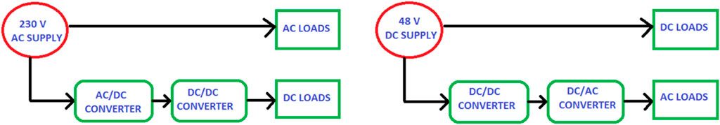
Figure 4. Low voltage AC vs. low voltage DC distribution system.
2.4.2 Low voltage DC distribution system
The Low Voltage distribution system is explored and operating at 48V DC. This system proves advantageous for appliances that necessitate DC power for their operation. These appliances can be connected directly or through a DC-DC converter in case the voltage levels are mismatched (Sulzberger, 2003), as depicted in Figure 4 above. However, household appliances typically run on AC power. If power is generated using a photovoltaic system, which produces DC, it must be converted to AC using an inverter. As noted in (Sulzberger, 2003), it has been observed that an inverter incurs fewer losses compared to a rectifier. In order to compute the efficiencies of both the LVAC and LVDC distribution systems, the networks are simulated in PSCAD software (Manandhar et al., 2016). Based on the input and output power of each conversion, the efficiencies at each stage comprises of rectifier and chopper for LVAC system, and for LVDC system it comprises of chopper and inverter. It has been observed from PSCAD simulation results of (Manandhar et al., 2016) that the total conversion efficiency of the LVAC system consists of rectifier and chopper efficiency. So the overall conversion efficiency of the LVAC system according to (Gwon et al., 2014) is 78.24% and for the LVDC system the efficiency is 84.6%.
In (Gwon et al., 2014), an LVDC distribution system is simulated using EMTP software with a DC voltage level of 380 V at the DC bus. Both the AC load and DC load models have been connected through a DC bus as shown in Figure 5, and power across each conversion stage is obtained.
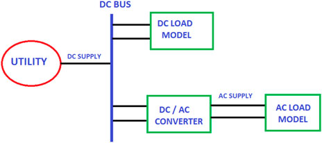
Figure 5. LVDC distribution system.
In this LVDC system, the utility is assumed to be DC-like generation from photovoltaic modules. Further it is divided in AC and DC load models.
• AC load model composed of a rectifier, buck converter, and constant power load, which is basically DC load. Here, AC input comes from an inverter (Gwon et al., 2014)
• DC load model composed of a buck converter and constant power load, which is basically DC load. Here, DC input comes from the DC bus, as shown in (Gwon et al., 2014)
Considering the model of an AC load with two power conversion stages, The efficiency is calculated at each conversion stage (Gwon et al., 2014), including 75% rectifier efficiency and 91% inverter efficiency. This yields an overall efficiency of 68.25%.
Considering the model of DC load, there is one conversion stage. So the total efficiency is basically the efficiency chopper. The total DC load model efficiency is 90.44%. It has been observed from simulation results of (Gwon et al., 2014) that the conversion efficiency of the AC load model is reduced. The AC load model contain three power converters, i.e., inverter, rectifier and a buck converter. Due to these multiple conversions, the LVDC system is not suitable for AC load model. Whereas, in the DC load model, it only needs one power conditioner, i.e., buck converter, therefore it is reliable to utilize to DC load model with LVDC Distribution System.
In (Anam et al., 2018), AC Microgrid and DC Microgrid are compared for efficiency by utilizing solar wind hybrid renewable energy systems. Two systems are simulated, one for AC System and the other for DC system, which is basically the extension of the AC System. Figure 6 (Anam et al., 2018) show the renewable sources are connected to common AC bus, which is supplied by wind turbine with a 5 KW rating and solar panels with a 5.3 KW rating. The wind turbine is directly connected with AC Bus, while solar panel is connected through an inverter towards AC bus. In the AC system, the load is static load with an 8 KW rating; similarly in DC system, two buses have been created AC and DC by utilizing rectifier, and static DC load is used with an 8 KW rating. Power flow analysis is performed, which yields voltage levels and branch losses for both buses as a function of the equal load on both buses. It has been observed that the voltage drop in the AC bus somehow increase compared to the DC bus, and the AC system has increased losses as compared to the DC system.
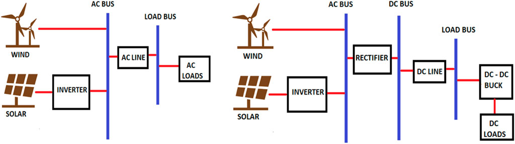
Figure 6. AC microgrid with solar and wind along with extension for DC system.
In (Justo et al., 2013) the AC and DC distribution Line has been compared in terms of efficiency by considering the parameters such as resistance and reactance. It has been observed from the comparative analysis performed in (Justo et al., 2013) that in terms of power transfer capability, the DC line has fewer losses as compared to the AC line, hence the overall efficiency of the DC system is improved as compared to the AC system.
In (Sabry et al., 2020), the compatibility of household appliances that are powered with AC and DC has been analyzed. An energy measurement (Sabry et al., 2020) has been performed to validate the power profile of inverter driven air conditioner under operating conditions, a normal AC power supply and a proposed 310 V DC supply as depicted in Figure 7. The results show that such an air conditioner consumes a daily power up to 11.466 kW h, which contains DC to AC (inverter) for the DC source-inverter load configuration, but when such air conditioners are directly coupled to the DC source-load configuration, the daily power consumption up to 9.850 kW h has been observed.
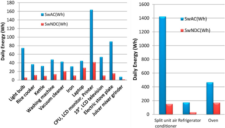
Figure 7. Daily energy saving with traditional DC Source Inverter appliances and proposed DC source appliance.
To show the efficiency of the proposed (DC Source Appliances) configuration with conventional (DC Source Inverter Appliances) based on energy savings, as shown in Figure 7 that the proposed DC bus is efficient due to somehow less energy consumption than conventional AC. Therefore, great reduction in power consumption has been obtained for the DC system, which makes it more robust and efficient.
In (Saputra et al., 2019), the comparative analysis of hybrids on grid A photovoltaic system is performed by utilizing AC and DC grids, which supply households. The analysis was performed by utilizing the efficiency of power converters in order to compute the power loss in each converter. Utilization of DC grid ultimately reduces the AC Conversion losses to DC and vice versa. It can be observed by considering the efficiency of AC and DC grids that which system is robust and efficient with photovoltaic generation and can be synchronized with main utility grid. As observed the efficiency of AC grid yields efficiency of 90.13% while with DC grid the efficiency has been obtained up to 93.20%. So from this analysis, it has been depicted that the performance of the DC grid is better under load change as compared to the AC grid system.
The study carried out in (Jinchi et al., 2019) focuses on comparing the energy efficiency of AC and DC microgrids. the authors explore three different power supply modes. They analyze the distribution scenarios, including components, loads, and photovoltaic power generation. The results reveal that DC power distribution has advantages over AC power distribution, with an overall efficiency improvement of 6.5%–7.9% The authors in (Thakur, 2020) provides valuable insights into the stability analysis of a DC microgrid connected with renewable energy sources. The authors in (Sayed et al., 2019), investigated the six terminal DC microgrid in simulation and applied droop control methods. The proposed method has been well investigated and tested in simulation environment at multiple scenarios, there is need that the system to be analyzed during symmetrical and asymmetrical faults. In (Xiong and Yang, 2020), the paper presents a photovoltaic-based DC microgrid system designed with a control strategy for optimizing power utilization and ensuring stability based on discrete time mapping model for stability analysis, The proposed method has increased computational burden. In (Saha et al., 2019), the stand-alone solar micro-grid system was designed and simulated. The system components, including the single-phase full bridge DC to AC inverter, DC to DC boost converters, battery discharge condition, and backup condition, were analyzed through simulation. Different cases of the stand-alone solar micro-grid system were analyzed through simulation to verify the validity of the models. But there is a lack in hardware prototype and efficiency comparisons. In (El-Shahat and Sumaiya, 2019), the author presents a standalone solar PV system with a DC microgrid, including components like boost DC/DC converter, MPPT techniques, bidirectional DC/DC converter, DC-AC inverter, and batteries. Their main target was comparing MMPT techniques, their system lacks efficiency comparison and reasons to promote DC systems for remote areas. In (Basantes et al., 2023), the authors investigated the islanded DC microgrid based on MPC technique having multiple complex current and voltage loop to maintains stability of the system, but multiple load scenarios and different faults scenarios needs to be analyzed.
2.5 Research gaps and scope of this work
In (Manandhar et al., 2016), an evaluation comparing the efficiency of the existing LVAC system and the prospective LVDC distribution system has been conducted, focusing on converters’ conversion efficiency. However, there is potential for broader application by incorporating renewable energy sources (RES) and energy storage systems (ESS) into the DC system. This integration could enhance overall efficiency, particularly when comparing AC and DC microgrids. In (Gwon et al., 2014), researchers delved into power efficiency for AC and DC loads in an LVDC distribution system. It is crucial to note that conclusively asserting LVDC’s superiority over the LVAC system may be insufficient, as adopting LVDC as a new distribution system would necessitate replacing existing AC loads with DC loads to achieve efficiency improvements. In (Anam et al., 2018), the focus has been on software implementation alone, emphasizing the need for hardware implementation to enhance accuracy. In (Thakur, 2020), there is an vacuum for the prototype development that yields how efficient the system is.
This study aims to address certain gaps identified in prior research. Initially, a hardware prototype of a scaled-down 4-terminal DC microgrid was developed to analyze the efficiency of the DC system in comparison to the conventional AC system. Subsequently, the scaled prototype was expanded to a six-terminal DC microgrid within a simulation environment. Various aspects were explored in the simulation model, including testing the steady-state stability of the DC microgrid by integrating multiple renewable energy sources and operating loads. An extension was then performed to analyze the system under different loads, such as motors. Finally, the system underwent testing under different fault conditions, encompassing both symmetrical and asymmetrical faults.
3 Methodology
3.1 Hardware implementation
The physical prototype of a DC microgrid consists of photovoltaic panels, rechargeable batteries, an MPPT charge controller, and DC loads. The specific voltage level for DC microgrids used for rural electrification is selected as 60 V (Richard et al., 2022). Figures 8, 9 shows proposed and conventional DC and AC systems, respectively.
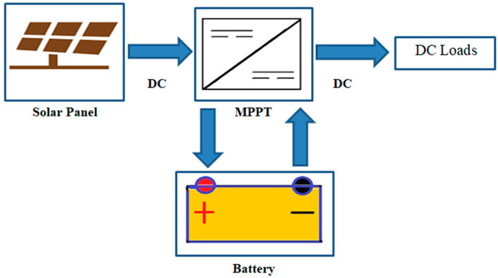
Figure 8. Proposed DC system.

Figure 9. Conventional AC system.
3.1.1 Solar panel specifications
The STP250-20/Wd solar panel has been used in this work. Its specifications are mentioned in Table 2. For the analysis, four solar modules have been utilized, arranged in a series-parallel combination.
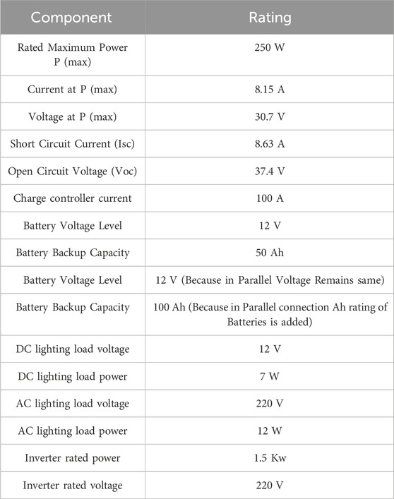
Table 2. Hardware prototype ratings.
The first string contains two solar panels connected in series, yielding 30.7 V + 30.7 V = 61.4 V and 8.15 A. The second string has the same configuration as the first string, but it is connected in parallel with the first string this increases the current rating to 8.15A+ 8.15 A = 16.30 A. The total power generation is therefore 61.4 V * 16.30 A = 1000.68 W = 1 kW.
3.1.2 Battery specifications
Absorbed Glass Mat (AGM) Type battery has been utilized in hardware prototype. Two batteries are utilized in parallel combination; single battery rating and overall rating of battery bank is described in Table 2.
3.1.3 MPPT charge controller
The purpose of utilizing the MPPT charge controller is to operate the photovoltaic panels at their maximum power point to obtain maximum power generation. The power generation through solar is greater than the voltage level of the battery bank; therefore, the MPPT charge controller converts the excessive solar voltage into amperage for fast charging of batteries.
3.1.4 Selection of loads
For analysis and comparison of the proposed DC system with the existing AC system, DC lighting loads with a 12 V rating have been utilized in the proposed system.
3.2 Software implementation
The physical prototype layout of a 4-terminal DC microgrid has been extended to six terminals (Belkhier and Oubelaid, 2024; Al-Ismail, 2021; Ali et al., 2021; Al sumarmad et al., 2023) in the simulation environment, as shown in Figure 10 above. The ratings of software model has been enlisted in Table 3.
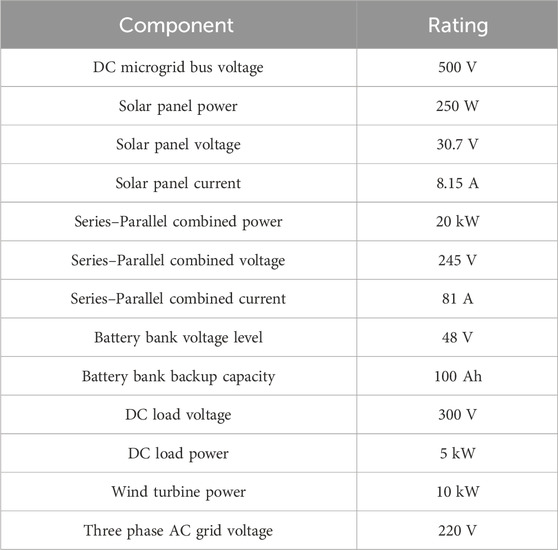
Table 3. Simulation model ratings.
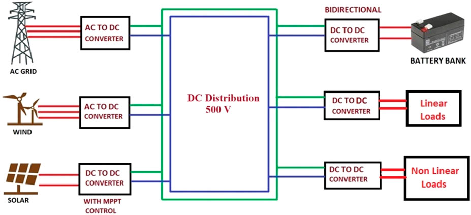
Figure 10. Six terminal DC microgrid Layout.
3.2.1 Solar side
The photovoltaic module utilized in this simulation is the same as that of the hardware prototype, with a slight change in the voltage rating of the DC microgrid that has been selected as 500 V DC (Ardriani et al., 2021), and the power rating has been extended to 20 kW (Elmorshedy et al., 2023).
Initially, in one string of PV systems, eight modules are utilized in series, which yields 30.7 V * 8 = 245.6 V DC and 8.15 A. Through this, only a 2 kW system is obtained. By utilizing a series combination of strings, 90 other strings are created, and a total of ten strings are utilized in parallel, which yields 245.6 V DC and 81.5 A. Overall power is now 245.6 V * 81.5 A = 20,016.4 W = 20.01 kW. In order to achieve 500 V DC, a boost converter is utilized with an MPPT algorithm. The preferred MPPT algorithm utilized in simulation is the incremental conductance method (Mishra and Tiwari, 2021).
3.2.2 Wind side
The wind turbine integrated with DC Microgrid possesses a power rating of 10 kW (Aloo et al., 2023; Khodabakhsh et al., 2020). Initially, wind turbines provide AC power because, in simulation, a permanent magnet synchronous generator is used. So to convert AC power into DC power, the controller is designed for rectifier mode operation that converts three-phase AC voltages into proper DC voltage up to 500 V DC.
3.2.3 Battery bank
The battery bank is added inside the system to maintain the reliability and stability of the system. The main purpose is to maintain the power flow, stabilize the voltage, and generate maximum power (Aemro et al., 2020).
3.2.4 DC load
The DC load targeted in the simulation environment is linear and nonlinear. The voltage rating of a DC resistive load is 300 V; therefore, a buck converter is designed to produce 300 V from 500 V DC. And in nonlinear loads, a DC motor is added; the same voltage rating of the buck converter is used.
3.2.5 AC grid
The three-phase AC grid is also coupled to the proposed DC microgrid. Initially, AC voltages are obtained, but in order to integrate them with the DC microgrid, AC voltages are needed to be converted to DC by using a converter operating in rectifier mode.
3.3 Data collection procedure
It involves fours steps given as follows.
3.3.1 Defining metrics
This includes specific performance metrics such as efficiency, stability, fault recovery time and reliability
3.3.2 Instrument setup
This includes the proper installing of precise measuring instrument in both DC and AC mcrogrid systems. Make sure that both system are settled up the same way and check each system individually
3.3.3 Data collection
Performed multiple testing sessions under changing load and record data continuously
3.3.4 Analyze data
Calculated efficiency and validated the results by observing the stability
3.4 Proportional-integral controller approach
In order to manage real time tuning of gains, instead of simple PI, in this research adaptive PI controller is utilized that is based on scheduling of gain, therefore this possess dynamic gain adjustments.
Robust Droop Control Management Using PI Approach.
Voltage regulation at load terminals: scenario for operating motor as a load.
Separate PI controllers are installed at each DC load terminal to ensure voltage stability. If the voltage at the load terminals deviates from the set point, the respective controllers adjust the output voltage of the DC-DC converters to maintain optimal voltage levels. For instance as seen in Figure 19, when the motor starts at 1.5 s the controller tries to maintain stable voltage level across the load that is needed to be constant 300V.
3.5 Comparitive analysis with other available controllers
The detailed comparison of the proposed PI controller approach with other relevant control strategies (i.e., PID and MPC (Joshal and Gupta, 2023)) commonly used in DC microgrids. Table 4 summarizes the key features of each approach.
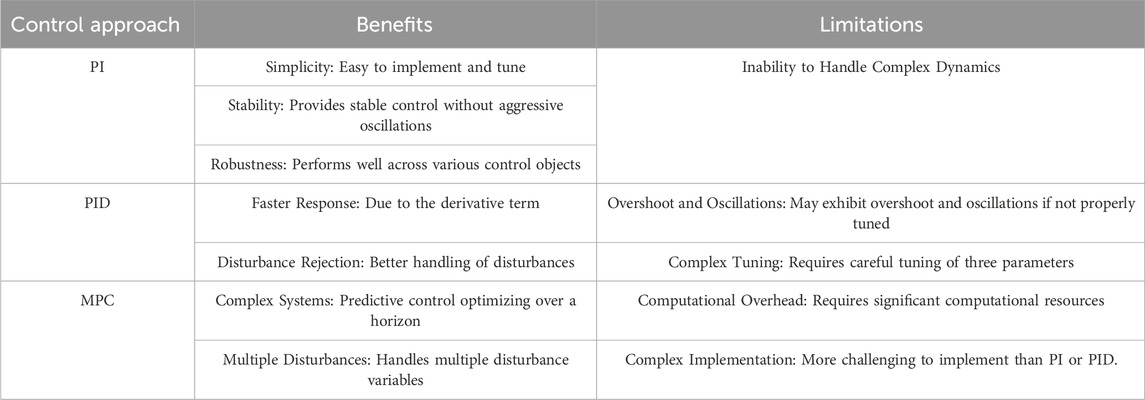
Table 4. Comparitive analysis of PI, PID and MPC for designed DC microgrid.
3.5.1 Justification for PI controller
While newer approaches exist, the PI controller (Vijayan et al., 2022) remains relevant for several reasons.
⁃ Robustness: The PI controller is less sensitive to parameter variations, making it suitable for practical implementations.
⁃ Stability: In many real-world scenarios, stability and steady-state accuracy are critical, and the PI controller excels in these aspects.
⁃ Simplicity: For small-scale DC microgrids or applications with limited computational resources, the PI controller strikes a balance between performance and simplicity.
3.5.2 Uncertainty handling
The proposed PI controller incorporates uncertainty handling through dynamic gain adjustment. The scenario has been examined in the way that owing to the observance in Figure 19, when motor starts the inner controller tried to maintain and stabilize the load voltage that is 300 V, but overall the bus voltage experiences a jerk at start of motor, that has been vanished and stabilized. This shows that the system has capability of uncertainty handling.
4 Results and simulations
This section is divided into four sub sections, including performance metrics, hardware and software-based system results along with the overall computational complexity of control approach respectively.
4.1 Performance metrics
The performance metrics of proposed hardware system based on.
(1) Overall system efficiency
It refers to the calculation of both DC and AC microgrid system efficiency which is the ratio of utilized power over available electrical power. It is expressed in percentage. After individual system efficiency calculation compare the results of both systems.
(2) Energy conversion
This refers to the individual conversion process for both systems such as DC-AC conversion in AC microgrid while DC-DC conversion in DC microgrid.
While the performance metrics of simulated model based on.
(1) Voltage stability
The ability of proposed DC microgrid to maintain stable DC voltage level across its terminal under varying load conditions. Stable DC voltage yields robustness for maintaining dedicated operating condition.
(2) Response time
The speed at which DC microgrid system reacts to the changing load or environmental condition is crucial for maintaining stability and efficiency in dynamic operating conditions.
4.2 Hardware results
4.2.1 Designed DC system
As most of the DC appliances are operated on a standard DC voltage level of 12 V DC, similarly, the lighting load installed for this purpose is also based on a 12 V DC supply, which is given by the MPPT Charge Regulator to DC Loads. Figures 11, 12 shows solar voltage and current and battery voltage and current, respectively.

Figure 11. Solar voltage and current.

Figure 12. Battery voltage and load current.
Total wattage rating of DC lighting loads analyzed is
The input voltage from solar is measured as 61.9 V.
4.2.2 Conventional AC system
In order to measure the efficiency of a conventional AC system, the AC lighting loads have been operated using an inverter that is supplied by a constant DC source.
Initially battery has been connected with inverter the input voltage of battery is observed as 12.19 V as mentioned in Figure 13.

Figure 13. Battery voltage and current.
Figure 14 below shows inverter voltage and load current that is noted using clamp meter.
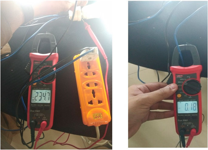
Figure 14. Inverter voltage and load current.
4.2.3 Efficiency calculation of designed DC system
4.2.4 Efficiency calculation of conventional AC system
4.3 Software results
4.3.1 Results during steady state conditions
Figure 15 gives the solar voltage round about 245 V and the current of 81 A. Overall the total power obtained in simulation from solar side is 20 kW. This suggests that designed DC system is capable of providing a substantial amount of electrical energy which could potentially meet the demand of various applications. The generated power may be adequate for powering residential, commercial and industrial loads.
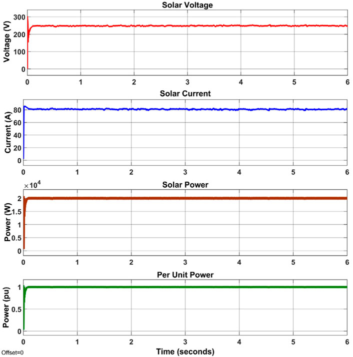
Figure 15. Simulation results of solar side.
Figure 16 shows the wind turbine that is designed to generate a constant output power of 10 kW, which significantly indicates that it has great potential to contribute significant electrical energy to DC microgrid. Initially there is a peak transient that last up to 0.1 s.
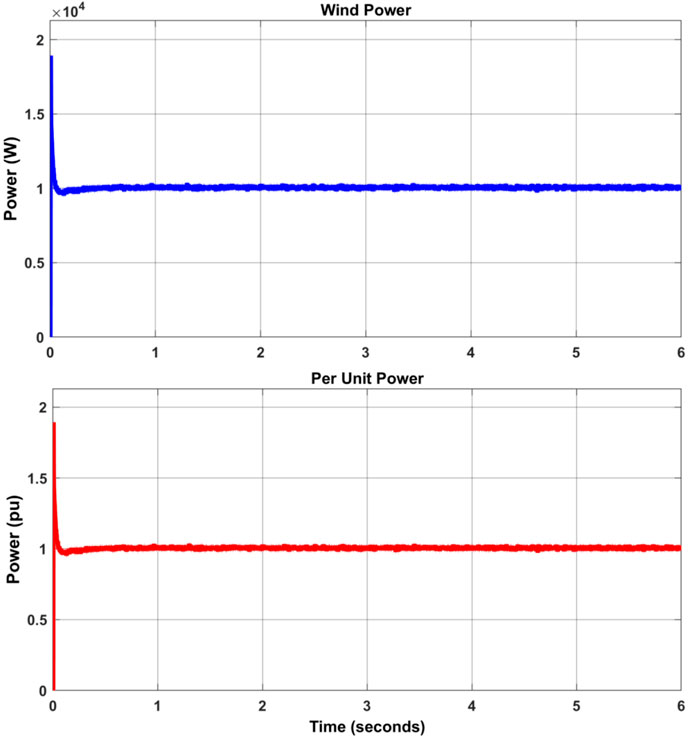
Figure 16. Simulation results of wind power.
In Figure 17, Stable DC voltage and current indicates that the controller has ability to regulate voltage and current within desired limits ensuring consistent performance of the connected load. Scaling the power rating of the load in per unit allows for easier analysis and compatibility assessment within the DC microgrid.

Figure 17. Simulation results for 5 kW DC resistive load.
Figure 18 shows the simulation results that demonstrate stable DC voltages of up to 500 V at each terminal. Fewer transients and a shorter settling time are observed in the voltage behavior. This stability is essential for maintaining reliable power distribution and operation. Furthermore, the reduction in transients and settling time indicates improved system performance and dynamic response, contributing to the overall efficiency and effectiveness of the microgrid.
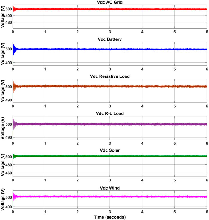
Figure 18. Simulation results of DC bus Voltages.
4.3.2 Analysis of results by adding motor as a load
The addition of the motor load in Figure 19 initially induces a transient voltage perturbation, commonly termed as a “jerk.” However, over time, this disturbance dissipates, leading to a rapid stabilization of the bus voltage. This mitigation of transient effects suggests enhanced system dynamics and control mechanisms, crucial for optimizing the microgrid’s stability and operational efficiency.

Figure 19. Simulation results during operating Motor as a load.
4.3.3 Fault scenarios
Following are the fault scenarios observed in this work.
4.3.3.1 Line to line to ground (asymmetrical) fault
As shown in Figure 20, initially the bus is providing 500 V DC, but during the L-L-G fault at 0.6 s–1 s, the bus voltage turns to 0. Stability returns at 1.045 s post fault clearance, swiftly restores the DC bus voltage. The fast recovery of the bus voltage underscores the efficacy of fault management mechanism which is essential for sustaining the reliability and stability in DC microgrid.

Figure 20. Simulation results during (L-L-G) fault.
4.3.3.2 Line to line to line (symmetrical) fault
As shown in Figure 21, initially the bus is providing 500 V DC, but during the L-L-L fault at 0.8 s–1.3 s, the bus voltage turns to 0. The system gets stable in 1.35 s when the fault is cleared and bus voltage is recovered.
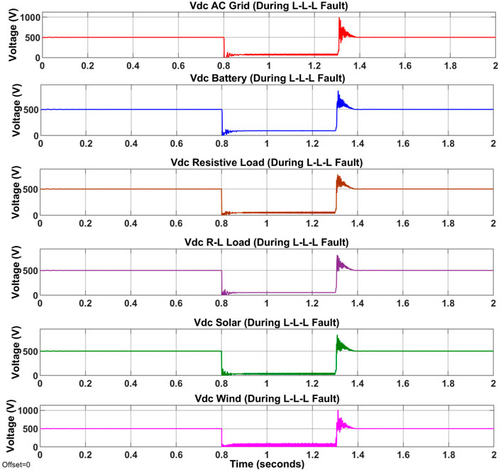
Figure 21. Simulation results during (L-L-L) fault.
4.4 Computational complexity
The computational complexity of the proposed approach using PI approach is generally observed as low because of the following reasons.
• The calculations involved in overall model are based on proportional and integral terms. They need arithmetic operations including addition, multiplication as well as integration.
• It does not require extensive memory resources or complex algorithms.
• The executing time of the PI controller remains relatively constant regardless of the system operating conditions. Relatively fixed time behavior simplified timing analysis and ensures predictable performance in real time control systems.
• PI controller is normally implemented using single hardware components or software logic, further reducing computational complexity of the designed system.
5 Conclusion and future perspective
This paper provides a comprehensive overview of microgrids. DC microgrids have become a natural development resulting from technological, regulatory, and market advancements in the quest for localized and reliable power. However, ongoing efforts are directed towards the development of DC loads and appliances, aiming to replace conventional AC-powered appliances with DC.
The findings of this research indicate a noteworthy enhancement in the efficiency of the DC system, ap-proximately 15.5%, when juxtaposed with the conventional AC system. The principal rationale identified in this study for the heightened efficiency in DC systems resides in the utilization of converters known as choppers (DC-DC conversion). This mechanism ensures consistency in both input and output power, maintaining the DC form, thereby necessitating fewer conversions. Conversely, in AC systems, particularly those reliant on solar generation, an inverter (DC-AC conversion) is requisite. In this inversion process, the input power is DC while the output power is AC, leading to form losses within the inverter and subsequently diminishing the overall efficiency of inverter-based DC/AC microgrids. This paper thoroughly explores how efficient DC microgrids are compared to AC microgrids. The conclusion is that, in today’s power systems, DC microgrids are recognized as more efficient. However, it is important to recognize existing challenges that need attention to make sure microgrids work reliably and robustly.
There are multiple avenues for future research to implement a more efficient and scalable DC microgrid. This prototype of a four-terminal DC microgrid in this research is designed for operating DC lighting loads. The prototype can be extended to operate other types of loads and scaled up beyond one laboratory for lighting loads. The application may also be expanded by incorporating fuel cells and supercapacitors, integrating them into the designed prototype.
The simulation-based model of a six-terminal DC microgrid is designed for operating DC resistive load and motor. The application may be extended by adding an inverter for AC loads, and harmonic analysis can be performed. Electric vehicles can be modeled and added to the DC microgrid for the extension of research. DC bus signaling can be incorporated to obtain multiple DC bus voltages. This model is analyzed in islanded mode of operation; the research can be extended to analyze grid-connected mode. AC fault recovery from the wind side has been conducted in this research; future scopes provide opportunities for investigating converter side faults and DC fault recovery from the solar side.
6 Novel contributions and advantages of proposed work
Efficiency Improvement: This research achieved a 15% efficiency gain in 4-terminal DC microgrid compared to an inverter-based AC microgrid. This improvement is significant and directly impacts real-world applications.
Stability and Fault Recovery: MATLAB model in this research for the six-terminal DC microgrid demonstrates robust performance under steady-state conditions and fault recovery scenarios. Fault from the system has been recovered within 80 ms.
Therefore, the primary purpose of this work is to contribute to the advancement of microgrid technology by.
• Enhancing energy efficiency through DC microgrids.
• Ensuring reliable operation under steady-state conditions.
• Demonstrating robust fault recovery capabilities.
These contributions advance the field by providing practical solutions for DC microgrid design and operation.
Data availability statement
The raw data supporting the conclusion of this article will be made available by the authors, without undue reservation.
Author contributions
DM: Investigation, Methodology, Software, Writing–original draft. KA: Conceptualization, Methodology, Project administration, Supervision, Writing–review and editing. AM: Data curation, Resources, Supervision, Writing–review and editing. JA: Data curation, Formal Analysis, Validation, Writing–original draft. JB: Project administration, Validation, Writing–original draft. MA: Funding acquisition, Project administration, Validation, Writing–review and editing. AB: Data curation, Writing–original draft. MK: Data curation, Funding acquisition, Resources, Writing–review and editing.
Funding
The author(s) declare that no financial support was received for the research, authorship, and/or publication of this article.
Acknowledgments
Authors acknowledge the Researchers Supporting Project number (RSP2024R467), King Saud University, Riyadh, Saudi Arabia.
Conflict of interest
Author AB was employed by Tier Energy Ltd.
The remaining authors declare that the research was conducted in the absence of any commercial or financial relationships that could be construed as a potential conflict of interest.
Publisher’s note
All claims expressed in this article are solely those of the authors and do not necessarily represent those of their affiliated organizations, or those of the publisher, the editors and the reviewers. Any product that may be evaluated in this article, or claim that may be made by its manufacturer, is not guaranteed or endorsed by the publisher.
References
Aemro, Y. B., Moura, P., and De Almeida, A. T. (2020). Design and modeling of a standalone Dc-Microgrid for off-grid schools in rural areas of developing countries. Energies 13 (23), 6379. doi:10.3390/en13236379
Ali, S., Zheng, Z., Aillerie, M., Sawicki, J. P., Péra, M. C., and Hissel, D. (2021). A review of dc microgrid energy management systems dedicated to residential applications. Energies 14 (14), 4308–4326. doi:10.3390/en14144308
Al-Ismail, F. S. (2021). DC microgrid planning, operation, and control: a comprehensive review. IEEE Access 9, 36154–36172. doi:10.1109/ACCESS.2021.3062840
Aloo, L. A., Kihato, P. K., Kamau, S. I., and Orenge, R. S. (2023). Modeling and control of a photovoltaic-wind hybrid microgrid system using GA-ANFIS. Heliyon 9 (4), e14678. doi:10.1016/j.heliyon.2023.e14678
Al sumarmad, K., Sulaiman, N., Wahab, N. I. A., and Hizam, H. (2023). Implementation of hybrid optimized battery controller and advanced power management control strategy in a renewable energy integrated DC microgrid. PLoS One 18 (6 June), 1–29. doi:10.1371/journal.pone.0287136
Anam, F., Sahito, A. A., and Shah, A. (2018). Comparison of AC and DC microgrid considering solar-wind hybrid renewable. Eng. Sci. Technol. Int. Res. J. 2 (1), 33–38.
Ardriani, T., Dahono, P. A., Rizqiawan, A., Garnia, E., Sastya, P. D., Arofat, A. H., et al. (2021). A dc microgrid system for powering remote areas. Energies 14 (2), 493. doi:10.3390/en14020493
Barnes, M., et al. (2007). “Real-world MicroGrids - an overview,” in 2007 IEEE Int. Conf. Syst. Syst. Eng. SOSE, USA, 16-18 April 2007 (IEEE).
Basantes, J. A., Paredes, D. E., Llanos, J. R., Ortiz, D. E., and Burgos, C. D. (2023). Energy management system (EMS) based on model predictive control (MPC) for an isolated DC microgrid. Energies 16 (6), 2912–2922. doi:10.3390/en16062912
Belkhier, Y., and Oubelaid, A. (2024). Novel design and adaptive coordinated energy management of hybrid fuel-cells/tidal/wind/PV array energy systems with battery storage for microgrids. Energy Storage 6 (Jan). doi:10.1002/est2.556
Ciezki, J. G., and Ashton, R. W. (2000). Selection and stability issues associated with a navy shipboard DC Zonal Electric Distribution System. IEEE Trans. Power Deliv. 15 (2), 665–669. doi:10.1109/61.853002
Dashtdar, M., Belkhier, Y., Bajaj, M., Sadegh, S. M., Belik, M., and Rubanenko, O. (2022). “Protection of DC microgrids based on frequency domain analysis using fourier transform,” in 2022 IEEE 3rd KhPI week on advanced technology (KhPIWeek) (China: IEEE), 1–6. doi:10.1109/KhPIWeek57572.2022.9916455
Elmorshedy, M. F., Subramaniam, U., Mohamed Ali, J. S., and Almakhles, D. (2023). Energy management of hybrid DC microgrid with different levels of DC bus voltage for various load types. Energies 16 (14), 5438. doi:10.3390/en16145438
Elsayed, A. T., Mohamed, A. A., and Mohammed, O. A. (2015). DC microgrids and distribution systems: an overview. Electr. Power Syst. Res. 119, 407–417. doi:10.1016/j.epsr.2014.10.017
El-Shahat, A., and Sumaiya, S. (2019). DC-microgrid system design, control, and analysis. Electron 8 (2), 124. doi:10.3390/electronics8020124
Gelani, H. E., Dastgeer, F., Nasir, M., Khan, S., and Guerrero, J. M., “AC vs DC Distribution Efficiency: are we on the right path ?,” no. 2021. doi:10.20944/preprints202105.0578.v1
Glinkowski, M., et al. (2017). Microgrids smart grids clouds, commun. Autom, 213–249. doi:10.1201/b16908
Gwon, G. H., Kim, D. U., Oh, Y. S., Han, J., and Kim, C. H. (2014). “Analysis of efficiency for AC and DC load in LVDC distribution system,” in 12th IET Int. Conf. Dev. Power Syst. Prot, Hong Kong, 8-10, January, 2005 (DPSP), 1–5.
Hossain, M. A., Pota, H. R., Hossain, M. J., and Blaabjerg, F. (2019). Evolution of microgrids with converter-interfaced generations: challenges and opportunities. Int. J. Electr. Power Energy Syst. 109 (October), 160–186. doi:10.1016/j.ijepes.2019.01.038
Jinchi, H., Chengyun, L., and Chao, M. (2019). Energy efficiency comparison of Ac and dc microgrids. pplied Energy Symp. 2019 Low. carbon cities urban energy Syst., 1–6.
Joshal, K. S., and Gupta, N. (2023). Microgrids with model predictive control: a critical review. Energies 16 (13), 4851. doi:10.3390/en16134851
Justo, J. J., Mwasilu, F., Lee, J., and Jung, J. W. (2013). AC-microgrids versus DC-microgrids with distributed energy resources: a review. Renew. Sustain. Energy Rev. 24, 387–405. doi:10.1016/j.rser.2013.03.067
Kakigano, H., Nomura, M., and Ise, T. (2010). Loss evaluation of dc distribution for residential houses compared with ac system. 2010 Int. Power Electron. Conf. - ECCE Asia -IPEC 2010, 480–486. doi:10.1109/IPEC.2010.5543501
Khodabakhsh, J., Mohammadi, E., and Moschopoulos, G. (2020). PMSG-Based wind energy conversion systems integration into DC microgrids with a novel compact converter. IEEE Access 8, 83583–83595. doi:10.1109/ACCESS.2020.2991668
Khosravi, N., Baghbanzadeh, R., Oubelaid, A., Tostado-Véliz, M., Bajaj, M., Hekss, Z., et al. (2023). A novel control approach to improve the stability of hybrid AC/DC microgrids. Appl. Energy 344, 121261. doi:10.1016/j.apenergy.2023.121261
Kondoleon, D., Ten-Hope, L., Surles, T., and Therkelsen, R. L. (2003). The CERTS MicroGrid concept. Integr. Distrib. Energy Resour. – CERTS MicroGrid Concept, 32. Available at: http://certs.lbl.gov/pdf/50829.pdf.
Kumar, D., Zare, F., and Ghosh, A. (2017). DC microgrid technology: system architectures, AC grid interfaces, grounding schemes, power quality, communication networks, applications, and standardizations aspects. IEEE Access 5 (c), 12230–12256. doi:10.1109/ACCESS.2017.2705914
Li, Q., Xu, Z., and Yang, L. (2014). Recent advancements on the development of microgrids. J. Mod. Power Syst. Clean. Energy 2 (3), 206–211. doi:10.1007/s40565-014-0069-8
Manandhar, U., Ukil, A., and Jonathan, T. K. K. (2016). Efficiency comparison of DC and AC microgrid. Proc. 2015 IEEE Innov. Smart Grid Technol. - Asia, ISGT ASIA 2015. doi:10.1109/ISGT-Asia.2015.7387051
Marnay, C., and Firestone, R. (2007). “E RNEST O RLANDO L AWRENCE Microgrids: an emerging paradigm for meeting building electricity and heat requirements efficiently and with appropriate energy quality,” Framework, no. April, pp. 4–9.
Mishra, P. K., and Tiwari, P. (2021). Incremental conductance MPPT in grid connected PV system. Int. J. Eng. Sci. Technol. 13 (1), 138–145. doi:10.4314/ijest.v13i1.21s
Mohamed, A., Ghareeb, A., Youssef, T., and Mohammed, O. A. (2013). “Wide area monitoring and control for voltage assessment in smart grids with distributed generation,” in 2013 IEEE PES Innov. Smart Grid Technol. Conf. ISGT, China, 24-27 Feb. 2013 (IEEE), 1–6.
Mohamed, A., Salehi, V., and Mohammed, O. (2012). Real-time energy management algorithm for mitigation of pulse loads in hybrid microgrids. IEEE Trans. Smart Grid 3 (4), 1911–1922. doi:10.1109/TSG.2012.2200702
Morozumi, S. (2006). “Overview of micro-grid research and development activities,” in Japan satoshi morozumi (USA: Technology).
Moser, C. H. (2008). Early three-phase power. IEEE Power Energy Mag. 6 (2), 10. doi:10.1109/MPE.2007.914687
Nilsson, D., and Sannino, A. (2004). “Efficiency analysis of low- and medium-voltage dc distribution systems,” IEEE Power Eng. Soc. Gen. Meet., vol. 2, pp. 2315–2321. doi:10.1109/pes.2004.1373299
Northern Power Systems (2005). Update on mad river MicroGrid and related activities. North. Power Syst., 1–32. Available at: http://microgrid-symposiums.org/wp-content/uploads/2014/12/berkeley_lynch.pdf.
Rangarajan, S. S., Raman, R., Singh, A., Shiva, C. K., Kumar, R., Sadhu, P. K., et al. (2023). DC microgrids: a propitious smart grid paradigm for smart cities. Smart Cities 6 (4), 1690–1718. doi:10.3390/smartcities6040079
Richard, L., Boudinet, C., Ranaivoson, S. A., Rabarivao, J. O., Befeno, A. E., Frey, D., et al. (2022). Development of a DC microgrid with decentralized production and storage: from the lab to field deployment in rural africa. Energies 15 (18), 6727–27. doi:10.3390/en15186727
Sabry, A. H., Shallal, A. H., Hameed, H. S., and Ker, P. J. (2020). Compatibility of household appliances with DC microgrid for PV systems. Heliyon 6 (12), e05699. doi:10.1016/j.heliyon.2020.e05699
Saha, A., Misra, S., and Progya, P. M. (2019). Design and simulation based stand-alone solar micro grid system for island areas. 2019 5th Int. Conf. Adv. Electr. Eng. ICAEE 2019, 229–234. doi:10.1109/ICAEE48663.2019.8975488
Salomonsson, D., and Sannino, A. (2007). Low-voltage DC distribution system for commercial power systems with sensitive electronic loads. IEEE Trans. Power Deliv. 22 (3), 1620–1627. doi:10.1109/TPWRD.2006.883024
Saputra, F. W. Y., Fadlika, I., Mufti, N., Wibowo, K. H., and Jong, G. J. (2019). “Efficiency comparison between DC and AC grid toward green energy in Indonesia,” 2019 IEEE Int. Conf. Autom. Control Intell. Syst. I2CACIS 2019 - Proc., 29 June 2019, Malaysia, IEEE, 129–134.
Sayed, K., Abo-Khalil, A. G., and Alghamdi, A. S. (2019). Optimum resilient operation and control DC microgrid based electric vehicles charging station powered by renewable energy sources. Energies 12 (22), 4240. doi:10.3390/en12224240
Schwaegerl, C. (2006). “Advanced architectures and control concepts for more microgrids,” More Microgrids, Siemens Ag. STREP Proj. funded by EC under 6FP, SES6-019864, TG2. Anal. Tech. benefits, TG3. Anal. Soc. Econ. Environ. benefits, 1–145.
Seyedmahmoudian, M., Arrisoy, H., Kavalchuk, I., Oo, A. M., and Stojcevski, A. (2015). Rationale for the use of DC microgrids: feasibility, efficiency and protection analysis. Energy sustain. V. Spec. Contrib. 1, 69–82. doi:10.2495/ess140061
Sulzberger, C. L. (2003). Triumph of AC, Part 2. IEEE Power Energy Mag. 99 (4), 70–73. doi:10.1109/MPAE.2003.1213534
Thakur, A. (2020). Design and stability analysis of DC microgrid connected with renewable energy sources. Int. J. Res. Appl. Sci. Eng. Technol. 8 (6), 348–358. doi:10.22214/ijraset.2020.6052
Van Willigenburg, P., Stokman, H., and Willems, S. (2022). An introduction to direct current distribution grids.
Vijayan, M., Udumula, R. R., Mahto, T., Lokeshgupta, B., Goud, B. S., Kalyan, C. N. S., et al. (2022). Optimal PI-Controller-Based hybrid energy storage system in DC microgrid. Sustain 14 (22), 14666. doi:10.3390/su142214666
Xiong, X., and Yang, Y. (2020). A photovoltaic-based DC microgrid system: analysis, design and experimental results. Electron. 9 (6), 941–1017. doi:10.3390/electronics9060941
Xu, C. D., and Cheng, K. W. E. (2011). “A survey of distributed power system AC versus DC distributed power system,” in 2011 4th Int. Conf. Power Electron, China, 8-10 June 2011 (Syst. Appl. PESA).
Keywords: low voltage AC, (LVAC), low voltage DC, (LVDC), efficiency, high voltage DC, (HVDC), photovoltaic, (PV), distributed generating sources, (DGs)
Citation: Memon DA, Ali KH, Memon AA, Ansari JA, Badar J, Alharbi M, Banatwala AZ and Kumar M (2024) Comparative analysis and implementation of DC microgrid systems versus AC microgrid performance. Front. Energy Res. 12:1370547. doi: 10.3389/fenrg.2024.1370547
Received: 18 January 2024; Accepted: 22 April 2024;
Published: 30 May 2024.
Edited by:
Haris M. Khalid, University of Dubai, United Arab EmiratesReviewed by:
Maneesh Kumar, Indian Institute of Technology Roorkee, IndiaYoucef Belkhier, École Navale, France
Copyright © 2024 Memon, Ali, Memon, Ansari, Badar, Alharbi, Banatwala and Kumar. This is an open-access article distributed under the terms of the Creative Commons Attribution License (CC BY). The use, distribution or reproduction in other forums is permitted, provided the original author(s) and the copyright owner(s) are credited and that the original publication in this journal is cited, in accordance with accepted academic practice. No use, distribution or reproduction is permitted which does not comply with these terms.
*Correspondence: Danish Asad Memon, ZGFuaXNoLm1lZXMyMEBpYmEtc3VrLmVkdS5waw==; Khawaja Haider Ali, aGFpZGVyLmFsaUBpYmEtc3VrLmVkdS5waw==