 Lei Wang1
 Xin Song
95% of researchers rate our articles as excellent or good
Learn more about the work of our research integrity team to safeguard the quality of each article we publish.
Find out more
ORIGINAL RESEARCH article
Front. Energy Res. , 15 March 2024
Sec. Smart Grids
Volume 12 - 2024 | https://doi.org/10.3389/fenrg.2024.1369880
This article is part of the Research Topic Learning-assisted Diagnosis and Control of Electric Distribution Network View all 12 articles
With the progress of communication technology, the cost of optical fiber and 5G continues to decrease, and data transmission becomes more convenient and fast, making it possible to realize differential protection of distribution network by various intelligent algorithms using signal waveforms. Aiming at the problem that the traditional relay protection device can not meet the actual demand when the single-phase ground fault occurs in the distribution network with distributed generation, this paper proposes a new differential protection scheme. The characteristic mode decomposition improved by the whale optimization algorithm is used to decompose the zero-sequence current waveform collected at both ends of the line. Based on the basic principle of current differential protection, the derivative dynamic time warping of the component with the largest fault feature can effectively solve the problem that the grounding current of the distribution network cannot meet the working requirements of the differential protection device, and ensure the safe and stable operation of the system. Finally, based on MATLAB software, the performance of this method is comprehensively evaluated by simulating different fault conditions, so as to ensure the feasibility and accuracy of this method in the case of diversified faults when the distributed generation is used as part of the power supply.
With the access of distributed generation (DG), the power supply reliability and flexibility of the system are also improved, but the access of distributed generation in the distribution network will also affect the traditional relay protection, such as three-stage current protection. The fault detection of distribution network with distributed generation is currently facing: 1) Accurately locate the fault line; 2) Quickly remove the fault line; 3) Ensure that the fault is no longer overstepped to a higher level line; 4) Shorten the outage time and outage area (Zhixia et al., 2014).
Initially, the research on single-phase grounding fault of distribution network can be roughly divided into three categories: signal injection methods, steady-state based methods, and transient-based methods. Signal injection methods involve the use of supplementary signal equipment, additional operations, or physical detection methods to identify faults (Wang et al., 2019), but this approach may introduce potential risks for power companies. Steady-state based methods have also been proposed for fault identification (Zhang et al., 2014). Nevertheless, these methods face challenges in terms of accuracy, it will be affected by many factors, including fault resistance (Lin et al., 2012), distance between fault point and measurement point (Liang et al., 2016), power system operation status (Ray and Mishra, 2016)and so on. Transient-based algorithms offer the advantage of fast fault identification. They allow for rapid fault detection, which is crucial in maintaining the stability and reliability of power systems (Linli et al., 2012). Although great progress has been made in the field of single-phase ground fault identification, there are still challenges to be solved for the distribution network with DG access. A Differential protection has good quickness and selectivity. It can quickly locate and isolate the fault point, narrow the power outage range, and apply it to the distribution network, which can effectively solve the above problems and improve the power supply reliability of the distribution network, so the application of differential protection in distribution network is more and more (Li and Lu, 2020). In Ref (Gao et al., 2021; Zhang et al., 2020), the differential protection criteria for distribution networks, which are based on the amplitude ratio of currents on both sides. However, it is important to note that the effectiveness of these proposed schemes may be compromised if the fault points are located in close proximity to the downstream DG. Ref (Ustun and Khan, 2015) proposes a differential protection scheme that only takes the amplitude of the current on both sides of the line as the criterion, but it is easy to misjudge in the system connected to the arc suppression coil by using only the amplitude protection. Ref (Gao et al., 2017) introduced a current differential protection scheme for active distribution network. The scheme combines the positive sequence fault component and the new implementation technology, which solves the problem of high penetration of distributed generators in the distribution network to a certain extent. However, this method is not sensitive to the response of single-phase ground fault in some cases. Ref (Chao et al., 2021; Chen et al., 2020) proposed a differential protection of distribution network based on impedance information. This method identifies faults by measuring voltage and current, and has strong robustness. Unfortunately, the coverage of voltage transformers in medium and low voltage distribution networks is not complete, which limits the application of the above methods that need to measure voltage. In Ref (Zhao et al., 2017) an ADN protection method based on the direction of the regional current is proposed. This method cannot accurately identify the fault location due to the output characteristics of the liquid cooler.
Based on the above analysis, this paper proposes a differential protection scheme for a distribution network considering DG. It analyzes the fault waveform by combining FMD and DDTW. Finally, the feasibility of the method is verified using simulation fault data. The main contributions of this paper are as follows:
1. To mitigate the impact of harmonic components on fault characteristic components during system faults, this paper introduces FMD for fault waveform decomposition. Given that FMD parameters require manual input and may entail errors, this study employs WOA to improve FMD for the first time and determine optimal parameters.
2. Under the premise of introducing FMD, DDTW is introduced, and the combination of FMD and DDTW is applied to the differential protection of distribution network for the first time to further enlarge the difference of fault characteristic components. Based on this, a differential protection scheme for distribution network is formed, which can effectively improve the reliability of power supply.
3. The applicability and reliability of the proposed algorithm are verified by comparing different fault conditions considering the access of distributed generation and the exit of operation for some reason.
Chinese distribution network is mostly a small current grounding system, the probability of single-phase ground fault is as high as 80% (Wang et al., 2018), for the system with large capacity of distributed power access, the traditional protection measures can not meet the needs of fast removal of fault lines. Differential protection is a common protection method, its basic principle is to compare the current waveforms of the equipment at both ends by measuring the current waveforms of the equipment at both ends. When the system is normal or an external fault occurs, the current waveforms at both ends are opposite; when a fault occurs in this section of the line, the phase of the fault current waveform at both ends is almost the same. After a single-phase grounding fault occurs in a small current grounding system, the transient characteristic quantity in the system is relatively rich, and the amplitude is several times larger than the steady-state current. The differential protection scheme composed of it can remove the fault line faster and more sensitively.
In this paper, the zero-sequence current at both ends of the line when a single-phase grounding fault occurs in the system is taken as the research object. The model of the distributed power system with neutral point grounded by arc suppression coil is adopted. The zero-sequence equivalent network is shown in Figure 1 when the internal fault occurs in the mn section of the line.
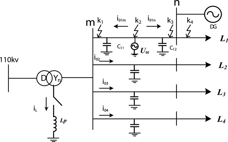
FIGURE 1. System zero-sequence equivalent network.
The small current grounding system shown in Figure 1 has four outlets. It is assumed that the line L1 has a single-phase grounding fault on the mn-segment line, k1 ∼ k4 is the location of the fault, Lp is the equivalent inductance of the arc suppression coil, iL is the inductive current flowing through the arc suppression coil, U0f is the zero-sequence voltage source, C11 and C12 are the capacitors at both ends of the mn-segment line on the line L1, and DG is a large-capacity distributed generation.
Distributed generation is connected to the power distribution network at n point. When a single-phase grounding fault occurs in the distribution network, the connection of DG enhances the zero-sequence current (I0f) that occurs during the fault (Coster et al., 2010). The mn section line is regarded as a double-ended power supply line. After the single-phase ground fault occurs, the current measured at the outlet of each line is:
When a single-phase ground fault occurs in line L1, one end of each line in the system near the fault point will flow through the capacitive current generated by itself. These currents enter the fault line through the grounding point, and the zero-sequence currents on both sides of mn are in the same phase when the fault occurs in the mn section of the line, and in the opposite phase when the fault occurs outside the area. The zero-sequence current amplitude on the m side is related to the power supply size of the system, and the zero-sequence current amplitude on the n side is related to the size of the DG (Hussain et al., 2010). When a single-phase grounding fault occurs in the L2 ∼ L4 section of the transmission line, it is an out-of-area fault relative to the mn section of the line. The phase of the zero-sequence current on both sides of the mn is opposite, the m side flows to the line, and the n side flows to the bus.
Feature Mode Decomposition (FMD) is designed as a non-recursive decomposition method (Miao et al., 2023). By initializing the FIR filter bank and updating the filter coefficients, different modes can be adaptively selected at the same time. The filtering process is inspired by the deconvolution theory, and the adaptive FIR filter is designed by iteratively updating the filter coefficient, so that the filtered signal infinitely approximates the deconvolution objective function. The filter is updated using CK as the objective function in FMD, and by comparing the correlation coefficient (CC) of each two modes, the smaller modes of CK are discarded from the two modes with the largest CC, and finally the decomposition is terminated when the termination condition is met. Using maximum CK deconvolution (IMCKD), the optimal FIR filter coefficient can be obtained without taking the failure period as a prior knowledge. IMCKD analog signals are used for processing to test the filtering performance of FIR filters with different initialization methods.
By labeling the original signal of length N as x(N), FMD theory becomes a solution to a constraint problem, expressed as:
where uk(n) is the kth decomposition mode. fk is the kth FIR filter with a length of L, where Ts is the input period measured using the number of samples. M is the order of the shift. For the constraint problem in Equation 2, eigenmode decomposition is an iterative eigenvalue decomposition algorithm, and the decomposition method can be represented in matrix form.
The CK of the decomposition mode can be defined as:
Superscript T is a conjugate transpose operation. WM is used as an intermediate variable to control the weighted correlation matrix.
Substituting Equation 4 into Equation 8 yields:
Among them, Rxwx and RXX are weighted correlation matrices and correlation matrices, respectively. Mathematically, (7) the maximization of the filter coefficients is equivalent to the eigenvectors associated with the maximum eigenvalue λ of the following generalized eigenvalue problem:
Therefore, during the iteration, the kth filter coefficient will be updated by the solution of (8) so that it constantly approximates the set target, which is CK’s maximum filtered signal.
The final mode will contain specific components from the original signal. FMD selects only the mode with the largest CK value. Therefore, if the FMD updates all initialized filters from start to finish, many patterns may contain the same components. To eliminate modal mixing or redundant modes, lock the mode with the largest CC first, because a higher CC means that both modes contain more of the same component. At the same time, in order to retain the mode with more fault information, among the two modes with the largest CC, the mode with smaller CK is abandoned, and the CC of the two modes of up and uq is defined as:
where and are the averages of the mode UP and UQ, respectively.
FMD uses filter update and period estimation, and adopts adaptive FIR filter to make component separation more thorough. Even in the face of complex faults, FMD can accurately decompose fault information. The theoretical waveform shown in Figure 2A is mainly composed of three frequency waveforms and white noise. When the modulus is set to 4, both VMD and FMD can extract the modes at each frequency. Figure 2B is the spectral information of the three effective components after the decomposition of the two methods.
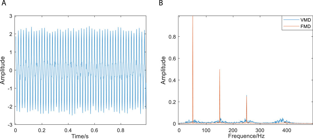
FIGURE 2. Experimental waveforms and comparison of two decomposition methods. (A) Experimental signals. (B) Comparison of the effects of the two decomposition methods.
In the spectrum of Figure (b), although the active ingredients can be extracted by the two decomposition methods, it is clear that the modal components of FMD are more concentrated and the filtering effect is better, compared with VMD, FMD filters are not limited by filter shape and bandwidth, have stronger adaptive ability, and can extract richer fault information. However, the proposed FMD still needs further improvement, and the input parameters such as modulus n and segment number K have a significant impact on the performance and efficiency of FMD.
From the above FMD decomposition steps, it can be seen that signal decomposition needs to determine the appropriate modulus n, the number k of modal functions, and the filter length L. n affects the distribution of active components of each mode after decomposition; k is used to determine the number of segments used to split the frequency band, which needs to meet k ≥ n, but a large value of k will cause computational redundancy; When the filter length L fluctuates within a suitable range, the choice of filter length has little effect on the filter performance. FMD itself is adaptive, can rely on the observation of the degree of separation of each mode to determine various parameters, but direct observation has a large error, so this paper uses the whale optimization algorithm (WOA) to sample entropy as the objective function to optimize the input parameters of FMD, its basic principle mainly includes three processes of rounding up prey, bubble net attack and searching for prey [26], briefly summarized as follows:
(a) Rounding up prey: determine the optimal hunting individual, and the rest of the hunting individuals update the position to the optimal individual, the formula is embodied as:
Where
(b) Bubble net attack: Humpback whales have specific aggressive behavior when surrounding their prey, which is completed by forming unique bubbles along the spiral path, and the position of the individual is updated to:
where is the distance between the current hunting individual and the optimal hunting individual, b is the spiral parameter of the path, and l takes a random value on [−1, 1].
(c) Search for prey: In the search stage, there is no optimal hunting individual in the whale, in order to ensure random distribution within the search range and ensure population diversity, appropriate adjustments need to be made:
where is the position of a random whale individual in the current population.
As shown in Figure 1, the zero-sequence current flow direction at both ends of the single-phase grounding fault in the mn section is different from that of the normal situation and the fault outside the mn section. Therefore, this paper intends to introduce a distance function, which can directly reflect the waveform difference between the two ends of the line, that is, the two sides of the mn.
Derivative dynamic time warping (DDTW) is a method used to compare and measure the similarity between two sequences. When calculating the distance between time series, DDTW introduces the derivative information of time series to better capture the trend and change of time series. It can adaptively deal with the different scales of time series and improve the accuracy of similarity measurement, which is more suitable for studying the problems in this paper.
Taking the above Figure 1 system as an example, it is assumed that the time series of the current on both sides are i1 (m side) and i2 (n side), respectively. First, the two sequences need to be standardized:
In the formula:
In the formula,
Here,
Combined with the preceding analysis, it becomes evident that under perfect conditions, for faults outside the line area, if the current amplitude ratio on both sides is 1 and the phase difference is 180°, the DDTWdist value is 90. On the other hand, for internal faults, if the current amplitude ratio of both sides is 1 and the phase difference is 0°, the DDTWdist value is 0. When the phase fluctuation of signals on both sides of internal and external faults ranges within 20° and the amplitude ratio is within 1.2, the value range of DDTWdist for external faults can be determined using formula (23) as (76.54, 90), whereas the value range for internal faults is (0, 36.35). It is essential to provide a certain margin for the scheme’s reliability. Therefore, the protection action boundary has been set to Dset = 40, and the protection braking value Dres = 60 to ensure timely and accurate triggering of the protection measures during actual operation and guarantee safe power system operation.
Based on all above analysis, this paper proposes a new scheme of distribution network differential protection based on WOA-FMD analysis. Specifically, when a ground fault occurs in the system, it will lead to an increase in zero-sequence voltage. Consequently, by comparing the measured zero-sequence voltage with the standard zero-sequence voltage, it becomes feasible to ascertain the presence of a ground fault.
Using two common grounding faults as illustrations, in the event of single-phase grounding, the neutral sequence voltage escalates to the amplitude of the phase voltage. In cases of two-phase short-circuit grounding, the neutral sequence voltage rises to 0.5 times the amplitude of the phase voltage. Ordinarily, the neutral sequence voltage should ideally be maintained at zero during normal system operation; however, fluctuations in neutral sequence voltage triggered by other factors remain a possibility (Tang et al., 2021). In accordance with the specifications outlined in DL/T 620-1997“Overvoltage Protection and Insulation Coordination of AC Electrical Equipment, " (Guo et al., 2022) the automatic tracking compensation arc suppression device must ensure that under normal operating conditions, the long-term voltage displacement of the neutral point does not surpass15% of the nominal phase voltage of the system. Therefore, when establishing the start-up value, it is imperative to account for these fluctuations, leading to the setting of the start-up value at 0.3 times the amplitude of the phase voltage, equivalent to Uon = 0.21Un.
FMD can extract the fault feature components in waveform well. Considering the large error of parameter setting by human, WOA is used for parameter optimization for the first time in this paper, and DDTW is further used to establish a specific protection scheme. Through verification, it has been observed that significant parameter changes in the system have an impact on the optimal parameters of FMD, subsequently affecting the decomposition effect. Consequently, it becomes necessary for the WOA to update the FMD parameters when there are changes in the equipment’s state within the system. This ensures the normal operation of the proposed scheme.
The specific steps of the protection scheme in this paper are as follows:
(1) According to the neutral voltage value to determine whether the system failure, if yes, start the whole algorithm;
(2) Once the algorithm is initiated, the optimized parameters obtained from the WOA are inputted into the FMD process. However, in cases where significant disturbances occur within the system, such as the switching of high-power equipment, it becomes necessary to restart the optimization algorithm. This ensures that the parameters L and k, crucial for accurate decomposition, are updated to reflect the current state of the system.
(3) The collected zero sequence current is decomposed by FMD to obtain each mode component.
(4) Calculate the DDTW value based on the maximum component of fault characteristics decomposed.
(5) According to the value of DDTW, determine whether this specific section of the power line under investigation is faulty, and act according to the judgment result.
The primary steps of the proposed protection scheme are depicted in Figure 3.
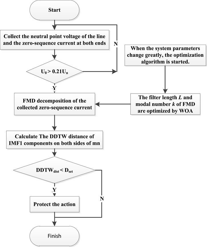
FIGURE 3. The flow chart of the new scheme.
The distribution network system with DG will change the distribution of fault current under fault condition, and due to the compensation effect of arc suppression coil, the characteristics of system fault current are not obvious after single-phase grounding short-circuit fault occurs. The action value and braking value of traditional differential protection are not much different, and it is easy to produce no action. Therefore, the criterion proposed in this paper is based on the use of transient zero-sequence current, the improved FMD decomposes the fault signal, and finally uses DDTW to simplify the judgment. Compared with the traditional protection, it has better reliability and higher sensitivity.
The experiment uses Simulink in Matlab to build a distributed power distribution network system model as shown in Figure 1, the line model adopts the Distributed Parameters Line model, a total of 4 outlets, line L1 is set as overhead line, line L2, L3 is the cable line, feeder L4 is the cable mixed line, the line length is different, where L1 = 30 km, L2 = 15 km, L3 = 20 km, L4 = 40 km. The line parameters are listed in Table 1. The transition resistance is set to 0, that is, the metal short circuit, the initial phase angle of the fault is 0°, the capacity of the distributed power supply is 1.5 MW, the arc suppression coil is set to 10% overcompensation, and the inductance value is 1.05 H.
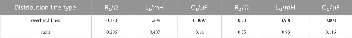
TABLE 1. Line parameters.
In order to fully study the influence of fault points in different locations on the criterion, this paper sets four single-phase ground faults at k1∼k4 on line L1 for verification (k1, k2 and k3 are faults in the area, and k4 is the fault outside the area); The impact of a two-ended power supply was prioritized and the simulation was validated with a single-ended power supply.
The zero-sequence current waveforms on both sides of the MN at different points of fault are shown in Figure 3:
As shown in Figure 4, the three figures (a)(b)(c) are the waveforms of the zero-sequence current on both sides of the mn when the fault occurs in the mn segment line, and the waveform phase is approximately the same, and (d) shows the waveform of the zero-sequence current on both sides of the mn when the fault occurs on the outside of the mn segment line, and the waveform phase is opposite.
FIGURE 4. Zero-sequence current waveforms on both sides of the sin-gle-phase ground fault MN at different locations: (A) A fault occurs at k1 (B) A fault occurs at k2 (C) A fault occurs at k3 (D) A fault occurs at k4.
Firstly, the WOA algorithm is used to optimize the parameters of the theoretical signal constructed in section 1. 2, so as to optimize the noise reduction effect. The optimization process of the filter length L and the number of modal decomposition is shown as follows:
It can be seen from Figure 5 that when the number of modal decomposition reaches 4, it tends to be stable. If the selected value is too high, it may cause over-decomposition. Therefore, the optimal decomposition number k = 4 is selected, and the corresponding filter length L = 50 is selected. The two optimal parameters are input to perform FMD decomposition on the experimental signal. The effect is as follows:
FIGURE 5. Filter length and modal decomposition number optimization curves.
The imaginary line in Figure 6 is the original harmonic signal of the experimental signal. The IMF1, IMF2 and IMF3 components are basically coincident with the experimental signal, and the decomposition effect is good. IMF4 contains the noise part.
FIGURE 6. WOA-FMD processing results of experimental signals.
The zero-sequence current on both sides of mn obtained by simulation is used as input for FMD decomposition. The waveform of the current components at both ends of mn after processing is shown in the figure:
Figure 7 is the IMF1 component of the zero-sequence current at both ends of the mn obtained by WOA-FMD decomposition. The original fault signal, VMD processing results on both sides of mn and FMD processing results are used to calculate the DDTW distance, and combined with other possible fault conditions, the value of DDTWdist when two-phase ground short circuit is considered. The results are shown in Table 2.
FIGURE 7. Zero-sequence current IMF1 component on both sides of mn.
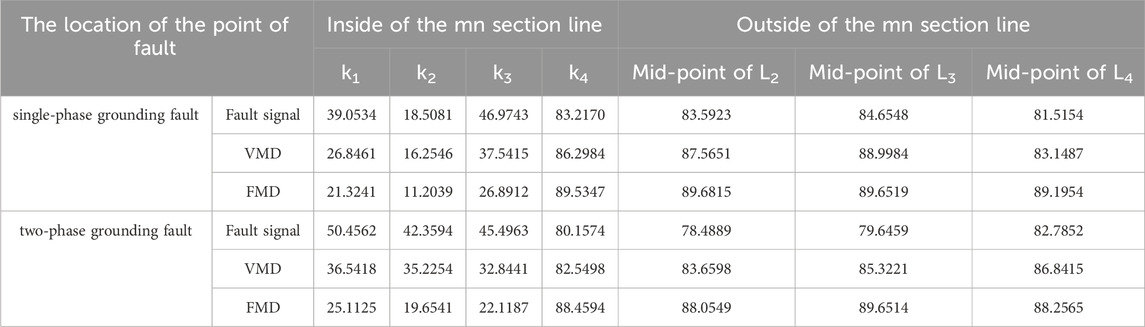
TABLE 2. The DDTW values of the m-side and n-side of the distribution system with DG.
Based on the DDTWdist calculation values depicted in Table 2, it is evident that FMD excels in extracting fault characteristics and proficiently discerning fault scenarios that elude detection in the original fault signal. The experimental findings highlight the superior performance of the improved FMD compared to VMD, operating effectively within the designated braking and action thresholds. Furthermore, the improved FMD can also precisely identify two-phase ground faults, where DDTWdist < Dset in instances of internal faults, and DDTWdist > Dres in cases of external faults, demonstrating notable efficiency and accuracy.
The proposed protection scheme is verified by selecting a location to simulate a single-phase non-metallic short-circuit fault in the internal and external faults respectively: the midpoint of the mn line is selected in the zone, and the outlet side of the n point is selected outside the zone. The DDTWdist calculated by different transition resistance Rg (0–100Ω) and different fault initial angles when a short-circuit fault occurs is shown in Table 3. For the convenience of observation, the change trend of DDTWdist with Rg is made into the curve shown in the following Figure 8.
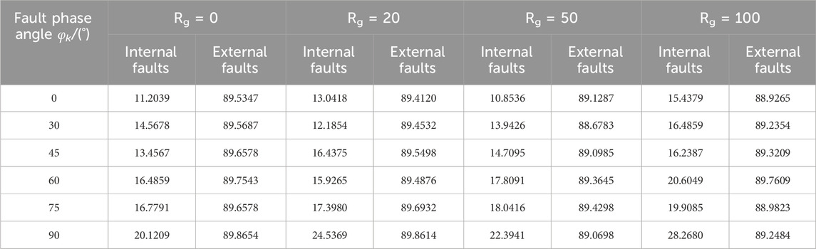
TABLE 3. Comparison of DDTW distances under different fault conditions.
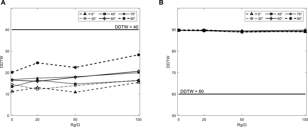
FIGURE 8. The trend of change in DDTWdist. (A) internal faults. (B) external faults.
Each curve of the internal fault in Figure 8A varies greatly. Although the overall trend is on the rise, it does not exceed the action value, that is, the protection scheme has a certain resistance to transition resistance. The variation of each curve of the external fault is not large, and it is almost not affected by the transition resistance. When there is a fault in Figure 8B, there are differences between different curves but they can all act correctly. There is almost no difference between different curves when the fault occurs outside the fault zone, that is, the protection scheme is not affected by the fault starting angle.
Based on the above analysis, the protection scheme has a certain ability to withstand transition resistance, and is less affected by the fault starting angle. At the same time, because the value of the DDTWdist of the external fault is almost unchanged, the action value and the braking value can be adjusted appropriately according to the demand to ensure that the protection device can operate reliably.
The above scheme is based on the single-phase ground short-circuit fault of the system during the normal operation of DG. Considering the situation when the distributed generation exits, the effectiveness of the scheme in the case of a single power supply system is guaranteed, and the proposed action value and braking value are verified by disconnecting the DG in the system. Taking the four positions of k1 ∼ k4 as the fault point, the WOA-FMD decomposition of the zero sequence current components on both sides of the mn can obtain the result of Figure 9:
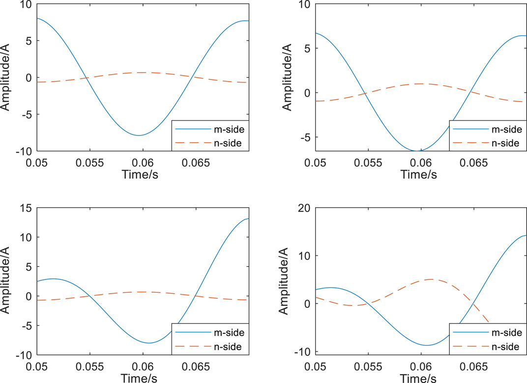
FIGURE 9. IMF1 components on both sides of mn when DG is out of operation.
It can be seen from Figure 9 that the amplitude of the fault current in the distribution network system when DG exits is very small, and it is difficult to judge the phase relationship. The proximity of the traditional differential protection’s braking and action values poses a risk of failure. This scheme proposed in this paper introduces a scheme that enhances the conventional standard by addressing its limitations. Through the calculation of DDTWdist for the IMF1 component derived from the WOA-FMD decomposition, Table 4 data can be obtained:
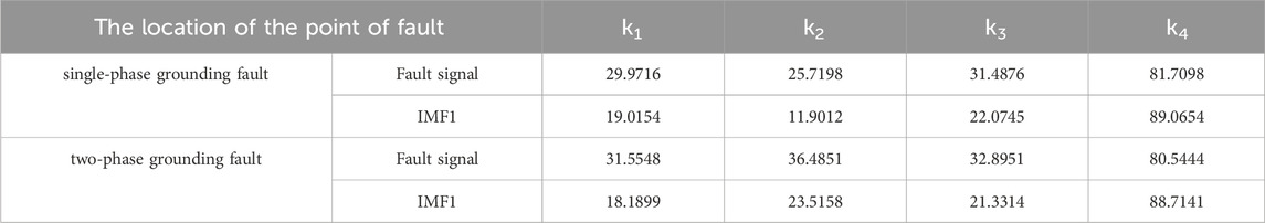
TABLE 4. The DDTW values of m-side and n-side when DG is out of operation.
The data presented in Table 4 indicates that the DDTW distance calculation results of IMF1 components for two distinct fault types at both ends of mn are lower than the untreated values in the case of an internal fault, whereas they exceed the untreated values for an external fault. The substantial difference between these values is evident, and the action conditions are met during an internal fault scenario. The significant deviation from the action value Dset enhances the effectiveness of protection actions. In a unilateral power supply system, the small amplitude of zero-sequence current on the non-powered side (n-side) may impact the protection mechanism. Consequently, verification is conducted using 24-point data samples from a single power supply at different time instances, ensuring a maximum error within ±2. This verification proves that the protection scheme is still unaffected, that is, this scheme is effective when DG exits operation.
In this paper, a differential protection algorithm based on WOA-FMD processing system zero-sequence current is proposed, which further amplifies the fault characteristics at both ends of the line through the proposed derivative dynamic time warping, and uses the obtained DDTW value to discriminate.
The scheme has a wide application range. In the distribution network with DG, the mn section line with this protection can be approximately equivalent to a two-terminal power supply network. Through simulation verification, this algorithm is also applicable to the distribution lines of ring network and double petal network, and the results are similar to those of DG system. In addition, the FMD and DDTW algorithms used in this paper reduce the dependence on synchronous sampling, have high reliability and strong anti-interference ability, and have significant advantages for the comparison of fault signals with large differences at both ends of the line. It can effectively improve the power supply reliability of the distribution network and solve the problem of protection misoperation caused by differential protection applied to the distribution network due to amplitude and other reasons. It has certain application prospects. However, the action value and braking value of the protection are obtained according to the simulation model. In order to ensure the accuracy of fault location, the specific setting value needs to be adjusted and optimized according to the actual distribution network parameters.
The original contributions presented in the study are included in the article/supplementary materials, further inquiries can be directed to the corresponding author.
LW: Writing–review and editing. XS: Writing–original draft. WJ: Writing–review and editing.
The author(s) declare that financial support was received for the research, authorship, and/or publication of this article. National Natural Science Foundation of China (61873159); State Grid Zhejiang Electric Power Co., Ltd. Science and Technology Project (5211TZ220002). The funder was not involved in the study design, collection, analysis, interpretation of data, the writing of this article, or the decision to submit it for publication.
Author WJ was employed by Jiaxing Power Supply Company of State Grid Zhejiang Electric Power.
The remaining authors declare that the research was conducted in the absence of any commercial or financial relationships that could be construed as a potential conflict of interest.
All claims expressed in this article are solely those of the authors and do not necessarily represent those of their affiliated organizations, or those of the publisher, the editors and the reviewers. Any product that may be evaluated in this article, or claim that may be made by its manufacturer, is not guaranteed or endorsed by the publisher.
Chao, C. X., Zheng, X. D., Gao, P., Tang, L., and Tu, Q. (2021). High frequency impedance differential protection with high proportion of photovoltaic power distribution network. Proc. CSEE 41 (12), 6968–6979. doi:10.13334/j.0258-8013.pcsee.201516
Chen, G., Liu, Y., and Yang, Q. (2020). Impedance differential protection for active distribution network. IEEE Trans. Power Del. 35 (1), 25–36. doi:10.1109/tpwrd.2019.2919142
Coster, E. J., Myrzik, J. M. A., Kruimer, B., and Kling, W. L. (2010). Integration issues of distributed generation in distribution grids. Proc. IEEE 99 (1), 28–39. doi:10.1109/jproc.2010.2052776
Gao, H., Li, J., and Xu, B. (2017). Principle and implementation of current differential protection in distribution networks with high penetration of DGs. IEEE Trans. Power Deliv. 32 (1), 565–574. doi:10.1109/tpwrd.2016.2628777
Gao, Y., Li, Y., Chen, X., Zhao, Z., Wang, Q., and Ren, J. (2021). Adaptive differential protection principle based on current amplitude ratio. Proc. CSU-EPSA 33 (2), 1–7. doi:10.19635/j.cnki.csu-epsa.00054
Guo, M.-F., Cai, W.-Q., Zheng, Z.-Y., and Wang, H. (2022). Fault phase selection method based on single-phase flexible arc suppression device for asymmetric distribution networks. IEEE Trans. Power Deliv. 37 (6), 4548–4558. doi:10.1109/tpwrd.2022.3150914
Hussain, B., Sharkh, S. M., Hussain, S., and Abusara, M. A. (2010). “Integration of distributed generation into the grid: protection challenges and solutions,” in Proc. 10th IET Int. Conf. Develop. Power Syst. Protect. Manag. Change, Manchester, UK, March, 2010, 1–5.
Li, X., and Lu, Y. (2020). ‘Improved amplitude differential protection scheme based on the frequency spectrum index for distribution networks with DFIGbased wind DGs. ’’ IEEE Access 8, 64225–64237. doi:10.1109/access.2020.2984031
Liang, R., Wang, F., Fu, G., Xue, X., and Zhou, R. (2016). A general fault location method in complex power grid based on wide-area traveling wave data acquisition. Int. J. Elect. Power Energy Syst. 83, 213–218. doi:10.1016/j.ijepes.2016.04.021
Lin, X., Zhao, F., Wu, G., Li, Z., and Weng, H. (2012). Universal wavefront positioning correction method on traveling-wave-based fault-location algorithms. IEEE Trans. Power Del. 27 (3), 1601–1610. doi:10.1109/tpwrd.2012.2190108
Lin, Z., Ruan, X., Wu, L., Zhang, H., and Li, W. (2020). Multi resonant component-based grid-voltage-weighted feedforward scheme for grid-connected inverter to suppress the injected grid current harmonics under weak grid. IEEE Trans. Power Electron. 35 (9), 9784–9793. doi:10.1109/tpel.2020.2970514
Linli, Z., Houlei, G., Bingyin, X., and ongduan, X. Y. (2012). “Fault location method based on zero sequence admittance measurement in non-effectively earthed system,” in Proc. IEEE PES Innov. Smart Grid Technol., Tianjin, China, May, 2012, 1–4.
Miao, Y., Zhang, B., Li, C., Lin, J., and Zhang, D. (2023). Feature mode decomposition: new decomposition theory for rotating machinery fault diagnosis. IEEE Trans. Industrial Electron. 70 (2), 1949–1960. doi:10.1109/tie.2022.3156156
Ray, P., and Mishra, D. P. (2016). Support vector machine based fault classification and location of a long transmission line. Eng. Sci. Technol. Int. J. 19 (3), 1368–1380. doi:10.1016/j.jestch.2016.04.001
Tang, J., Xiong, B., Li, Y., Yuan, C., and Qiu, Y. (2021). Faulted feeder identification based on active adjustment of arc suppression coil and similarity measure of zero-sequence currents. IEEE Trans. Power Deliv. 36 (6), 3903–3913. doi:10.1109/tpwrd.2021.3051040
Ustun, T. S., and Khan, R. H. (2015). Multiterminal hybrid protection of microgrids over wireless communications network. IEEE Trans. Smart Grid 6 (5), 2493–2500. doi:10.1109/tsg.2015.2406886
Wang, P., Zhou, H., Chen, B., Tian, C., Chen, B., and Sun, B. (2019). Fault location method in resonant grounded networks based on distributed modulation and compensation adjustment. IEEE Trans. Power Del. 34 (5), 1938–1947. doi:10.1109/tpwrd.2018.2883352
Wang, X., Gao, J., Chen, M., Wei, X., Wei, Y., and Zeng, Z. (2018). Faulty line detection method based on optimized bistable system for distribution network. IEEE Trans. Industrial Inf. 14 (4), 1370–1381. doi:10.1109/tii.2017.2753227
Zhang, X., Ma, X., Zhang, L., Wang, Z., Lin, X., Li, Z., et al. (2020). Novel current amplitude differential protection criterion for line with unmeasurable branch in active distribution network. Electr. Power Autom. Equip. 40 (2), 76–84. doi:10.16081/j.epae.202001006
Zhang, Z., Liu, X., and Piao, Z. (2014). Fault line detection in neutral point ineffectively grounding power system based on phase-locked loop. IET Gener. Transm. Distrib. 8 (2), Feb. doi:10.1049/iet-gtd.2013.0235
Zhao, S., Tang, T., Wang, D., Gao, R., and Wu, Z. (2017). “Active distribution network protection scheme based on area current direction,” in Proc. China Int. Electr. Energy Conf. (CIEEC), Beijing, China, October, 2017, 247–251.
Keywords: distribution network, whale optimization algorithm(WOA), feature mode decomposition(FMD), derivative dynamic time warping(DDTW), differential protection
Citation: Wang L, Song X and Jiang W (2024) Differential protection scheme for distribution network with distributed generation based on improved feature mode decomposition and derivative dynamic time warping. Front. Energy Res. 12:1369880. doi: 10.3389/fenrg.2024.1369880
Received: 13 January 2024; Accepted: 05 March 2024;
Published: 15 March 2024.
Edited by:
Weihang Yan, National Renewable Energy Laboratory (DOE), United StatesReviewed by:
Kenneth E. Okedu, Melbourne Institute of Technology, AustraliaCopyright © 2024 Wang, Song and Jiang. This is an open-access article distributed under the terms of the Creative Commons Attribution License (CC BY). The use, distribution or reproduction in other forums is permitted, provided the original author(s) and the copyright owner(s) are credited and that the original publication in this journal is cited, in accordance with accepted academic practice. No use, distribution or reproduction is permitted which does not comply with these terms.
*Correspondence: Xin Song, Z29oZGRpbkAxNjMuY29t
Disclaimer: All claims expressed in this article are solely those of the authors and do not necessarily represent those of their affiliated organizations, or those of the publisher, the editors and the reviewers. Any product that may be evaluated in this article or claim that may be made by its manufacturer is not guaranteed or endorsed by the publisher.
Research integrity at Frontiers
Learn more about the work of our research integrity team to safeguard the quality of each article we publish.