
94% of researchers rate our articles as excellent or good
Learn more about the work of our research integrity team to safeguard the quality of each article we publish.
Find out more
ORIGINAL RESEARCH article
Front. Energy Res., 16 February 2024
Sec. Nuclear Energy
Volume 12 - 2024 | https://doi.org/10.3389/fenrg.2024.1368303
This article is part of the Research TopicThermal-Hydraulics in Once-Through Steam Generator (OTSG) for Nuclear ReactorsView all 5 articles
 Xianghui Lu
 Xin Wang*
 Xiong Zheng
 Xiting Chen
 Shuqi MengTianming RuanJun ChenYulong MaoYisong HuChaohao Shang
Introduction: A simulation model was developed by coupling a one-dimensional (1D) system code and 3D CFD software, to analyze the three-dimensional (3D) flow and heat transfer characteristics of the once-through steam generator (OTSG).
Methods: The shell side of the OTSG was simulated by FLUENT, and the tube side was simulated by the system code LOCUST. Through spatial mapping, the 1D and 3D simulations were coupled along the outer wall of the OTSG's helically coiled tubes.
Results and Discussion: This coupling method enabled the acquisition of high-resolution flow and heat transfer characteristics of the OTSG, and the error of heat flux calculation result by the coupled model is within 15%. Through coupling simulation analysis of the prototype OTSG, it was found that the inlet and outlet temperature difference reached as high as 150°C. The unevenness of the radial temperature distribution increased along the flow direction, and the wake swing effect caused by the sweeping flow of the tube bundle at the exit position was evident. The results of this study provide reference and a coupled simulation method for the engineering design and thermal-hydraulic characteristics analysis of OTSG.
The Once-Through Steam Generator (OTSG) boasts superior heat transfer efficiency, and the capability to produce steam at higher pressures and temperatures compared to traditional pressurized water reactor steam generators. Additionally, OTSG enables more flexible operational strategies to accommodate variations in the reactor loop power and the grid load. Its compact structure makes it suitable for modular reactor designs. During operation, the OTSG helically coiled tubes experience complex two-phase flow heat transfer phenomena, with centrifugal forces impacting pressure and temperature within the tubes. Issues such as flow instability may occur, leading to degradation in heat transfer performance, power reduction, or tube rupture, adversely affecting reactor operation. Therefore, the prediction and analysis of the flow and heat transfer characteristics of OTSG are crucial.
Presently, OTSG finds extensive applications in small and medium-sized advanced reactors, including sodium-cooled fast reactors, small water reactors, high-temperature gas-cooled reactors, and lead-cooled fast reactors. As the development of small modular reactors progresses rapidly, numerous studies have focused on simulating and predicting the flow and heat transfer characteristics of OTSG.
Xu et al. (2021) evaluated the applicability of heat transfer and friction coefficient models for helically coiled tubes and successfully applied well-suited models to the RELAP5 code, simulating the steady-state flow and heat transfer behavior of helically coiled tubes. Their results aligned well with experimental data and captured flow instability phenomena using a modified model. Huang et al. (2020) developed the NUSOL-SG program, incorporating a two-fluid two-phase flow model considering thermal non-equilibrium for thermal-hydraulic analysis of the helically coiled tubes steam generator. The program embedded heat transfer and pressure-drop relationships, and the results demonstrated good agreement with RELAP5 calculation. Chen et al. (2019) developed the THOSG code for thermal-hydraulic analysis, simulating the thermal-hydraulic behavior of OTSG by coupling flow and heat transfer on the primary and tube sides. Yao et al. (2021) developed the code TACS, utilizing a homogeneous flow model for simulating two-phase flow in helically coiled tubes. TACS performed thermal-hydraulic characteristic analysis on OTSGs with varying thermal and geometric parameters. Niu et al. (2016) conducted numerical simulations of uniform single-side heating in pipes using the commercial CFD software FLUENT, based on the VOF and the Realizable k-ε turbulence model. The study explored the thermohydraulic characteristics of flow in helically coiled tubes under different heating conditions. Sun et al. (2018) numerically simulated nucleate boiling heat transfer in helically coiled tubes using the Eulerian two-fluid model with commercial CFD software FLUENT. Jo et al. (2009), Prattipati et al. (2021), and Sun et al. (2018) used the Eulerian two-fluid model for boiling heat transfer calculations in helically coiled tubes. However, due to the complex two-phase flow patterns in helically coiled tubes transitioning from bubbly to churn, slug, annular, and dispersed flows, with different models for interface concentration and interphase mass, momentum, and energy transfer, there is no universal sub-model between phases. Heydari et al. (2021) employed the Taguchi optimization method to analyze the heat transfer performance of helically coiled corrugated tube heat exchangers of different geometric parameters and operational conditions. Etghani and Baboli (2017) also used the Taguchi method to conduct heat transfer and friction loss analyses on helically coiled tube heat exchangers, focusing on the influence of pitch, tube diameter, and shell-side flow rate. Xu et al. (2022) investigated the effects of groove shapes and depths on the heat transfer of helically coiled tube heat exchangers using software such as SolidWorks and ANSYS FLUENT. Mirgolbabaei (2018) evaluated the heat transfer performance of helically coiled tube heat exchangers under different mass flow rates, coil diameters, and pitches using CFD simulations. Kim et al. (2016) studied heat exchangers with bumps and depressions on helically coiled tubes, analyzing heat transfer performance under different flow rates and inlet temperatures. Mansour et al. (2019) simulated upward air-water two-phase flow in vertical helically coiled tubes under adiabatic conditions using the commercial CFD software Star-CCM + based on the VOF model. The study revealed that the realizable k-ε model predicted velocity distribution on the vertical centerline more accurately, while the SST k-ω model predicted velocity distribution on the horizontal centerline more accurately.
In contrast to the analysis methods mentioned above, this paper proposes a one-dimensional (1D) and three-dimensional (3D) coupling simulation method for the flow and heat transfer characteristics of OTSG. For 1D two-phase flow heat transfer inside the tubes (the tube side of OTSG), considering the complexity of two-phase flow heat transfer, a system analysis program is used to establish a parallel multi-channel model. For 3D single-phase flow heat transfer outside the tubes (the shell side of OTSG), FLUENT is employed to establish a 3D analysis model. By mapping the spatial domain, a coupled heat transfer model is established for both inside and outside the tubes, providing a 3D distribution of flow and heat transfer characteristics for OTSG. This approach supports the fine design and analysis of OTSG.
An Once-Through Steam Generators (OTSGs) consist of the helically coiled tubes and the outer shell. Tube sideshell sideSteam is generated by heating the water inside the helically coiled tube (tube side) by the high-temperature fluid of the shell side. In the tube side, a complex convective heat transfer phenomenon involving the transition from single-phase to two-phase fluid, while the external flow consists of a single-phase fluid with non-uniform axial and radial temperature distributions. To simulate the flow and heat transfer of OTSG more accurately, this study employs a coupled calculation method using 1D system programs and 3D Computational Fluid Dynamics (CFD) programs for a comprehensive high-resolution analysis of the overall flow and heat transfer characteristics of OTSG. For the complex phase-change heat transfer within the helical tubes, a heat transfer model with higher applicability and accuracy is used, simulated through 1D system programs. For the external single-phase fluid, CFD calculations are utilized to capture the 3D effects of axial and radial flow heat transfer in the shell side flow passage more accurately during the heat exchange process of OTSG. Therefore, different heat transfer models are applied in the simulation for the internal and external sections of OTSG.
The flow and heat transfer in the OTSG shell side, where a single-phase fluid is present, are simulated using commercial CFD software. The fundamental governing equations Eqs. 1–3 for the simulation of flow and heat transfer include the continuity, momentum, and energy equations, respectively (De Schepper et al., 2008; Yang et al., 2008; Xie et al., 2015; Jiaqiang et al., 2016):
Among the turbulence calculation models, the Reynolds time-averaged model RANS (Reynolds Average Navier-Stokes) is more widespread, reliable, and practical in numerical simulation studies and engineering design due to its high computational efficiency and accuracy. Therefore, in this study, the SST k-ω turbulence model with the RANS method is adopted in the CFD calculations with the following turbulence transport equations Eq. 4:
where ρ is the density; k is the turbulent kinetic energy; ω is the dissipation rate; u is the velocity; μ is the molecular viscosity coefficient; μt is the turbulent molecular viscosity coefficient; σk and σω are the diffusion coefficients of the turbulent kinetic energy for k and ω, respectively; Gk and Gω are the turbulent kinetic energy generated by the mean velocity gradient and the generation of ω; Yk and Yω are the dissipation of k and ω under turbulence; and Dω is the source term of definition.
In this study, the SST k-ω model in FLUENT using the enhanced wall function is used to reduce the mesh requirements for solving the turbulent model in the near-wall region so that it can be applied to different y + meshes, and can achieve simulation of the flow heat transfer characteristics of the shell side.
For the complex boiling two-phase flow heat transfer phenomena in tube side of OTSG, a 1D system code with two fluid model named LOCUST is used for analysis. The flow and heat transfer models modified for helically coiled tubes are used in LOCUST to ensure the accuracy of the simulation.
1) Flow model of tube side
The Eq. 5 for the friction pressure drop under single-phase conditions is as follows:
where λ is the frictional resistance coefficient; v is the velocity; D is the diameter of the tube; l is the length of the tube. The frictional resistance coefficient Eq. 6 is corrected by experimental data, which considered the Re, coil diameter
The two-phase wall drag coefficient Eq. 7 are selected from the most validated literature correlations taking into account the effects of secondary flow inside the tube side of OTSG (Colombo et al., 2015):
where
2) Heat transfer model
In the 1D system code, the heat transfer model of helically coiled tubes are modeled as inclined straight tubes. which are as follows.
1) Single-phase heat transfer section is calculated by the Dittus-Boelter equation, and a correction coefficient
where b and p are the correction parameters obtained from experimental data.
2) Nucleate boiling and transition boiling are calculated by the modified Chen equation (Seban and McLaughlin, 1963; Chen, 1966; Bjornard and Griffith, 1977) in Eq. 9:
where F and S represent the Reynolds number factor and suppression factor, respectively, Eqs. 10–12
where h is the heat transfer coefficient, k is the thermal conductivity; Xtt is the Matineli parameter.
3) The film boiling section is calculated by the Bromley equation (Radovcich, 1962; Hewitt, 1977; Choe et al., 1978) in Eq. 13:
where γ′ is the latent heat of vaporization; Δt is the temperature difference between the heated wall and the boiling temperature of the fluid.
In this study, the OTSG flow and heat transfer characteristics are calculated using a coupled simulation method. The shell side of the OTSG (outside of the helically coiled tubes) is simulated by LOCUST, a 1D system code developed by China General Nuclear Power Group (CGN). The tube side (inside the helically coiled tubes) is simulated by CFD software FLUENT. Use CORBA add-ons for FLUENT to establish an coupling face between FLUENT and system code, so that it is possible to manage the FLUENT session through Text User Interface (TUI) specific commands. Scripts were developed with Python to process the results of the calculations of the two programs and to transfer data between the coupling interface. The whole framework of the coupling procedure and the calculation flow are shown in Figure 1.
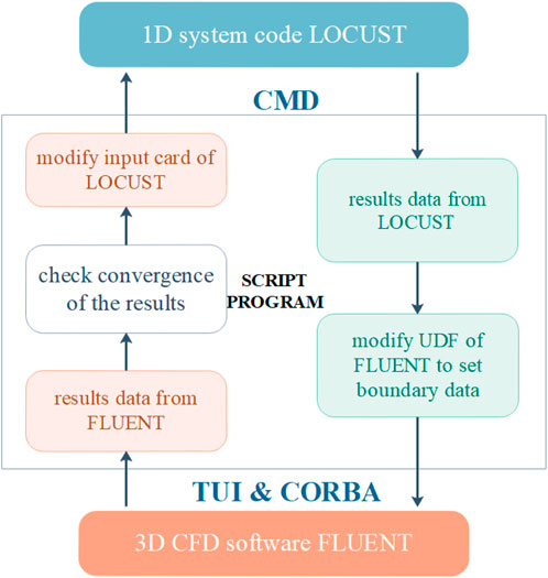
FIGURE 1. Schematic diagram of coupling calculation process controlled by batch program.
The script program drives the system code through CMD commands, reads the data on the coupling boundary at the end of the computation, and records the results in the UDF (User Defined Function), thus redefining the boundary conditions used in the FLUENT computation. After that, use the script to establish a connection with FLUENT by CORBA, and at the same time enable FLUENT’s aaS (as a Server) mode, so that it can drive FLUENT’s calculations by sending TUI (Text User Interface) commands to FLUENT. Finally, the convergence of the results of the coupled computation is checked to determine whether to continue the coupling iteration. If the results do not converge, the script program writes the results of the above calculations to the input card of the system code calculations and drives the system code calculations again, thus starting a new round of coupling iterations.
For the CFD computational domain of the shell side of the OTSG, an approximate division of the area is performed in the same way as the node division of the tube side by the system code. As shown in Figure 2, in the radial direction, the CFD computational domain is divided into five blocks, with a layer of helically coiled tube bundles wrapped in each region, corresponding to the five pipe components of the system code; in the axial direction, the tube side computational domain is divided into 80 blocks, with the height of each block being the same as the height of the corresponding node of the tube side by system code.
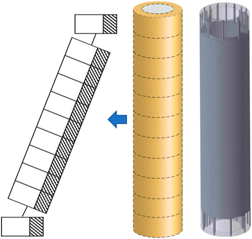
FIGURE 2. Schematic Diagram of Fluid Division on the Shell side.
In addition, the UDF macros used in the FLUENT coupling calculations are shown in Table 1, and these macros are used to define the boundary conditions on the coupling boundary, modify the fluid physical properties, and approximate the region of the shell side computational domain in the same way as the node partitioning of the tube side by system code.
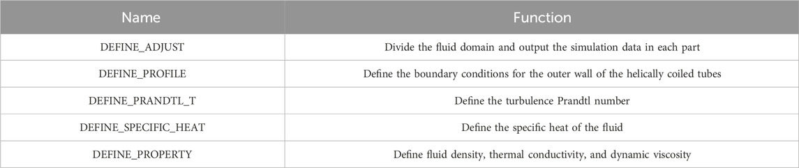
TABLE 1. Macros and functions of UDF.
The delivery of data in the coupling iteration process between CFD and 1D-system code is shown in Figure 3, in which the system code uses the first kind thermal boundary condition for calculation, and FLUENT uses the second kind. The specific solution processes are as follows:
1) Given a set of temperature distributions on the outer wall of the helically coiled tubes, and initialize calculations with the system code to calculate the flow heat transfer process inside the tubes;
2) After the system code analysis procedure is completed, the heat flux distribution on the outer wall of the tubes is transferred to FLUENT;
3) FLUENT uses this heat flux as the boundary condition to start calculating the convection process of the shell side of OTSG;
4) In FLUENT’s calculation process, after the temperature distribution in the fluid domain is relatively stable, it starts to read and record the temperature result data of the outer wall of the tubes in a certain time step;
5) After the FLUENT calculation, the recorded temperature data are arithmetically averaged to obtain the mean value of the temperature distribution;
6) Determine the convergence of the temperature distribution. If it converges, stop the coupling iteration; if there is no convergence, relax the temperature distribution and the temperature distribution result input to the system code in this iteration and use it as the system input data in the next calculation, and start the next coupling iteration;
7) Repeat the process from step 2) to step 6) until convergence is reached.

FIGURE 3. Data Transmission Flowchart using First and Second Type Boundary Conditions.
It should be added that during the coupled model development and calculations it was found that before the coupling process starts, an initial set of temperature distributions will be reasonably given based on the OTSG design conditions. And, when the initial temperature distribution is lower than the actual temperature distribution, it is helpful to ensure the stability of FLUENT in the subsequent calculation process; on the contrary, if the initial temperature distribution is higher than the actual temperature distribution, it will cause a high wall heat flux data delivery to FLUENT by the system code. This may cause unreasonable temperature values to appear in the shell side calculation domain during FLUENT’s calculations, causing the calculation to terminate. In addition, after the FLUENT calculation process is completed, if the wall temperature is not relaxed and directly transferred to the system code for calculation, the heat transfer power on the tube side will oscillate back and forth around the final value, causing the iteration to fail to converge; while using a small relaxation factor can ensure the stability of convergence during the iteration process, it will reduce the iteration convergence speed and cause a waste of computing resources. Therefore, it is necessary to select a relaxation factor that can not only ensure iterative convergence but also ensure a certain convergence rate during the coupling calculation process. In addition, the type of thermodynamic boundary conditions at the coupled boundary also affects the convergence efficiency of the calculation process. It is found in the calculations that the convergence efficiency of the boundary conditions on the outer wall surface of the helically coiled tube on the primary and tube sides of the OTSG is higher when the thermodynamic boundary conditions are taken as the second kind and the third kind respectively than other boundary conditions.
In this article, the coupling program calculation results are compared with the experimental results to preliminarily verify the correctness of the coupling program calculation results.
The experimental object is a small helically coiled tube OTSG, as shown in Figure 4. The experiment is carried out to study the overall heat transfer characteristics of the OTSG by measuring the inlet/outlet fluid temperatures and pressure drops, under different inlet temperatures and flow rates of the fluid of the primary and tube sides. The range of test conditions are shown in Table 2.
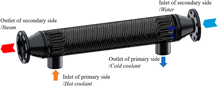
FIGURE 4. Schematic diagram of a small OTSG heat exchanger.
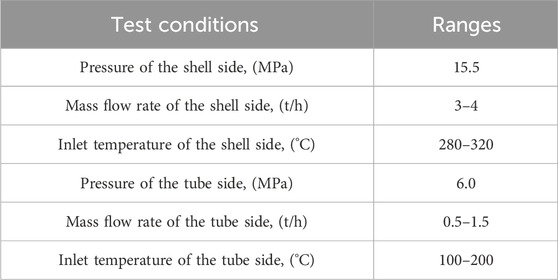
TABLE 2. Test conditions for OTSG.
The fluid in the primary and tube side of the OTSG are both water, and the outlet of the tube side is saturated steam. The diameter of the OTSG heat exchanger is about 30 cm, and the inlet and outlet pipe flange inner diameter of the OTSG is about 9 cm. There are five layers of the helically coiled tubes in the OTSG. The average length of the tube is 65 m, the diameter range of the helix is 120–200 mm, and the helix rising angle is 8.2°. In the experiments, the primary and tube side fluids are both water and the tube side outlet is saturated steam.
In the establishment of the CFD model of the OTSG, the experimental device was reasonably simplified to increase the computational efficiency, and the elliptical head at the inlet and outlet of the tube side of the OTSG was replaced by a cylindrical cylinder. In terms of meshing, a polyhedral mesh is used to fill the fluid domain, and a prismatic layer mesh is used in the near-wall position. The total number of meshes in the final computational model is 14 million after verification of mesh-independence. The simplified geometrical and mesh model of the OTSG are shown in Figure 5.

FIGURE 5. Geometric and mesh modeling of water-water steam generator.
Figure 6 shows the system code nodalization of the tube side of the OTSG. Since the system code cannot directly simulate the helical tubes, the helical heat exchanger tubes were equivalent to inclined straight tubes in this study (Cioncolini et al., 2003). Each layer of the helically coiled tubes is equivalent to 1 inclined straight pipe for calculation, and the angle of inclination is the helix rising angle. To give more accurate boundary conditions for the coupling interface in the coupling calculation with CFD, the node division of the axial direction of the model is encrypted. Each tube contains 80 nodes, of which the inlet straight section and outlet straight section both contain 5 nodes, and the helically coiled tube section contains 70 nodes.
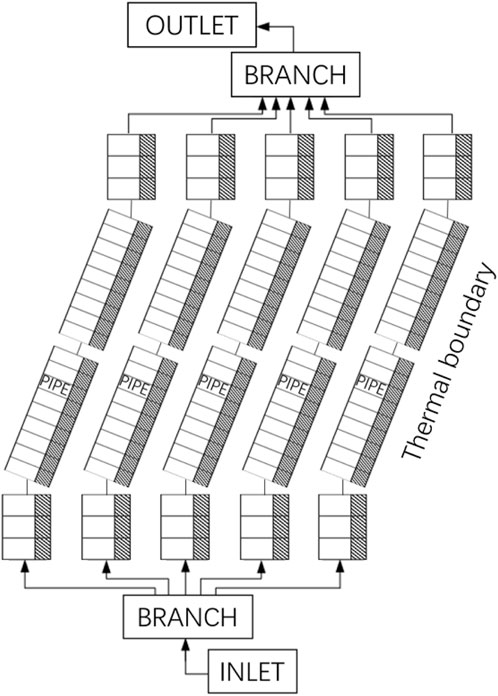
FIGURE 6. Tube side node diagram of water reactor heat exchanger.
The OTSG 1D and 3D coupled heat transfer calculation model developed in this study is preliminarily validated using experimental data. In the test, four test conditions were selected, respectively, with different primary and tube side inlet and outlet water pressures, flow rates, and temperatures, and the OTSG heat transfer power obtained from the test was compared with the results obtained from the calculation. As shown in Figure 7, it can be seen that the coupled calculated values are small relative to the experimental values, but the overall error is not large, all within 15%. Test conditions of each case of OTSG tests are shown in Table 3. And the uncertainty of the heating power in the test is 1.4%.
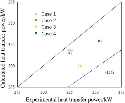
FIGURE 7. Comparison of coupling calculation results and experimental values.
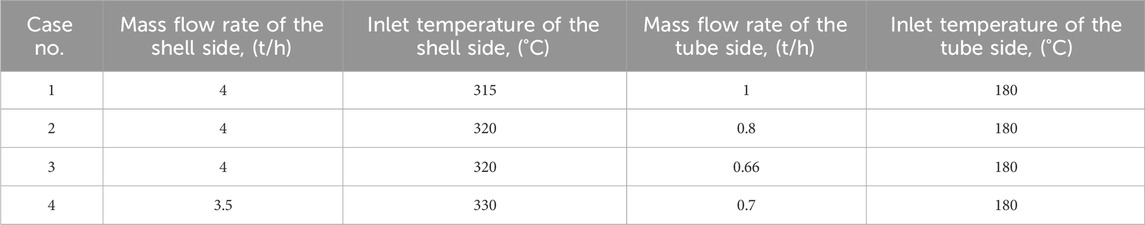
TABLE 3. Parameters of specific cases.
Figures 8, 9 show the wall temperature input data and heat flux output data of system code for the first-fifth and fifth-10th coupling iteration steps, respectively, of one coupling case. It can be seen that after five coupling iterations, the input values of wall temperature have basically converged, and the corresponding wall heat flux is also basically stable. Therefore, it can be preliminarily judged that, in the case of choosing a reasonable initial tube wall temperature, after a certain number of coupling calculations, relatively reliable OTSG heat transfer characteristics can be obtained, and the deviation of the calculated OTSG power from the experimental value is less than 15%.
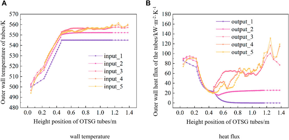
FIGURE 8. Wall temperature input and heat flux output of LOCUST during iteration step 1-5. (A) wall temperature. (B) heat flux.
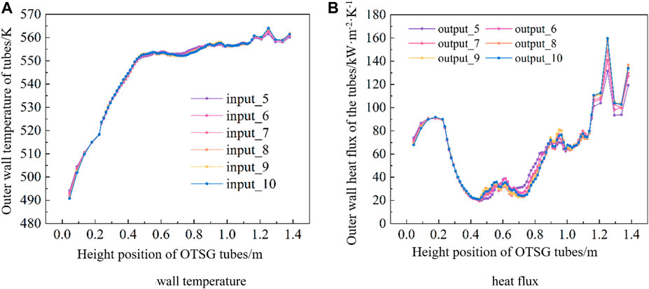
FIGURE 9. Wall temperature input and heat flux output of LOCUST during iteration step 5–10. (A) wall temperature. (B) heat flux.
A prototype designed OTSG with liquid lead-bismuth eutectic alloy on the shell side and water on the tube side is simulated using the 1D and 3D coupling method developed above. The inner and outer diameters of the annular flow channel of the OTSG are 376 and 596 mm, respectively, and it includes a total of 37 helically coiled heat transfer tubes in five layers, with a tube outer diameter of 16 mm and a tube wall thickness of 2 mm. The helix diameters, the number of tubes, and the helix rising angle are shown in Table 4. The shell side of the OTSG is simulated using FLUENT and the tube side is simulated using the system code, and the boundary conditions of the primary and tube sides are shown in Table 5. The coupling procedure is used to calculate the steady state of the OTSG, and the results of the overall temperature and flow fields of the primary and tube sides are obtained.

TABLE 4. Geometric parameters of the prototype OTSG helically coiled tubes.
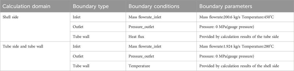
TABLE 5. Boundary conditions of the primary and tube sides.
The distribution of temperature and velocity on the vertical section of the shell side of OTSG is shown in Figure 10. The shell side fluid temperature gradually decreases along the process (from top to bottom, and the bottom Z = 0), and the radial distribution is relatively uniform, but the non-uniformity of the radial distribution increases. Regarding the velocity distribution, due to the influence of the swept flow of the tube bundle, local maximum and minimum points of velocity appear on the side of the tube, but the velocity distribution of the four internal tube bundle gaps is relatively uniform. It can be seen from the velocity vector diagram in Figure 11 that the wake swing effect caused by the tube bundle cross-flow is obvious. Especially at the outlet position of the tube bundle area, the velocity vector shows obvious asymmetry.
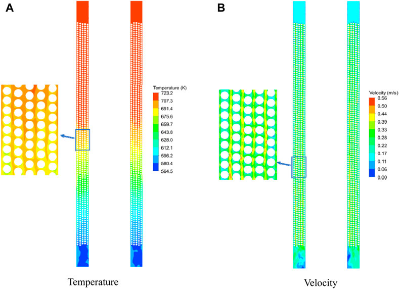
FIGURE 10. Distribution of temperature and velocity on the vertical section of the shell side of OTSG. (A) Temperature. (B) Velocity.
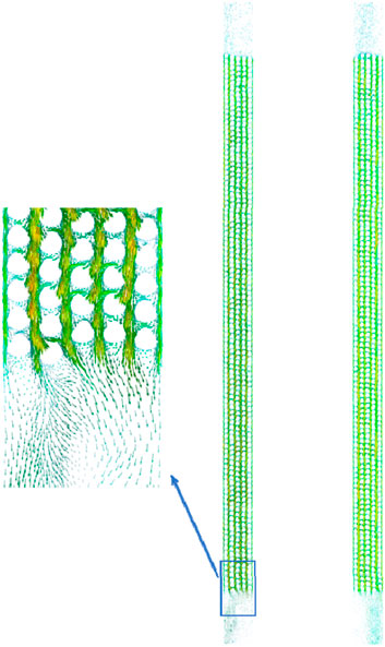
FIGURE 11. Velocity vector on the vertical section of the shell side of OTSG.
The temperature distribution diagrams on different height planes are shown in Figure 12. It can be seen that the unevenness of the temperature distribution in each height plane gradually increases along the shell side fluid flow direction. The cross-section velocity distribution cloud diagram shown in Figure 13 is relatively uniform.
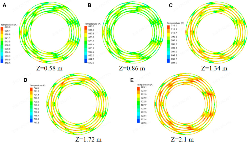
FIGURE 12. Temperature on the vertical section of the shell side of OTSG. (A) Z=0.58 m. (B) Z=0.86 m. (C) Z=1.34 m. (D) Z=1.72 m. (E) Z=2.1 m.
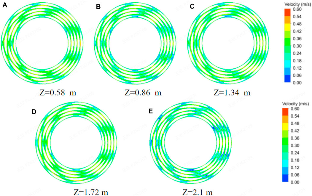
FIGURE 13. Velocity on the vertical section of the shell side of OTSG. (A) Z=0.58 m. (B) Z=0.86 m. (C) Z=1.34 m. (D) Z=1.72 m. (E) Z=2.1 m.
This type of OTSG prototype contains a total of five layers of heat transfer tubes. Due to the internal resistance of the tube bundle and the different heat transfer boundaries between the inside and outside of the tubes, the power of the heat transfer tubes in each layer may be different. The flow rate, outlet steam temperature, and total heat transfer power of each layer of heat transfer tubes are calculated, as shown in Table 4. The outlet steam temperature of each layer of heat transfer tubes is the same, but because the number of heat transfer tubes in the outermost layer is greater than that in the inner layer, the total power of the outer layer tubes is greater than that of the innermost layer. However, on average for each heat transfer tube, there is little difference in flow rate and heat transfer power between the inner tube and the outer tube.

Figures 14–16 show the axial distribution of the average temperature of the outer wall of the heat transfer tubes, the heat flux of the outer wall of the tube, and the quality in the tubes. The heat flux density changes significantly with the flow phase change in the tube side. It can be seen from the figure that the difference in the average temperature of the outer wall of the heat transfer tubes of different layers is small, there is a significant difference in heat flux between heights of about 0.5–1.7 m, but this difference in heat flux has little impact on the outlet gas content.

FIGURE 14. Average temperature of the outer wall of the heat transfer tubes.
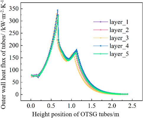
FIGURE 15. Heat flux of the outer wall of the tube.
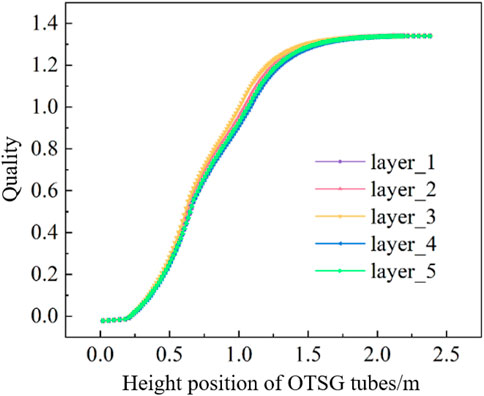
FIGURE 16. Quality in the tubes.
In this paper, a flow heat transfer model was developed that couples a 1D system code and a 3D CFD software by building a coupling surface to transfer heat flux density on the outer wall of the OTSG helically coiled tubes. The overall flow heat transfer characteristics of a prototype OTSG are analyzed. The main conclusions are as follows:
1) For the fluid inside the OTSG helically coiled tubes, use LOCUST to establish a 1D parallel multi-channel model to simulate its complex two-phase flow heat transfer. For the single-phase flow and heat transfer characteristic outside the tubes, use FLUENT to analyze by 3D simulation. A coupled heat transfer model inside and outside the tube is built through spatial mapping, and the wall heat flux calculated by LOCUST is transferred to FLUENT for 3D simulation, thereby obtaining the 3D distribution characteristics of the flow and heat transfer characteristics inside and outside the OTSG helically coiled tubes. This coupling method can obtain a high-resolution single-phase fluid flow field and temperature field outside the tubes while ensuring accurate simulation of complex two-phase flow heat transfer in the tubes. After comparing with the experimental data, the error of the heat flux calculated by the coupled model is within 15%.
2) During the steady-state calculation process, if the given initial wall temperature is lower than the actual value, the program calculation convergence will be accelerated, otherwise, the program will be more likely to diverge. Therefore, it is necessary to relax the outer wall temperature of the helically coiled tubes to avoid failure to converge due to temperature and heat flow data oscillation in the coupled calculation. The selection of the convergence factor and the type of boundary conditions at the primary and tube side coupling boundaries will all have an impact on the convergence efficiency of the coupling program.
3) In the coupling simulation of the OTSG prototype, the shell side temperature field gradually decreases along the flow direction, the inlet-outlet temperature difference is as high as 150°C, and the unevenness of the radial temperature distribution increases along the flow direction. In addition, the wake swing effect caused by the sweeping flow of the tube bundle at the exit position is obvious. What needs to be noted in the design of OTSG is that large fluid temperature differences and possible temperature fluctuations will cause stress on the OTSG structural materials.
This research can provide support for the refined design and analysis of OTSG and has good application prospects in the analysis of heat transfer characteristics of OTSG.
The original contributions presented in the study are included in the article/supplementary material, further inquiries can be directed to the corresponding author.
WX: Writing–original draft, Writing–review and editing. LX: Supervision, Writing–review and editing. ZX: Formal analysis. CX: Validation. MS: Writing–review and editing. RT: Data curation, Writing–review and editing. CJ: Writing–review and editing. MY: Writing–review and editing. HY: Writing–review and editing. SC: Writing–review and editing.
The author(s) declare financial support was received for the research, authorship, and/or publication of this article. National Natural Science Foundation of China Joint Fund Project (U20B2011).
Authors WX, LX, ZX, CX, MS, RT, CJ, MY, HY, and SC were employed by China Nuclear Power Technology Research Institute Co., Ltd.
All claims expressed in this article are solely those of the authors and do not necessarily represent those of their affiliated organizations, or those of the publisher, the editors and the reviewers. Any product that may be evaluated in this article, or claim that may be made by its manufacturer, is not guaranteed or endorsed by the publisher.
Bjornard, T. A., and Griffith, P. (1977). “PWR blowdown heat transfer,” in Thermal and hydraulic aspects of nuclear reactor safety. Vol. I.
Chen, H. D., Chen, J. Y., and Zhang, X. Y. (2019). Development of thermal-hydraulic analysis code of a helically coiled once-through steam generator based on two-fluid model. Ann. Nucl. Energy 132, 773–783. doi:10.1016/j.anucene.2019.06.047
Chen, J. C. (1966). Correlation for boiling heat transfer to saturated fluids in convective flow. Industrial Eng. Chem. process Des. Dev. 5, 322–329. doi:10.1021/i260019a023
Choe, W., Weinberg, L., and Weisman, J. (1978). Observation and correlation of flow pattern transitions in horizontal, cocurrent gas-liquid flow. Two Phase Transp. React. Saf., 1357–1375.
Colombo, M., Colombo, L. P., Cammi, A., and Ricotti, M. E. (2015). A scheme of correlation for frictional pressure drop in steam–water two-phase flow in helicoidal tubes. Chem. Eng. Sci. 123, 460–473. doi:10.1016/j.ces.2014.11.032
De Schepper, S. C., Heynderickx, G. J., and Marin, G. B. (2008). CFD modeling of all gas–liquid and vapor–liquid flow regimes predicted by the Baker chart. Chem. Eng. J. 138, 349–357. doi:10.1016/j.cej.2007.06.007
Etghani, M. M., and Baboli, S. a.H. (2017). Numerical investigation and optimization of heat transfer and exergy loss in shell and helical tube heat exchanger. Appl. Therm. Eng. 121, 294–301. doi:10.1016/j.applthermaleng.2017.04.074
Friedel, L. (1979). “Improved friction pressure drop correlations for horizontal and vertical two-phase pipe flow,” in European two-phase group meeting, Ispra, Italy, June 5 - June 8, 1979.
Griffith, P., and Wallis, G. B. (1961). Two-phase slug flow. J. Heat Transf. 83, 307–318. doi:10.1115/1.3682268
Hewitt, G. (1977). “Two-phase flow patterns and their relationship to two-phase heat transfer,” in Two-phase flows and heat transfer, Vol. 1.
Heydari, O., Miansari, M., Arasteh, H., and Toghraie, D. (2021). Optimizing the hydrothermal performance of helically corrugated coiled tube heat exchangers using Taguchi’s empirical method: energy and exergy analysis. J. Therm. Analysis Calorim. 145, 2741–2752. doi:10.1007/s10973-020-09808-3
Huang, J., Gou, J. L., Mao, H. H., and Shan, J. Q. (2020). Development of a thermal -hydraulic analysis code for helically coiled once-through steam generator. Nucl. Eng. Des. 364, 110642. doi:10.1016/j.nucengdes.2020.110642
Jiaqiang, E., Zhao, X., Deng, Y., and Zhu, H. (2016). Pressure distribution and flow characteristics of closed oscillating heat pipe during the starting process at different vacuum degrees. Appl. Therm. Eng. 93, 166–173. doi:10.1016/j.applthermaleng.2015.09.060
Jo, J. C., Kim, W. S., Choi, C.-Y., and Lee, Y. K. (2009). Numerical simulation of subcooled flow boiling heat transfer in helical tubes.
Kim, S.-M., Jo, J.-H., Lee, Y.-E., and Yoo, Y.-S. (2016). Comparative study of shell and helically-coiled tube heat exchangers with various dimple arrangements in condensers for odor control in a Pyrolysis System. Energies 9, 1027. doi:10.3390/en9121027
Mansour, M., Landage, A., Khot, P., Nigam, K. D., Janiga, G. B., TheVenin, D., et al. (2019). Numerical study of gas–liquid two-phase flow regimes for upward flow in a helical pipe. Industrial Eng. Chem. Res. 59, 3873–3886. doi:10.1021/acs.iecr.9b05268
Mirgolbabaei, H. (2018). Numerical investigation of vertical helically coiled tube heat exchangers thermal performance. Appl. Therm. Eng. 136, 252–259. doi:10.1016/j.applthermaleng.2018.02.061
Niu, X., Luo, S., Fan, L.-L., and Zhao, L. (2016). Numerical simulation on the flow and heat transfer characteristics in the one-side heating helically coiled tubes. Appl. Therm. Eng. 106, 579–587. doi:10.1016/j.applthermaleng.2016.05.167
Prattipati, R., Pendyala, S., and Prasad, B. (2021). Void fraction in helical coils during flow boiling with inlet subcooling. Int. J. Heat Mass Transf. 168, 120904. doi:10.1016/j.ijheatmasstransfer.2021.120904
Radovcich, N. A. (1962). The transition from two phase bubble flow to slug flow. Massachusetts: Massachusetts Institute of Technology.
Saha, S. K., Ranjan, H., Emani, M. S., and Bharti, A. K. (2022). Two-phase heat transfer enhancement. Cham: Springer.
Seban, R., and Mclaughlin, E. (1963). Heat transfer in tube coils with laminar and turbulent flow. Int. J. heat mass Transf. 6, 387–395. doi:10.1016/0017-9310(63)90100-5
Sun, B., Yu, X., Liu, S., Shi, J., Yang, L., Zhang, G., et al. (2018). Non-uniform wall temperature distribution of nucleate boiling heat transfer in helically coiled tubes. Nucl. Eng. Des. 330, 356–367. doi:10.1016/j.nucengdes.2018.02.014
Xie, L., Xie, Y., and Yu, J. (2015). Phase distributions of boiling flow in helical coils in high gravity. Int. J. Heat Mass Transf. 80, 7–15. doi:10.1016/j.ijheatmasstransfer.2014.08.094
Xu, P., Zhou, T., Xing, J., Chen, J., and Fu, Z. (2022). Numerical investigation of heat-transfer enhancement in helically coiled spiral grooved tube heat exchanger. Prog. Nucl. Energy 145, 104132. doi:10.1016/j.pnucene.2022.104132
Xu, Z., Liu, M., Xiao, Y., and Gu, H. (2021). Development of a RELAP5 model for the thermo-hydraulic characteristics simulation of the helically coiled tubes. Ann. Nucl. Energy 153, 108032. doi:10.1016/j.anucene.2020.108032
Yang, Z., Peng, X., and Ye, P. (2008). Numerical and experimental investigation of two phase flow during boiling in a coiled tube. Int. J. Heat Mass Transf. 51, 1003–1016. doi:10.1016/j.ijheatmasstransfer.2007.05.025
Yao, H., Chen, G., Lu, K., Liao, H., Wu, Y., Tian, W., et al. (2021). Study on the thermal and geometrical parameters of helical coil once-through steam generator system. Int. J. Adv. Nucl. React. Des. Technol. 3, 80–96. doi:10.1016/j.jandt.2021.07.001
Keywords: once-through steam generator (OTSG, ), coupling model, three-dimensional flow and heat transfer, shell and tube side coupling, parallel multi-channel
Citation: Lu X, Wang X, Zheng X, Chen X, Meng S, Ruan T, Chen J, Mao Y, Hu Y and Shang C (2024) Development and preliminary verification of a 1D–3D coupled flow and heat transfer model of OTSG. Front. Energy Res. 12:1368303. doi: 10.3389/fenrg.2024.1368303
Received: 10 January 2024; Accepted: 26 January 2024;
Published: 16 February 2024.
Edited by:
Yuze Sun, Northwestern Polytechnical University, ChinaReviewed by:
Taiyang Zhang, University of Illinois at Urbana-Champaign, United StatesCopyright © 2024 Lu, Wang, Zheng, Chen, Meng, Ruan, Chen, Mao, Hu and Shang. This is an open-access article distributed under the terms of the Creative Commons Attribution License (CC BY). The use, distribution or reproduction in other forums is permitted, provided the original author(s) and the copyright owner(s) are credited and that the original publication in this journal is cited, in accordance with accepted academic practice. No use, distribution or reproduction is permitted which does not comply with these terms.
*Correspondence: Xin Wang, a2FzaW01NkAxNjMuY29t
Disclaimer: All claims expressed in this article are solely those of the authors and do not necessarily represent those of their affiliated organizations, or those of the publisher, the editors and the reviewers. Any product that may be evaluated in this article or claim that may be made by its manufacturer is not guaranteed or endorsed by the publisher.
Research integrity at Frontiers
Learn more about the work of our research integrity team to safeguard the quality of each article we publish.