 Tianqin Lin1
 Hebin Liao
 Zhixiong Li
- 1Longyan Tobacco Industry Co., Ltd., Longyan, China
- 2Department of Electronics Engineering, Faculty of Electrical and Electronics Engineering, Kaunas University of Technology, Kaunas, Lithuania
- 3Department of Manufacturing Engineering and Automation Products, Opole University of Technology, Opole, Poland
To address the issue of high NOx emission from the combustion chamber, this work optimized the industrial machine structure to enhance the combustion performance. The analysis results indicated that the flue gas recirculation (FGR) could effectively reduce the combustion temperature and the distribution of high-temperature regions in the machine chamber, thereby suppressing NOx formation without affecting the gas velocity inside the chamber. Based on the simulation analysis, the FGR technology was applied to modifying the machine structure and evaluated the modification effect in real-world application. It is found that after adding FGR, the oxygen content at the furnace outlet decreased from 13.8% to 10.5%, the NOx emission from the furnace decreased from 80 mg/m3 to 18 mg/m3, and the natural gas consumption decreased by more than 17%. These results demonstrate a significant impact on energy saving and emission reduction after optimizing the machine structure, which can provide a reference basis for subsequent researchers in this field.
1 Introduction
Combustion furnaces are essential machines for many industrial applications. However, they generate large amounts of nitrogen oxides (NOx) emissions during operation, and require high excess air ratios to ensure complete combustion and sufficient heat supply. Conventional tobacco combustion furnaces rely on direct methane combustion, which leads to high-temperature and oxygen-rich conditions that favor NOx formation. NOx is a major air pollutant that can cause various environmental and health problems, such as acid rain, smog, ozone depletion and respiratory diseases (Li et al., 2024). Moreover, high-temperature and oxygen-rich conditions result in more energy waste. Therefore, reducing NOx emissions and methane consumption from tobacco furnaces is an urgent challenge.
Many researchers have developed various low-NOx combustion technologies to reduce NOx emissions (Zhou et al., 2024). These technologies mainly include flue gas recirculation technology, staged combustion technology, oxy-combustion technology, flameless combustion technology and low-nitrogen burner technology (Wu et al., 2020; Abubakar et al., 2021; Ouyang et al., 2021; Liu et al., 2023; Li et al., 2023). Among these, FGR technology is widely used, which is based on the principle of feeding low-temperature flue gases from the end of the combustion furnace into the combustion air, and the combustion air is fully mixed to participate in combustion. This can effectively reduce the volume fraction of oxygen in the combustion air, thereby reducing the mixing of the initial combustion intensity and furnace combustion temperature, and ultimately achieve the effect of reducing NOx formation in the furnace. Researchers have found that for a certain air mass flow rate, the average furnace temperature and NO concentration decrease as the excess air ratio increases (Emami et al., 2019; Ha, 2017). Experiments by Shinomori K et al. (2011) investigated a self-recirculating combustor where NOx emissions were significantly reduced with increasing flue gas recirculation rates and excess air ratios. Men Y et al. (2022) proposed a novel flue gas recirculation system for boiler retrofit. The results showed that NOx emissions were reduced by 82.3%, realizing ultra-low NOx emissions; for a 1.8 MW boiler, 7%–8% of natural gas consumption could be saved annually. Wang J. G. et al. (2019) obtained the oxidant content and flue gas content at different flue gas recirculation rates using thermal calculation and iterative calculation methods. He applied these data to the numerical simulation and found that as the flue gas recirculation rate increases, the maximum combustion temperature and NOx formation in the furnace decrease. Shi B. et al. (2018) investigated the effect of FGR on coal combustion and NO emissions in a boiler experimental system, followed by industrial tests on a chain boiler previously utilizing FGR. The data showed that FGR reduced NO emissions and incomplete combustion losses of gases. NO and CO emissions were reduced by 26.9% and 38%, respectively. However, excessive flue gas recirculation rate and excess air ratio will lead to incomplete combustion and increased heat loss (Liu et al., 2020; Sun et al., 2023). Therefore, researchers need to consider the effect of various factors on NOx formation in order to reduce NOx emissions at the root. Cho and Lee (2022) numerically investigated three recirculation methods in a methane-air countercurrent diffusion flame with flue gas dilution at the fuel (FIR), air (FGR), and both sides (FIR + FGR). The results show that fuel-side recirculation has a significant effect on the flame zone and is effective in reducing NO. Park M et al. (Park et al., 2017) used a laboratory scale downcomer to vary the flow and concentration of nitrogen (N2), carbon dioxide (CO2) and water vapour (H2O) of the recycled gas during combustion. They found that the influence of the recycled gas composition on the NOx concentration was not significant, and that the flue gas recirculation rate had a greater influence on the change in NOx concentration. Finally, the main reason for the reduction in NOx emissions is that the injection of recycled gas reduces the oxygen concentration and the maximum combustion temperature. Ren F et al. (2019) calculated the premixed combustion characteristics and NOx emission of CH4 using N2, CO2 and H2O as dilution gases. The results showed that the addition of N2, CO2 and H2O reduced the adiabatic flame temperature of CH4 and suppressed NO formation. Wang W et al. (2022) evaluated the flue gas recirculation (FGR) flue gas cleaning system of a waste incineration power plant. The concentrations of various pollutants were measured and compared with domestic and international standards. The results showed that FGR can effectively reduce NOx emissions, while the use of FGR can make the NOx emission concentration meet the national emission standards. Some researchers are also combining a variety of low nitrogen technologies to reduce NOx emissions. Abdelaal M et al. (2021) performed numerical simulations on a 20 kW test furnace using FGR technology and oxy-combustion technology. The results showed that at a flue gas recirculation rate of 40%, the flame is stable, but the flame temperature is reduced by about 25% and NOx is reduced from 90 ppm to 5 ppm. Zhu Y et al. (2021) designed a low-NOx burner for FGR gas boilers, using a non-mixed combustion method to reduce NOx emissions. The burner achieves low-temperature combustion, stable combustion and improves temperature uniformity, resulting in a significant reduction of NOx formation. The e-FGR rate can be as high as 40%, and the NO concentration at the boiler outlet is less than 30 mg/Nm3.
To the best of our knowledge, few works consider the application of FGR in tobacco industry, and it has several limitations. First, the tobacco industry is dominated by a small number of manufacturers who have a stronghold on the major equipment used in the industry. Due to the high cost of optimization and the limited number of cigarette factories around the world, these manufacturers tend to develop new equipment rather than optimizing the performance of existed equipment. In addition, the characteristics, combustion behavior, and sensitivity of tobacco pose a challenge for implementing FGR technology in the tobacco industry.
In conclusion, we used FGR technology to control the NOx and methane emissions from a tobacco combustion furnace. We controlled the maximum combustion temperature by adjusting the oxygen concentration without changing the combustion product flow rate, and then controlled the methane flow rate by tuning the methane flow and excess air ratio. For the combustion furnaces of different tobacco companies, the process conditions will be significantly different due to the different process involved. So, the relevant literature and technology can only provide technical references, but cannot provide universal conclusions. Based on this, this paper discusses the feasibility of flue gas recirculation technology for a tobacco company’s tobacco combustion furnace by using Fluent numerical simulation, performs structural optimization and implementation, and finally realizes the control of methane flow and NOx emissions.
The innovation point of this paper is to use the flue gas recirculation to confirm the optimization scheme of industrial field equipment, and then, guide the optimization transformation of industrial equipment. The biggest difference with laboratory structure optimization and real-world parameter optimization is that the actual field problems generated by the transformation of industrial equipment are more complex than that of laboratory testing, and more parameters are not measurable in real-world case. To our best knowledge, little work has been done to address this challenge in existing literature. We should emphasize that the technical feasibility verification and implementation of the developed method in this study will greatly promote the optimization of industrial equipment in energy efficiency and economy.
2 Materials and methods
2.1 Working principle of the combustion furnace system
The combustion furnace system mainly consists of compressed air pipe, fuel gas pipe, burner, heat exchanger, exhaust gas preheater and flue gas pipe. The system supplies natural gas and compressed air to the burner through the fuel gas pipe and compressed air pipe, which are ignited to generate heat. The heat is transferred to the heating medium through the heat exchanger and the waste heat is recovered through the exhaust gas preheater. Finally, the treated flue gas is released into the atmosphere through the flue gas pipe. The working principle of the combustion furnace is shown in Figure 1.
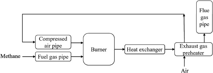
Figure 1. Schematic diagram of the working principle of the combustion furnace.
The various components of a combustion furnace system have different roles, which are explained as below:
(1) Compressed air pipe: The compressed air pipe is responsible for supplying com-pressed air to the combustion furnace.
(2) Fuel gas pipe: The fuel gas pipe is responsible for supplying fuel gas to the com-bustion furnace. The fuel gas can be natural gas, liquefied petroleum gas (LPG), gas, etc.
(3) Burner: The burner is the combustion part of the combustion furnace, responsible for mixing and burning the fuel gas and air.
(4) Heat exchanger: The heat exchanger is responsible for transferring the heat generated by combustion to the process fluid (such as water, air, etc.).
(5) Exhaust gas preheater: The exhaust gas preheater is responsible for transferring the heat carried by the flue gas discharged from the flue at the end of the furnace to the air before it enters the furnace, and for preheating the air to a certain temperature.
(6) Flue gas pipe: The flue gas pipe is responsible for discharging exhaust gases from the combustion furnace to the atmosphere.
2.2 Simulation scheme
The main process function of the tobacco combustion furnace is to provide a heat source for the process gas and to raise the process gas temperature to over 300°C. The furnace temperature is generally set at 660°C.
There are two commonly used technological methods in combustion systems: internal flue gas circulation and external flue gas circulation, which are used to improve combustion efficiency and control exhaust emissions. Internal flue gas recirculation recirculates a portion of the exhaust gases back into the combustion zone, while external flue gas recirculation reintroduces a portion of the products of combustion back into the combustion process.
Advantages of the internal flue gas recirculation technique include reduced nitrogen oxide (NOx) emissions, improved combustion efficiency, and a balanced combustion process. However, there are some limitations to this technology. Firstly, the structure and design of the combustion equipment needs to be considered to ensure that the internal recirculation flue gas is evenly distributed to the combustion zone to avoid adverse effects on the burner interior. Second, too high a proportion of internal recirculating flue gas may lead to an unstable combustion process with problems such as flame destabilization and flame extinguishing. In addition, internal recirculation flue gas can reduce NOx emissions but may increase carbon monoxide (CO) emissions, requiring a balance between the two.
In contrast, the external flue gas recirculation technology has the following characteristics: first, by reducing the temperature and oxygen concentration in the combustion region, NOx generation and emissions can be effectively reduced. Secondly, the heat energy carried in the external flue gas can be further utilized to improve combustion efficiency and reduce energy waste. In addition, by adjusting the flow rate and temperature of the externally circulating flue gas, precise control of the combustion process can be realized to meet different working conditions and requirements.
Figure 2 is the structure plan of the tobacco combustion furnace system, and Figure 3 is the structure plan view of the tobacco combustion furnace optimization system. It can be seen from the figures that the tobacco combustion furnace optimization system adopts the flue gas recirculation technology scheme. Specifically, an exhaust fan pipe is connected from the chimney to introduce the flue gas into the furnace for combustion. At the same time, a manual valve is installed on the new exhaust pipe. By manually adjusting the size of the valve, the oxygen content of the flue gas entering the furnace is ensured to ensure stable combustion of the furnace.
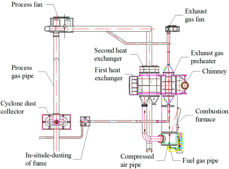
Figure 2. Plan view of the combustion furnace system structure.
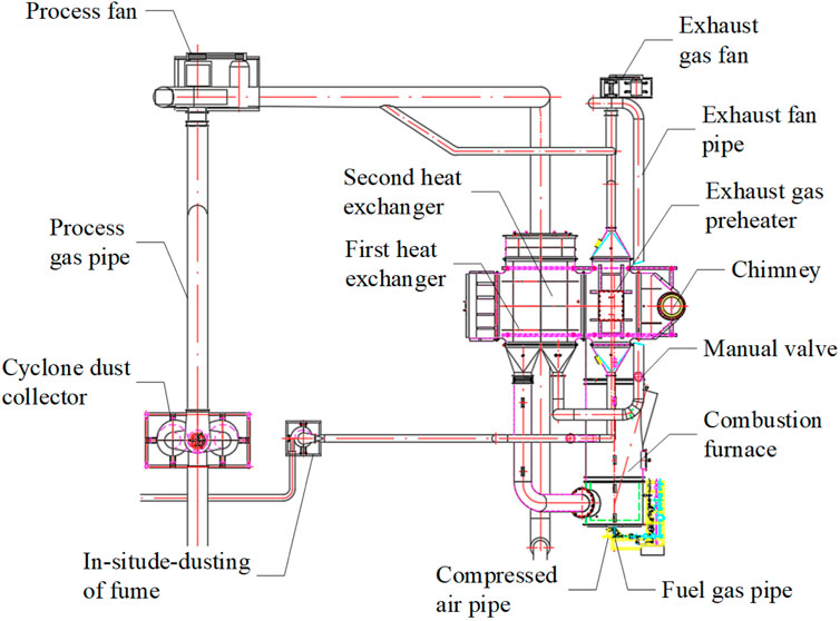
Figure 3. Plan view of the combustion furnace optimization system structure.
The structure of the system ultimately affects the excess air ratio. Therefore, we simplify the structure of the furnace optimization system and study the combustion characteristics of the furnace with the excess air ratio as the boundary condition. The structure of the furnace optimization system is shown in Figure 4.
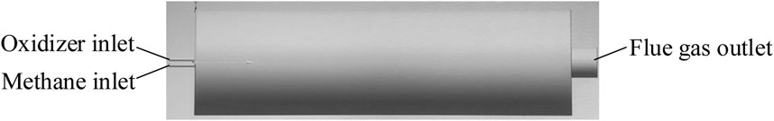
Figure 4. Calculation model for combustion furnace simulation.
The body of the combustion furnace is a circular cylinder with a diameter of 2100 mm × 8300 mm. ICEM is used for meshing. The meshing diagram of the simplified model is shown in Figure 5. The right side is the outlet of the discharged flue gas, and the left side is the inlet of oxidizer and methane. The oxidizer includes air and flue gas, and its components mainly include water vapor, carbon dioxide, a large amount of nitrogen, and a small amount of oxygen. The ratio of the mass flow rate of the recirculated flue gas to the oxidizer flow rate is called FGR rate. The boundary conditions set as shown in Table 1. The inlet temperature of the model is 303.15 K. The oxidizer flow rate is 0.35 kg/s and the methane flow rate is 0.0123 kg/s, with an outlet pressure of 0 Pa.

Figure 5. Mesh diagram of the computational model for combustion furnace simulation.

Table 1. Boundary conditions of model.
To simulate the operation process of the combustion furnace, the k-ε model was used as turbulence model. The interaction between turbulence and chemical reactions is simulated by the eddy dissipation model. The chemical reaction mechanism uses a two-step reaction of methane and air (methane-air-twostep). The formation of pollutants takes into account the thermal NOx and the prompt NOx.
To ensure the accuracy of the numerical simulation results, a mesh independence analysis was conducted. Taking the exit velocity as the verification parameter, the mesh independence results are shown in Figure 6. The mesh independence results show that when the number of meshes exceeds 1.28 million, the difference in the maximum velocity in the furnace is small. Therefore, the mesh number of 1.28 million was chosen for the subsequent model calculations.
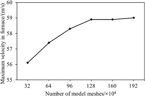
Figure 6. Comparison results of calculations with different number of meshes.
3 Simulation results and analysis
This paper adjusts the FGR rate to research its effect on the furnace velocity, combustion temperature and outlet NOx concentration. Based on the setting from Ref (Wang, 2019). and the actual temperature requirement of field (the average furnace temperature is 660°C, and the temperature decreases steadily as the flue gas content rises until combustion stops), the maximum value of the FGR rate is defined as 50%. In the simulation, six operation conditions are set with FGR rate of 0%, 10%, 20%, 30%, 40%, 50%, respectively. The state defined as a FGR rate of 0% corresponds to the original configuration of the combustion furnace.
3.1 Mathematical model
3.1.1 Turbulence model
Among the commonly used turbulence models, k-ε is most commonly used in engineering, where k in the k-ε model stands for the turbulence kinetic energy, ε stands for the dissipation rate, and the mathematical expression of the model is a two-sided equation consisting of k and ε in Equations 1, 2.
where, Gk is calculated by Equation 3:
3.1.2 Combustion model
The Eddy-Dissipation (ED) eddy dissipation model is a commonly used combustion model to describe the physical and chemical reactions of fuels during combustion. Most of the chemical reactions based on the Eddy-Dissipation model involve rapid combustion of the fuel, with the overall reaction rate controlled by turbulent mixing. In a non-premixed flame, turbulence slowly passes through the convective/mixed fuels and oxidizers into the reaction zone where they burn rapidly.
In the ED model, the net reaction rate Rir of component i in a chemical reaction r will be determined by the smaller value of Equations 4, 5:
where
3.1.3 NOx model
Two main types of nitrogen oxides (NOx) are produced when burning in a combustion furnace fueled with natural gas: thermal NOx and prompt NOx (Park, 2019). The formation principle of thermal NOx is that under high-temperatures, nitrogen (N2) and oxygen (O2) molecules react to form nitric oxide (NO). This process is called the thermal generation mechanism of thermal NOx. Subsequently, NO further reaction with O2 to form nitrogen dioxide (NO2). These NOx are one of the main pollutants produced in the combustion process.
Prompt NOx is formed at 900°C–1,300°C for a very short time, so it is called prompt NOx. The formation principle of prompt NOx is that during combustion, nitrogen (N2) in the air reacts with hydrocarbon ionic groups (CH, etc.) in the fuel to form CN compounds, which are then oxidized to NOx.
3.2 Velocity field
Under the normal working conditions of the combustion furnace, the velocity field of the central section of the combustion furnace model is calculated under different working conditions. The velocity field distribution in the furnace is shown in Figure 7, where (a∼f) represents the velocity field distribution with FGR rates of 0%, 10%, 20%, 30%, 40%, and 50%, respectively. It can be seen from the figure that, under different working conditions, the gas velocity gradually decreases with increasing distance from the inlet, but the maximum velocity in the furnace remains about 58.9 m/s. This is because, under different working conditions, the flow of oxidizer and natural gas at the inlet remains unchanged, but their components change so that the gas velocity is not affected.
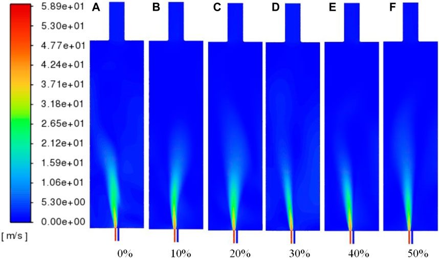
Figure 7. Distribution of velocity field cloud diagrams at different FGR rates: (A) 0% flue gas volume; (B) 10% flue gas volume; (C) 20% flue gas volume; (D) 30% flue gas volume; (E) 40% flue gas volume; (F) 50% flue gas volume.
3.3 Temperature field
The temperature field cloud distribution of the combustion furnace model under different working conditions is shown in Figure 8. From the figure, it can be seen that as the flue gas volume in the furnace increases, the combustion temperature decreases, the high-temperature region gradually decreases, and the temperature distribution in the furnace becomes more uniform. The main reason for this phenomenon is that the increase in the FGR rate leads to an increase in the flue gas volume in the furnace, which dilutes the oxygen concentration in the air. As the contact area between the fuel and the oxygen is reduced, the efficiency of the combustion reaction becomes lower, resulting in a lower combustion temperature in the furnace.
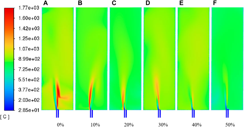
Figure 8. Temperature field cloud images at different FGR rates: (A) 0% flue gas volume; (B) 10% flue gas volume; (C) 20% flue gas volume; (D) 30% flue gas volume; (E) 40% flue gas volume; (F) 50% flue gas volume.
The relationship between FGR rate and the maximum combustion temperature is shown in Figure 9. With the increase of flue gas volume, the maximum combustion temperature decreases gradually. The maximum combustion temperatures were 1770°C, 1,634°C, 1,536°C, 1,347°C, 1,161°C and 1,069°C for FGR rate of 0%–50%.
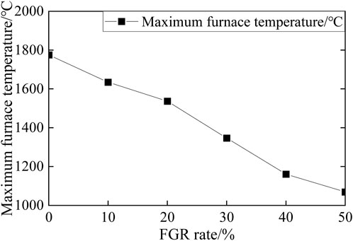
Figure 9. The relationship between FGR rate and maximum combustion temperature.
The relationship between the FGR rate and the average combustion temperature is shown in Figure 10. With the increase of flue gas volume, the average combustion temperature generally shows a decreasing trend. The average combustion temperatures of the furnace for FGR rates of 0%–50% are 827°C, 761°C, 722°C, 778°C, 747°C, and 637°C, respectively. It is particularly striking that the average temperature of the furnace with a FGR rate of 50% is closer to the furnace temperature required for close proximity to the actual process.
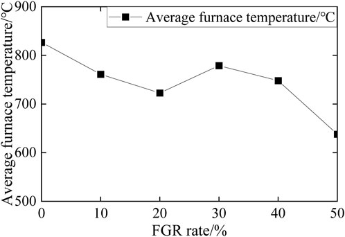
Figure 10. The relationship between FGR rate and average combustion temperature.
In conclusion, the application of flue gas recirculation technology in the combustion furnace can effectively reduce the combustion temperature in the furnace and reduce the distribution range of the high-temperature region. At the same time, it can make the temperature field in the furnace more uniform, so that the average temperature required in the furnace can be controlled. In addition, by comparing the maximum combustion temperature and the average combustion temperature in the original model furnace, it is found that the combustion furnace can reduce natural gas consumption when the average temperature required in the furnace is met.
3.4 NOx concentration field
The cloudy maps of NOx field at different FGR rates are shown in Figure 11. It can be seen that when the FGR rate increases from 0% to 10%, the NOx concentration in the furnace decreases significantly. However, between 10% and 50%, the change in concentration is not as noticeable because of the limited range of the color bar.
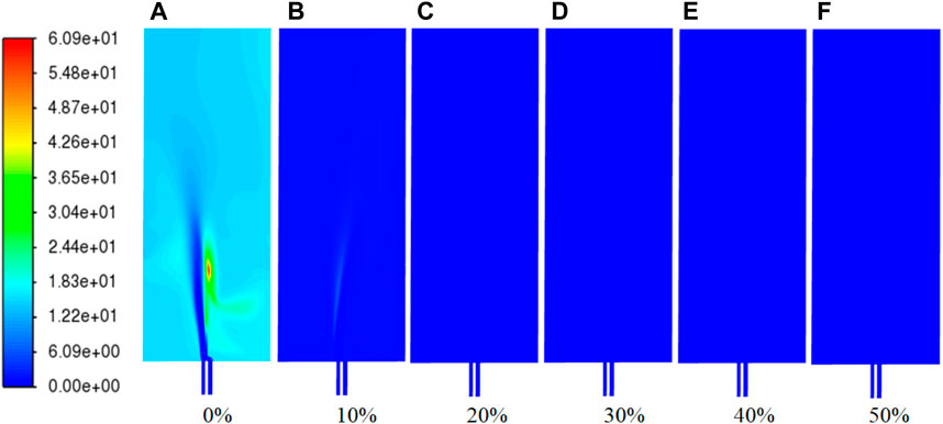
Figure 11. NOx field cloud distribution at different FGR rates: (A) 0% flue gas volume; (B) 10% flue gas volume; (C) 20% flue gas volume; (D) 30% flue gas volume; (E) 40% flue gas volume; (F) 50% flue gas volume.
Figure 12 shows the outlet O2 volume fraction and NOx concentration vary with the FGR rates. The x-axis represents the FGR rate (percentage), the left y-axis represents the outlet O₂ volume fraction (percentage), and the right y-axis represents the outlet NOx concentration (mg/m³). At the FGR rate is 0% (i.e., original combustion furnace), the O₂ volume fraction is about 8.22% and the NOx concentration is about 14.86 mg/m3. As the FGR rate increases from 0% to 10%, the NOx concentration decreased by 95%. This trend is consistent with the analysis of NOx distribution in Figure 11. When the FGR rate increases from 10% to 20%, the O₂ volume fraction and NOx concentration further decreases to 5.38% and 0.15 mg/m3. From 20% to 50% FGR rate, the O₂ volume fraction steadily decreases until it reaches 0%, and the change of NOx concentration is not obvious, eventually approaching 0 mg/m3.
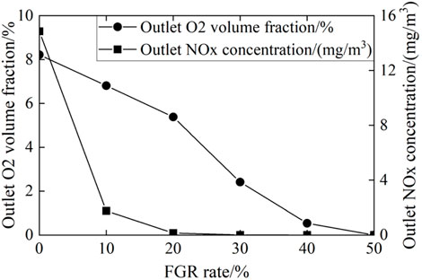
Figure 12. Variation of O2 volume fraction and NOx concentration with FGR rate.
With the FGR rate increases, both the outlet NOx concentration and the outlet O₂ volume fraction decrease significantly across the whole range. Especially the NOx concentration, which displays a noticeable change within the 0%–20% FGR rate range. This phenomenon can be explained by the fact that as the quantity of flue gas rises, the oxygen concentration in the furnace drops, leading to a reduction in the reaction rate of CH4 and O2. It decreases the combustion temperature of the furnace. In addition, oxygen deficiency reduces the reaction rate of N2 and O2, thereby significantly decreasing the production of thermal NO. Although the change in NOx concentration becomes less apparent at high FGR rates, the O₂ volume fraction continues to decrease, indicating further reduction in oxygen supply during combustion.
In conclusion, the implementation of FGR technology proves to be highly effective in reducing NOx emissions. Additionally, the control of furnace temperature provides a theoretical foundation for minimizing methane consumption.
4 Experimental verification
4.1 Combustion furnace transformation
Based on the simulation feasibility analysis results of the furnace optimization system, we conducted the structural transformation of the furnace. The transformation construction process is shown in Figure 13. We added a new pipe to return the flue gas to the exhaust fan and added a manual valve to the new exhaust fan pipe.
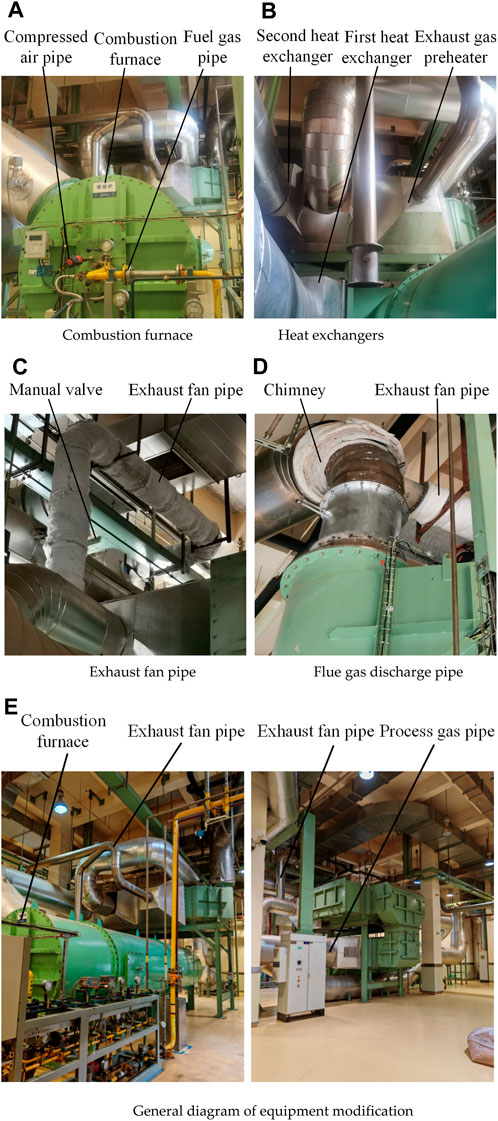
Figure 13. (A) Combustion furnace (B) Heat exchangers (C) Exhaust fan pipe (D) Flue gas discharge pipe (E) General diagram of equipment modification. Physical drawing of the modified combustion furnace optimization system.
4.2 Analysis of optimization results
A physical diagram of the oxygen content monitoring values at each critical point of the combustion furnace system before and after the modification at 50% FGR rate is shown in Figure 14.
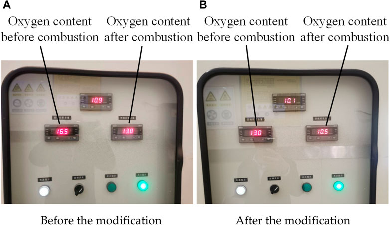
Figure 14. (A) Before the modification (B) After the modification. Physical diagram of oxygen content monitoring values at critical points of the combustion furnace system.
The zirconia oxygen analyzer model CY-CZ and temperature controller model P8010 was used to detect oxygen concentration and environment temperature during test. The major parameters of these equipment are shown in Table 2.
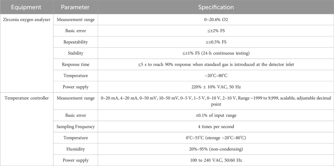
Table 2. Major parameters of detection equipment.
From the monitoring panel’s display values before and after the combustion furnace system transformation, it is evident that the oxygen content in the flue gas emitted from the furnace has significantly decreased following the transformation (average furnace temperature of 660°C). The oxygen content decreased from 13.8% before the modification to 10.5% after the modification. Additionally, the oxygen content in the oxidant has decreased from 16.5% before the transformation to 13.0% after the transformation. These changes indicate a significant reduction in the amount of fresh air injected, with the flue gas recirculation combustion playing a crucial role. As a result of the reduced oxygen content, the emission of nitrogen oxides has also significantly decreased. According to data from the company’s environmental protection department, the nitrogen oxide content decreased from 80 mg/m3 before the transformation to 18 mg/m3 after the transformation. Furthermore, based on natural gas consumption data from the tobacco company’s 1,140 expansion line in May and June 2023, there has been a 17% decrease compared to March and April 2023.
This paper uses the idea of flue gas recirculation to confirm the optimization scheme of industrial field equipment, and then guides the optimization transformation of industrial equipment. The biggest difference with laboratory structure optimization and process parameter optimization is that the actual field problems generated by the transformation of industrial equipment are more complex than that of laboratory testing, and more parameters are not measurable, but its technical feasibility verification and implementation will greatly promote the optimization of industrial equipment in energy efficiency and economy. According to the current calculation, the annual energy consumption will be saved by nearly 160,000 US dollars, and the environmental loss caused by emissions has not been calculated.
5 Conclusion
Tobacco combustion furnaces are notorious for their substantial nitrogen oxide (NOx) emissions and inefficiencies due to redundant methane and fresh air flows. In this study, we address these challenges by employing Fluent numerical simulation to explore the feasibility of Flue Gas Recirculation (FGR) technology in a tobacco company’s combustion furnace. Our investigation includes structural optimization and practical implementation, resulting in successful control of both methane flow and NOx emissions. Key findings from our simulation and experimental results are as follows:
(1) FGR Optimization: By integrating FGR technology, we transformed the combustion furnace. The NOx content at the furnace outlet decreased significantly, from 80 mg/m³ before the transformation to 18 mg/m³ afterward. Additionally, natural gas consumption reduced by 17% annually, and oxidizer fresh air content showed a marked decrease.
(2) Fluent Simulation Verification: We demonstrate the feasibility of using Fluent simulation technology to verify FGR effectiveness. This involved calculating the temperature field within the furnace, assessing NOx emissions, and determining the optimal FGR rate ratio based on process boundary conditions.
The work in this paper provides a theoretical and practical basis for energy saving and emission reduction in combustion furnaces. Moving forward, it is imperative to further investigate the implementation of our findings in different combustion furnaces, ensuring successful technology transplantation. Additionally, we propose exploring the potential synergies between our approach and the cold-end system of dry ice expanded tobacco production lines to maximize waste heat utilization. These future endeavors will lead us towards more comprehensive solutions for energy efficiency and emission reduction in various industrial processes.
Data availability statement
The raw data supporting the conclusions of this article will be made available by the authors, without undue reservation.
Author contributions
TL: Data curation, Formal Analysis, Investigation, Methodology, Writing–original draft. QC: Data curation, Formal Analysis, Funding acquisition, Resources, Software, Writing–original draft. SH: Investigation, Methodology, Project administration, Resources, Validation, Writing–original draft. WZ: Data curation, Formal Analysis, Investigation, Resources, Writing–original draft. HL: Conceptualization, Data curation, Formal Analysis, Funding acquisition, Writing–original draft. DA: Data curation, Methodology, Supervision, Validation, Writing–review and editing. ZL: Conceptualization, Funding acquisition, Supervision, Writing–review and editing.
Funding
The author(s) declare that the financial support was received for the research, authorship, and/or publication of this article. This research was funded by the Longyan Tobacco Industry Co. Ltd. under grant LC020301004. The research leading to these results has received funding from the National Science Centre, Poland under project no. 2023/51/B/ST8/02275. The funder was not involved in the study design, collection, analysis, interpretation of data, the writing of this article, or the decision to submit it for publication.
Acknowledgments
Great thanks are given to for providing the experimental design and data analysis suggestions from Munish Kamar Gupta.
Conflict of interest
Authors TL, QC, SH, WZ, and HL were employed by Longyan Tobacco Industry Co., Ltd.
The remaining authors declare that the research was conducted in the absence of any commercial or financial relationships that could be construed as a potential conflict of interest.
The author(s) declared that they were an editorial board member of Frontiers, at the time of submission. This had no impact on the peer review process and the final decision.
Publisher’s note
All claims expressed in this article are solely those of the authors and do not necessarily represent those of their affiliated organizations, or those of the publisher, the editors and the reviewers. Any product that may be evaluated in this article, or claim that may be made by its manufacturer, is not guaranteed or endorsed by the publisher.
References
Abdelaal, M., El-Riedy, M., El-Nahas, A. M., and El-Wahsh, F. R. (2021). Characteristics and flame appearance of oxy-fuel combustion using flue gas recirculation. Fuel 297, 120775. doi:10.1016/j.fuel.2021.120775
Abubakar, Z., Mokheimer, E. M. A., and Kamal, M. M. (2021). A review on combustion instabilities in energy generating devices utilizing oxyfuel combustion. Int. J. Energy Res. 45 (12), 17461–17479. doi:10.1002/er.7010
Cho, S. H., and Lee, K. M. (2022). Comparison of NO emission with flue gas recirculation methods in preheated air condition. J. Korean Soc. Combust. 27 (4), 1–10. doi:10.15231/jksc.2022.27.4.001
Emami, M. D., Shahbazian, H., and Sunden, B. (2019). Effect of operational parameters on combustion and emissions in an industrial gas turbine combustor. J. Energy Resour. Technol. 141 (1), 012202. doi:10.1115/1.4040532
Ha, J. S. (2017). A study on the combustion flow characteristic and NOx reduction of the exhaust gas recurculation burner using coanda nozzles. J. Korean Inst. Gas 21 (3), 53–60. doi:10.7842/kigas.2017.21.3.53
Li, H., Yao, Y., Zhang, G., Zhang, Z., Ying, J., Kong, L., et al. (2023). Experimental study on NOX formation characteristics in flue gas recirculation combustion process of S-CO2 coal-fired boiler. Combust. Sci. Technol., 1–16. doi:10.1080/00102202.2023.2249218
Li, H., Zheng, B., Lei, Y., Hauglustaine, D., Chen, C., Lin, X., et al. (2024). Trends and drivers of anthropogenic NO emissions in China since 2020. Environ. Sci. Ecotechnology 21, 100425. doi:10.1016/j.ese.2024.100425
Liu, J., Luo, X., Yao, S., Li, Q., and Wang, W. (2020). Influence of flue gas recirculation on the performance of incinerator-waste heat boiler and NOx emission in a 500 t/d waste-to-energy plant. Waste Manag. 105, 450–456. doi:10.1016/j.wasman.2020.02.040
Liu, Y., Zhao, Y., Zhang, L., Wu, J., Feng, J., Zhou, C., et al. (2023). Experiment and numerical study on combustion characteristics of low-nitrogen burners. Fuel 351, 128814. doi:10.1016/j.fuel.2023.128814
Men, Y., Liu, X., and Zhang, T. (2022). Performance research and application of the vapor pump boiler equipped with flue gas recirculation system. Energy Convers. Manag. 254, 115201. doi:10.1016/j.enconman.2021.115201
Ouyang, Z., Ding, H., Liu, W., Li, S., and Cao, X. (2021). Effect of the staged secondary air on NO emission of pulverized semi-coke flameless combustion with coal preheating technology. Fuel 291, 120137. doi:10.1016/j.fuel.2021.120137
Park, M., Shim, S. H., Jeong, S. H., Oh, K. J., and Lee, S. S. (2017). Nitrogen oxides emissions from the MILD combustion with the conditions of recirculation gas. J. Air and Waste Manag. Assoc. 67 (4), 402–411. doi:10.1080/10962247.2016.1234420
Park, S. (2019). Pressure effect on NO emission in methane/air lean-premixed flames. J. Mech. Sci. Technol. 33, 3031–3038. doi:10.1007/s12206-019-0553-1
Ren, F., Xiang, L., Chu, H., Jiang, H., and Ya, Y. (2019). Modeling study of the impact of blending N2, CO2, and H2O on characteristics of CH4 laminar premixed combustion. Energy and Fuels 34 (2), 1184–1192. doi:10.1021/acs.energyfuels.9b02108
Shi, B., Hu, J., Peng, H., and Ishizuka, S. (2018). Effects of internal flue gas recirculation rate on the NO emission in a methane/air premixed flame. Combust. Flame 188, 199–211. doi:10.1016/j.combustflame.2017.09.043
Shinomori, K., Katou, K., Shimokuri, D., and Ishizuka, S. (2011). NO emission characteristics and aerodynamic structure of a self-recirculation type burner for small boilers. Proc. Combust. Inst. 33 (2), 2735–2742. doi:10.1016/j.proci.2010.06.093
Sun, K., Liu, X., Ao, T., Liu, L., and Liang, Z. (2023). Experiment and numerical simulation study of low-nitrogen combustion technology inside small gas boiler. J. Energy Resour. Technol. 145 (10). doi:10.1115/1.4062871
Wang, J. G. (2019). Study on low nitrogen combustion characteristics of gas injection boiler based on flue gas recirculation. Xinjiang, China: Xinjiang University.
Wang, W., Tian, S., Long, J., Liu, J., Ma, Q., Xu, K., et al. (2022). Investigation and evaluation of flue gas pollutants emission in waste-to-energy plant with flue gas recirculation. Atmosphere 13 (7), 1016. doi:10.3390/atmos13071016
Wu, J., Zhao, K., Li, X., Wang, M., and Ni, S. (2020). Numerical study on staged combustion technology in burner of gas-fired boiler. Energy Sources, Part A Recovery, Util. Environ. Eff., 1–14. doi:10.1080/15567036.2020.1808741
Zhou, F., Yu, J., Wu, C., Fu, J., Liu, J., and Duan, X. (2024). The application prospect and challenge of the alternative methanol fuel in the internal combustion engine. Sci. Total Environ. 913, 169708. doi:10.1016/j.scitotenv.2023.169708
Keywords: industrial machines, combustion optimization, energy saving, emission reduction, optimization
Citation: Lin T, Cao Q, Huang S, Zhang W, Liao H, Andriukaitis D and Li Z (2024) Industrial equipment optimization for combustion performance enhancement: a real-world case study. Front. Energy Res. 12:1364538. doi: 10.3389/fenrg.2024.1364538
Received: 02 January 2024; Accepted: 12 August 2024;
Published: 26 August 2024.
Edited by:
Cong Qi, China University of Mining and Technology, ChinaReviewed by:
Sen Li, Institute of Mechanics, Chinese Academy of Sciences (CAS), ChinaFeng Zhou, Central South University Forestry and Technology, China
Copyright © 2024 Lin, Cao, Huang, Zhang, Liao, Andriukaitis and Li. This is an open-access article distributed under the terms of the Creative Commons Attribution License (CC BY). The use, distribution or reproduction in other forums is permitted, provided the original author(s) and the copyright owner(s) are credited and that the original publication in this journal is cited, in accordance with accepted academic practice. No use, distribution or reproduction is permitted which does not comply with these terms.
*Correspondence: Zhixiong Li, emhpeGlvbmcubGlAeW9uc2VpLmFjLmty