 Congshan Li
 Xiaowei Zhang
 Ping He
 Kefeng Zhao1
- 1College of Electrical and Information Engineering, Zhengzhou University of Light Industry, Zhengzhou, China
- 2Henan Xuji Instrument Co. Ltd., Xuchang, China
Droop control is widely used in multi-terminal flexible DC (VSC-MTDC) transmission systems by virtue of the advantage of multi-station cooperative unbalanced power dissipation, however, the essence of the droop control strategy is to change the DC current to realize the unbalanced power dissipation, and the resulting DC voltage deviation will affect the normal operation of the system. Firstly, this paper theoretically analyses the working characteristics of the conventional droop control and proposes a control method to realize the quasi-differential-free regulation of DC voltage by translating the droop curve. Second, according to the power margin of the converter station, the feedforward compensation amount of each converter station is reasonably set to avoid the power impact on the converter station. Finally, for the problem that the actual value of DC voltage still deviates from the rated value, a control strategy containing secondary regulation of DC voltage is proposed to further restore the DC voltage to the initial value on the basis of ensuring the effect of power regulation, which improves the stability of the operation of the VSC-MTDC system. The final simulation results verify the effectiveness of the proposed method.
1 Introduction
Compared to the line-commutated converter based multi-terminal direct current (LCC-MTDC) in traditional direct current grids, the voltage source converter based multi-terminal flexible direct current transmission (VSC-MTDC) system, which connects multiple converters through direct current lines, has gained extensive use due to independent control of active and reactive power, and flexible control of tidal currents (Wang et al., 2021; Ma et al., 2022; Yang et al., 2022). Droop control can take advantage of the power regulation capability of multiple converter stations simultaneously to absorb unbalanced power, which is widely used in VSC-MTDC systems. However, an obvious drawback of droop control is that it inevitably leads to DC voltage deviation while absorbing unbalanced power at converter stations, which negatively affects the stable operation of the system (Wang et al., 2020; Li et al., 2022).
Aiming to address the inherent DC voltage deviation issue arising from the use of conventional droop control for eliminating unbalanced power at converter stations, academia has proposed three improvement approaches. The first method involves achieving rational distribution of unbalanced power and mitigating DC voltage deviation by improving the droop coefficient. Refs (Liu et al., 2020; He et al., 2023; Wang et al., 2023). propose various adaptively adjusted droop control methods to suppress DC voltage deviation through the adjustment of the droop coefficient. However, after the completion of the dynamic regulation process, the converter station still experiences a deviation in active power and DC voltage. Furthermore, the aforementioned control method is highly dependent on the droop coefficient; a larger calculated droop coefficient may result in a smaller power fluctuation, yet cause a larger DC voltage deviation, ultimately impacting the overall stability of the system. If the calculated droop coefficient is small, it indicates greater active power distribution capability with a lower likelihood of power fluctuation, however, the DC voltage regulation capability is comparatively weak. Hence, the accuracy of the droop coefficient is crucial when implementing the above control method.
The second method involves overlaying the deviation of the DC voltage onto the droop control and continually optimizing the active power reference to reduce the DC voltage deviation. Refs (Fu Y. et al., 2021; Yu et al., 2022). respectively superimpose the DC voltage deviation onto the active power reference value to achieve non-error DC voltage regulation. However, the essence of the above methods is to transform the droop control station into a DC voltage control station, which loses the advantage of droop control for cooperative unbalanced power dissipation by multiple stations.
The third method is to adjust the active power value of the converter station proactively to achieve quasi non-error DC voltage regulation by shifting the droop curve. Refs (Zhu et al., 2018; Li et al., 2019a). gather the unbalanced power of the DC system, overlay it onto the reference value of active power at the converter station, and shift the droop curve during the dynamic regulation process for quasi non-error DC voltage regulation. The above control method solves the problem that the second control method loses the droop control multi-station coordinated consumption of unbalanced power. However, when the system returns to a stable state, there is still a deviation between the actual value of the DC voltage and the initial value, and the distribution of unbalanced power is not effectively controlled.
Aiming at the problems existing in the above control methods, this paper proposes an improved multi-point DC voltage coordinated control strategy based on the third method. Additionally, to tackle the problem of deviation in actual DC voltage values from the initial value, the paper suggests a control approach incorporating secondary DC voltage regulation, which continually corrects the DC voltage to its initial value. The primary focus of this paper encompasses the following aspects:
(1) An improved coordinated control strategy for multipoint DC voltage is proposed to achieve quasi non-error DC voltage regulation by injecting the unbalanced power as a feed-forward compensation quantity into the droop control.
(2) A power balance allocation scheme is proposed, which uses the available power margin of the converter station to reasonably allocate the unbalanced power of the system, to avoid the problem that the converter station with a smaller power margin is full and other converter stations still have power margin.
(3) A control method with secondary regulation of the DC voltage is proposed, where after the dynamic adjustment process of the system is completed, the DC voltage is restored to the initial value by using the non-static error characteristics of the PI controller.
Finally, a five-terminal VSC-MTDC simulation model is established by PSCAD/EMTDC, and the simulation results verify the effectiveness of the proposed control strategy.
2 Conventional droop control voltage deviation analysis
2.1 VSC-MTDC system model and control principle
The five-terminal VSC-MTDC system’s structure is presented in Figure 1. VSC1∼VSC5 depict voltage-source type converter stations. The DC side is connected through a DC network in parallel, and the AC side is connected to its corresponding AC grid, and the resistance of the lines between converter stations is 0.25 Ω.

FIGURE 1. VSC-MTDC system structure diagram.
Analogous to the primary frequency regulation characteristics of a conventional generator, droop control avoids the reliance on inter-station communication and leverages the characteristic curves of DC voltage and active power to rapidly distribute unbalanced power and maintain stable control of DC voltage. Figure 2 illustrates the structure of the DC voltage-active power (Udc-Ps) controller.
where Udc and Udcref represent the measured and reference values of DC-side voltage, respectively; Ps and Psref represent the measured and reference values of the active power of the converter station, respectively; k is the droop coefficient; and e(t) is the PI controller input (Song et al., 2021; Xiong et al., 2022).
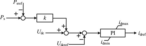
FIGURE 2. DC voltage droop Controller structure diagram.
When the system is in a stable state, the input of the PI controller is zero, and Eq. 1 can be simplified to:
2.2 Conventional droop control DC voltage deviation analysis
It is assumed that the DC system has N converter stations, of which 1∼m converter stations use conventional droop control; m+1∼n converter stations use constant active power control, and n+1∼N converter stations use constant AC voltage control.
The sum of the active power reference values of 1∼m droop stations Pr is
where 1 ≤ i ≤ m.
The sum of active power Pt of m+1∼n constant power stations is
where m+1 ≤ b ≤ n.
The sum of active power Pw of n+1∼N constant AC voltage converter stations is
where n+1 ≤ j ≤ N.
The conventional droop control operating curve is shown in Figure 3.
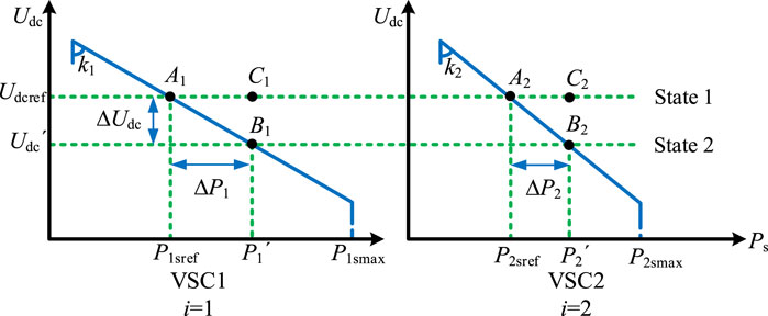
FIGURE 3. DC voltage droop control characteristic diagram.
According to Figure 3, at the initial steady state, the system should be operated in state 1. If a power disturbance, ΔP, occurs in the DC system, the m droop stations will use their own droop characteristics to dissipate the unbalanced power while the system operating point moves. When the steady state is reached again, the system is set to run in state 2 and the DC voltage deviation is ΔUdc. From Figure 3, it is apparent that the unbalanced power ΔPi borne by the droop station i has the following relationship with the DC voltage deviation ΔUdc.
According to the principle of energy conservation, the sum of the active power variation of each droop station should be equal to ΔP
Combining Eq. 6 with Eq. 7, we can obtain
From Eq. 8, it is apparent that ΔUdc is proportional to ΔP and inversely proportional to the sum of the reciprocals of the droop coefficients of m droop stations. This shows that when the power of the DC system fluctuates, all droop stations will cooperatively dissipate the unbalanced power according to their own droop curves (Li et al., 2019b; Liu et al., 2023).
From Eq. 9, it is evident that the droop coefficient determines how much unbalanced power is borne by the droop station in the dynamic regulation process. If each converter station adopts the same droop coefficient, all converter stations share the unbalanced power; if each converter station adopts different droop coefficients, converter stations with smaller droop coefficients will bear more unbalanced power, and converter stations with larger droop coefficients will bear less unbalanced power.
3 Improved coordinated control strategy for multi-point DC voltage
3.1 Improved droop control
Aiming at the DC voltage deviation problem inherent in the conventional droop control for dissipating the unbalanced power at the converter station, this paper proposes an improved coordinated control strategy for the multipoint DC voltage of the VSC-MTDC system, in which the unbalanced power is injected as a feed-forward compensation quantity into the droop control, and quasi non-error DC voltage regulation is realized by shifting the droop curve. The characteristic curve of the improved coordinated control strategy is shown in Figure 4.
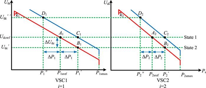
FIGURE 4. Improved coordinated control schematic.
Let the system be in state 1 at the initial steady state. When power disturbance ΔP occurs in the DC system, each droop station is given a feed-forward compensation amount of magnitude ΔPi, at this time, the stable operation point of the system is changed from Ai to Di to realize the flattening of the droop curve. Pisref and Pi'' are the reference values of active power before and after adjustment of the converter station, respectively, which satisfies
And then the converter station dissipates the unbalanced power according to the droop characteristic, and finally the system operates stably near the Ci point, realizing the quasi non-error DC voltage regulation. Compared with the conventional droop control, the active power transmitted by the converter station does not change, while the DC voltage deviation is approximately zero, and the stability of the system is greatly improved (Fu Q. et al., 2021; Liu Q. et al., 2022).
It is worth stating that when the DC network has a power surplus, the system DC voltage will increase, and under the improved droop control strategy in this paper, the droop curve will be shifted to the upper right, and the DC voltage will first rise and then fall to about the initial value. When the system has a power deficit, the system DC voltage decreases, and under the improved droop control strategy in this paper, the droop curve will level off to the lower left, and the DC voltage first decreases and then increases, and finally stabilizes at the initial value.
3.2 Power balance distribution program
To reasonably allocate the unbalanced power in the DC system to each droop station, this paper introduces the available power margin of the converter station to the power allocation coefficients and quickly adjusts the active power reference value. The power balance allocation scheme is shown in Eq. 11.
where Δt system sampling time. Under this power balance allocation scheme, the control system only needs to collect the active power value of the non-droop station, and update the active power reference value to the droop station when, and only when, the DC system current changes. In the rest of the cases, the droop station only needs to operate stably according to the latest updated active power reference value. At the same time, this power balance allocation scheme requires very low inter-station communication, and even when the communication of each converter station is interrupted, it can still operate normally according to the conventional droop control method.
3.3 DC voltage secondary regulation
According to the above analysis, the unbalanced power of the converter station is injected into the droop control as a feed-forward compensation quantity, and the quasi-differential-free regulation of the DC voltage can be realized by shifting the droop curve. However, when the system returns to the steady state again, the DC voltage deviation still exists, which is not conducive to the stable operation of the system. To address this problem, Res (Liu H. Y. et al., 2022) designs an additional DC voltage stabilizer with the control structure shown in Figure 5.
where ΔPrefu represents the value of additional power generated by the controller; ΔKu refers to the equivalent inertia coefficient; and ΔKv is the equivalent damping coefficient.
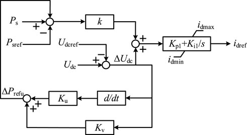
FIGURE 5. Additional DC voltage stabilizer structure.
Analogous to the synchronous generator inertia and damping, the controller takes ΔUdc as the input, and reduces the DC voltage deviation by adjusting the active power reference value during the power perturbation process. However, the DC voltage deviation is generally large in the early stage of power disturbance occurrence, and if ΔKu and ΔKv take larger values, it is easy to trigger overshooting of the converter station and generate power oscillations; if ΔKu and ΔKv take smaller values, the improvement of DC voltage is generally effective.
Aiming at the above problems, this section proposes an improved control method for the secondary regulation of DC voltage to restore the DC voltage to the initial value in case of slight changes in the active power of the converter station to realize the non-error DC voltage regulation. The structure of the improved DC voltage secondary regulation controller designed in this paper are shown in Figure 6 and Eq. (13):
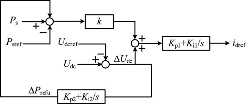
FIGURE 6. DC Voltage secondary regulation controller structure.
Similarly, the DC voltage secondary regulation controller takes ΔUdc as input and utilizes the steady state static-free characteristic of the PI controller to realize the static-free regulation of the DC voltage. Unlike the Res. (Liu H. Y. et al., 2022), the DC voltage secondary regulation controller does not have ΔKu and ΔKv parameters, so there is no need to worry about the influence of ΔKu and ΔKv values on the effect of improving the DC voltage. Meanwhile, to avoid the effect of ΔPrefu on the droop control at the early stage of the disturbance occurrence, the DC voltage secondary regulation controller can be operated again to restore the DC voltage to the initial value after some time of the improved droop control action in Section 3.1. Therefore, in this paper, the PI parameters for the droop control and the improved PI parameters for the DC voltage secondary regulation are set reasonably, Kp1 and Ki1 are set to 0.2 and 0.5 respectively, and Kp2 and Ki2 are set to 0.05 and 0.1 respectively. The step response times of the two PI controllers are differentiated to achieve the purpose of the successive response of the two controllers.
4 Simulation and analysis
In this paper, a five-terminal VSC-MTDC system as shown in Figure 1 is built based on PSCAD/EMTDC simulation software, and the specific simulation parameters are shown in Table 1.
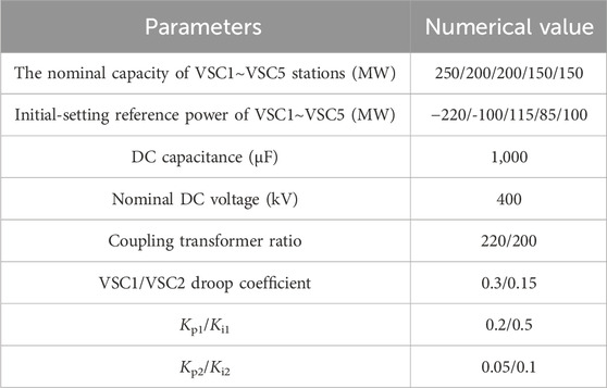
TABLE 1. Main parameters of the VSC-MTDC systems.
4.1 Validation of the effectiveness of an improved coordinated control strategy for multi-point DC voltage
To verify the effectiveness of the improved droop control strategy proposed in Section 3.1 of this paper, the comparative simulations set up in this section are as follows
Control Method 1 (CM1): conventional droop control; Control Method 2 (CM2): the control method proposed in Res. (Li and Gao, 2020); Control Method 3 (CM3): the improved droop control proposed in this paper.
At t = 3 s, the active power command value of VSC3 increased from 115 MW to 175 MW. Figure 7 presents a comparison of the simulation outcomes under the three control methods.
(a) Active power of VSC1
(b) Active power of VSC2
(c) Active power of VSC3, VSC4 and VSC5
(d) System DC voltage
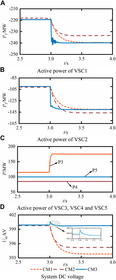
FIGURE 7. VSC3 power increase simulation.
As can be seen in Figures 7A–D, in the initial state, the actual power values of VSC1 and VSC2 under the three control methods are close to the power command value because of the existence of losses in the system, but there is a slight difference. After the change of the active power command value of VSC3 at the moment of 3 s, it is equivalent to the power surplus of the DC system, and the DC voltage of the system is gradually reduced. Under the control of CM1, the droop stations VSC1 and VSC2 adjust their active power command values according to the amount of change in DC voltage by a fixed droop coefficient, and the transmitted power changes from −219.5 MW and −100 MW to −239.5 MW and −140 MW, respectively, with a sharing amount of 20 MW and 40 MW, and a DC voltage deviation of 6.08 kV.
Under CM2 control, the droop coefficient is obtained by calculating according to the fixed margin of the converter station, which optimizes the power distribution of the DC system compared to CM1 control, thus reducing the deviation of the DC voltage. The sharing of VSC1 and VSC2 is 15.2 MW and 44.8 MW, respectively, and the deviation of the DC voltage is 4.57 kV.
Under the control of CM3, it can be seen from Figure 7D that the DC voltage first rises and then decreases, which is in line with the analysis in Section 3.1 of this paper. By feedforward compensation of unbalanced power to the active power command value of VSC1 and VSC2, the sharing of VSC1 and VSC2 are 20 MW and 40 MW, respectively, and the DC voltage deviation is 0.12 kV. Compared with CM1, the active power sharing of VSC1 and VSC2 does not change, while the DC voltage deviation is approximately zero, and quasi non-error DC voltage regulation is realized. The simulation results are shown in Table 2.
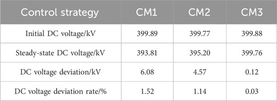
TABLE 2. Simulation results.
4.2 Validation of the effectiveness of the power balance allocation scheme
To verify the effectiveness of the power balance allocation scheme proposed in Section 3.2 of this paper, the comparison simulation set up in this section is as follows
Control Method 1 (CM1): Improved droop control; Control Method 2 (CM2): Improved droop control + power balance allocation scheme.
At t = 3 s, the VSC3 active power instruction value has increased from 115 MW to 175 MW. Figure 8 illustrates the comparison between simulation outcomes obtained with the two control methods.
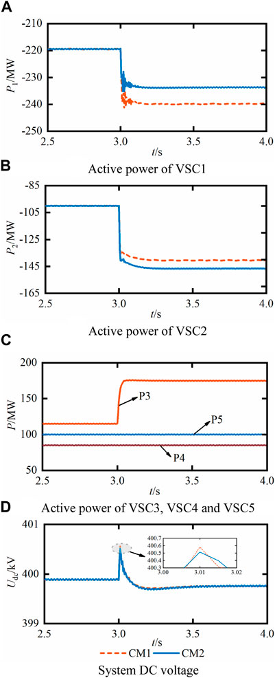
FIGURE 8. VSC3 power increase simulation.
As can be seen from Figures 8A–D, under CM1 control, the system’s unbalanced power is allocated to VSC1 and VSC2 through a fixed ratio without considering the actual power margin of the converter stations, which may easily cause some converter stations to be fully loaded and thus lose the ability to control the DC voltage when the unbalanced power is too large. The unbalanced power allocated to VSC1 and VSC2 is 20 MW and 40 MW, respectively, and the DC voltage deviation is 0.12 kV.
Under CM2 control, the system’s unbalanced power is reasonably allocated to VSC1 and VSC2 according to the power margin of the converter station, which avoids the problem that VSC1, which has a small power margin, can easily reach full load. The unbalanced power allocated to VSC1 and VSC2 are 14 MW and 46 MW, respectively, and the deviation of the DC voltage is 0.12 kV the simulation results are shown in Table 3.
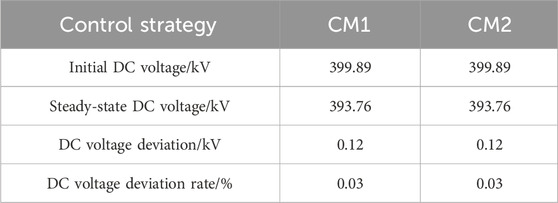
TABLE 3. Simulation results.
4.3 Validation of the effectiveness of secondary regulation control of DC voltage
To verify the effectiveness of the DC voltage secondary regulation control strategy proposed in Section 3.3 of this paper, the comparative simulations set up in this section are as follows:
At t = 3 s, the active power command value for VSC3 is reduced from 115 MW to 45 MW. Figure 9 presents a comparison of the simulation outcomes across the three control methods.
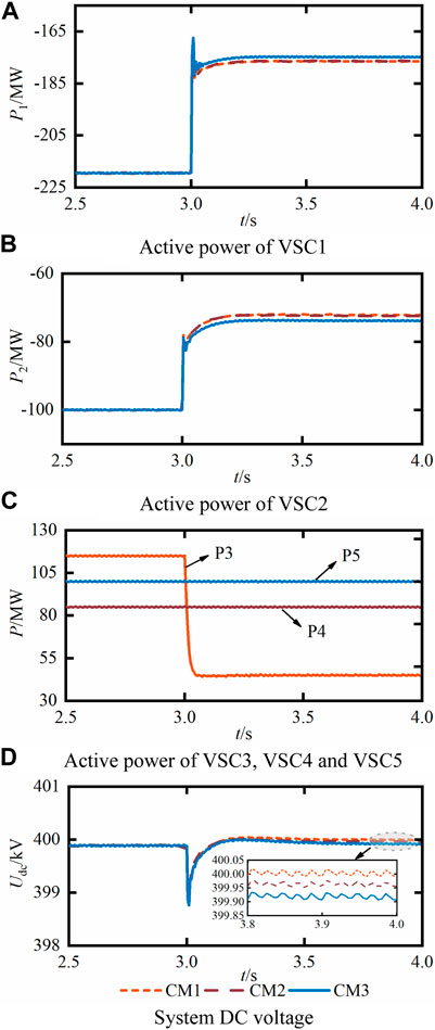
FIGURE 9. VSC3 power reduction simulation.
From Figures 9A–D, it can be seen that when the system has a power deficit, the DC voltage first decreases and then increases, which is consistent with the analysis in Section 3.1 of this paper. Under CM1 control, since the system does not have a DC voltage recovery controller, the DC voltage stabilization value still deviates from the initial value, with a deviation value of 0.11 kV. Under CM2 control, it can be seen from Figure 9D that the additional DC voltage stabilizer can further reduce the DC voltage deviation, with a deviation value of 0.08 kV. Since the ΔKu and ΔKv parameters are fixed values, which limits the DC voltage recovery effect, the DC voltage is gradually recovered under CM3 control by adjusting the active power reference values of VSC1 and VSC2 in small increments using the static-free characteristic of the PI controller. When the system reaches the steady state again, the DC voltage deviation is 0.02 kV. Simulation results are shown in Table 4.
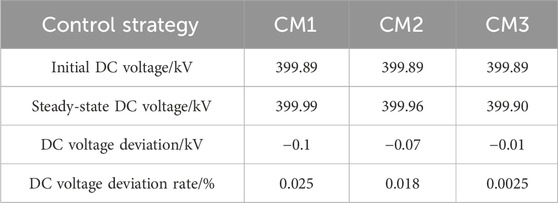
TABLE 4. Simulation results.
5 Conclusion
In this paper, we propose an enhanced coordinated control approach for VSC-MTDC systems, which includes secondary regulation of DC voltage. The aim is to address the inherent DC voltage deviation issue that arises from conventional droop control in the presence of unbalanced power dissipation at converter stations. Our findings suggest that this approach provides superior outcomes.
(1) The quasi non-error DC voltage regulation can be realized by compensating the active power reference value of the converter station through the feed-forward and shifting the droop curve.
(2) The unbalanced power is allocated according to the power margin of converter stations, which can effectively avoid the situation that some converter stations are overloaded while other converter stations still have a power margin.
(3) The DC voltage deviation can be further reduced by the DC voltage secondary regulation controller to improve the stability of system operation.
Data availability statement
The raw data supporting the conclusions of this article will be made available by the authors, without undue reservation.
Author contributions
CL: Writing–original draft. XZ: Writing–original draft. PH: Writing–original draft. KZ: Writing–review and editing. LL: Writing–review and editing.
Funding
The author(s) declare financial support was received for the research, authorship, and/or publication of this article. This work is jointly supported by the Key Programs of Higher Education Institutions in Henan Province (No. 23A470011), and National Natural Science Foundation of China project (No. 52377125), and the Smart Grid Sichuan Key Laboratory 2022 Open Fund Project (No. 2022-IEPGKLSP-KFYB01).
Conflict of interest
Author LL was employed by Henan Xuji Instrument Co. Ltd.
The remaining authors declare that the research was conducted in the absence of any commercial or financial relationships that could be construed as a potential conflict of interest.
Publisher’s note
All claims expressed in this article are solely those of the authors and do not necessarily represent those of their affiliated organizations, or those of the publisher, the editors and the reviewers. Any product that may be evaluated in this article, or claim that may be made by its manufacturer, is not guaranteed or endorsed by the publisher.
References
Fu, Q., Du, W. J., Wang, H. F., Ren, B. X., and Xiao, X. Y. (2021b). Small-signal stability analysis of a VSC-MTDC system for investigating DC voltage oscillation. IEEE Trans. Power Syst. 36 (6), 5081–5091. doi:10.1109/TPWRS.2021.3072399
Fu, Y., Shao, X. Y., and Li, H. (2021a). Transient voltage stability control strategy of DC distribution network. High. Volt. Eng. 47 (4), 1354–1362. doi:10.13336/j.1003-6520.hve.20200040
He, P., Zhang, X. W., Li, C. S., Yun, L., Yang, H., and Yan, Y. B. (2023). Smooth regulation of DC voltage in VSC-MTDC systems based on optimal adaptive droop control. Tech. Gaz. 30 (4), 1234–1240. doi:10.17559/TV-20220806130349
Li, H., Meng, K., Li, X., and Peng, Y. F. (2022). Simulation of wind power integration with modular multilevel converter-based high voltage direct current. Tech. Gaz. 29 (1), 301–307. doi:10.17559/TV-20210729043234
Li, Y. H., and Gao, L. (2020). Control strategy of flexible DC distribution system based on droop characteristics. Mod. Electr. Power 37 (4), 391–399. doi:10.19725/j.cnki.1007-2322.2019.0574
Li, Z., Li, Y. Z., Lu, Y. P., Zhan, R. P., He, Y., and Zhang, X. P. (2019b). Active power balance oriented coordinating control strategy for VSC-MTDC system. Automation Electr. Power Syst. 43 (17), 117–124. doi:10.7500/AEPS20181224003
Li, Z., Li, Y. Z., Zhan, R. P., He, Y., and Zhang, X. P. (2019a). AC grids characteristics oriented multi-point voltage coordinated control strategy for VSC-MTDC. IEEE Access 7, 7728–7736. doi:10.1109/ACCESS.2018.2890406
Liu, C. R., Liu, H. Y., Jiang, S. W., and Zheng, L. (2023). Dynamic frequency support and DC voltage regulation approach for VSC-MTDC systems. CSEE J. Power Energy Syst. 9 (2), 645–658. doi:10.17775/CSEEJPES.2021.01790
Liu, H. Y., Liu, C. R., Zheng, L., and Wang, Q. Q. (2022b). Cooperative optimal droop control for VSC-MTDC system with quasi non-error DC voltage regulation. Automation Electr. Power Syst. 46 (6), 117–126. doi:10.7500/AEPS20210706007
Liu, Q., Wang, Y. Z., Wang, S. X., Liang, D., Zhao, Q. Y., and Zhao, X. S. (2022a). Voltage regulation strategy for DC distribution networks based on coordination of centralized control and adaptive droop control. IEEE Trans. Power Deliv. 37 (5), 3730–3739. doi:10.1109/TPWRD.2021.3135884
Liu, Y. P., Xie, S., Liang, H. P., and Xie, Q. (2020). Adaptive droop control strategy for VSC-MTDC system considering DC voltage errors among converter stations. Trans. China Electrotech. Soc. 35 (15), 3270–3280. doi:10.19595/j.cnki.1000-6753.tces.190722
Ma, W. Z., Guang, Z. J., Zhang, K. T., Zhang, J., Yao, Y. X., and Li, M. S. (2022). Live test technology for metal shielding of medium and low voltage power cables in continuous state. Electr. Power Eng. Technol. 41 (06), 75–81+139. doi:10.12158/j2096-3203202206.009
Song, S. G., Roy, M., and Gilsoo, J. (2021). Cost-based adaptive droop control strategy for VSC-MTDC system. IEEE Trans. Power Syst. 36 (1), 659–669. doi:10.1109/TPWRS.2020.3003589
Wang, W. Y., Yin, X., Cao, Y. J., Jiang, L., and Li, Y. (2021). A distributed cooperative control based on consensus protocol for VSC-MTDC systems. IEEE Trans. Power Syst. 36 (4), 2877–2890. doi:10.1109/TPWRS.2021.3051770
Wang, Y. Z., Qiu, F. L., Liu, G. W., Lei, M., Yang, C., and Wang, C. S. (2023). Adaptive reference power based voltage droop control for VSC-MTDC systems. J. Mod. Power Syst. Clean Energy 11 (1), 381–388. doi:10.35833/MPCE.2021.000307
Wang, Z. J., He, J. H., Xu, Y., and Zhang, F. (2020). Distributed control of VSC-MTDC systems considering tradeoff between voltage regulation and power sharing. IEEE Trans. Power Syst. 35 (3), 1812–1821. doi:10.1109/TPWRS.2019.2953044
Xiong, Y. X., Yao, W., Shi, Z. T., Fang, J. K., Ai, X. M., Wen, J. Y., et al. (2022). Adaptive dual droop control of MTDC integrated offshore wind farms for fast frequency support. IEEE Trans. Power Syst. 38 (3), 2525–2538. doi:10.1109/TPWRS.2022.3179504
Yang, L., Zhao, J. J., Liu, H., Kong, Q. K., Zhao, Y. H., Cheng, L., et al. (2022). Adaptive droop control of the VSC-MTDC distribution network considering power–voltage deviation. Front. Energy Res. 9. doi:10.3389/fenrg.2021.814489
Yu, X., Lu, J., Dong, Y. L., Zhang, Q. W., Gan, Z. Y., and Wang, Y. Z. (2022). A steady-state voltage control method for a multi-terminal hybrid UHVDC transmission system. Power Syst. Prot. Control 50 (1), 174–180. doi:10.19783/j.cnki.pspc.210206
Keywords: droop control, VSC-MTDC, DC voltage deviation, power margin, secondary regulation
Citation: Li C, Zhang X, He P, Zhao K and Liu L (2024) Improved coordinated control strategy for VSC-MTDC system with DC voltage secondary regulation. Front. Energy Res. 12:1363267. doi: 10.3389/fenrg.2024.1363267
Received: 30 December 2023; Accepted: 05 February 2024;
Published: 21 February 2024.
Edited by:
Liansong Xiong, Xi’an Jiaotong University, ChinaReviewed by:
Fei Jiang, Changsha University of Science and Technology, ChinaXiaokang Liu, Polytechnic University of Milan, Italy
Copyright © 2024 Li, Zhang, He, Zhao and Liu. This is an open-access article distributed under the terms of the Creative Commons Attribution License (CC BY). The use, distribution or reproduction in other forums is permitted, provided the original author(s) and the copyright owner(s) are credited and that the original publication in this journal is cited, in accordance with accepted academic practice. No use, distribution or reproduction is permitted which does not comply with these terms.
*Correspondence: Congshan Li, NTQzNjI3NzY3QHFxLmNvbQ==