 Mohamed S. Amin1
 Mahmoud A. Attia1
 Amr K. Khamees2
 S. F. Mekhamer3
 Hossam Kotb4
 Kareem M. AboRas4*
 Amr Yousef5,6*
- 1Department of Electrical Power and Machines, Faculty of Engineering, Ain Shams University, Cairo, Egypt
- 2Department of Engineering Physics and Mathematics, Faculty of Engineering, Ain Shams University, Cairo, Egypt
- 3Electrical Engineering Department at Future University, New Cairo, Egypt
- 4Department of Electrical Power and Machines, Faculty of Engineering, Alexandria University, Alexandria, Egypt
- 5Electrical Engineering Department, University of Business and Technology, Jeddah, Saudi Arabia
- 6Engineering Mathematics and Physics Department, Faculty of Engineering, Alexandria University, Alexandria, Egypt
This paper attempts to obtain the optimal solution to enhance the performance of the Automatic Voltage Regulator (AVR) Controller, as it is an essential tool to control the synchronous generator output voltage. The controller improves AVR system stability and response time; moreover, it is demonstrated that the Proportional Integral Derivative (PID) controller achieves the goal by applying two artificial intelligence techniques to design the optimal values of the Automatic Voltage Regulator (AVR) PID controller for a single area model. The first is the Exponential Distribution Optimization Algorithm (EDO), and the second is the Transit Search Optimization Algorithm (TS). EDO and TS are used to determine the best PID controller parameters and have also recently been developed in the breadth of optimization problems and associated computational complexities field. The objective function, Integrated Square Error (ISE), minimizes the error voltage for improved stability and response. The outcomes are compared to various optimization techniques to prove the validation of the two proposed methods. The results show that the EDO and TS proved their superiority through their stability level to the AVR system and their steady-state error improvement. Moreover, the dominant effect of damping frequency decreases the oscillation and the reduced maximum overshoot that protects the loads from being subjected to non-permissible over-voltage levels. Finally, a robustness test is applied to the two proposed optimization methods to prove their reliability and effectiveness.
1 Introduction
In this section, the background of the AVR system is presented. Moreover, a literature review showing the research gap, motivation, and suitable controller is presented at the end of the section.
1.1 Background
The function of AVR is to maintain the terminal voltage magnitude of a synchronous generator at a certain level. Figure 1 represents a simplified AVR schematic diagram. The terminal voltage magnitude decreases as the generator’s reactive power load increases. The magnitude of the voltage is measured using a potential transformer in one phase. This voltage is rectified and compared to a reference voltage. The amplified error signal controls the exciter field and increases the voltage at the exciter terminals. As a result, the generator field current increases, which raises the generated emf. The reactive power generation is boosted to a new equilibrium, resulting in the required terminal voltage (Ula and Hasan, 1992). We will quickly examine the simplified AVR system components (Saadat, 1999).
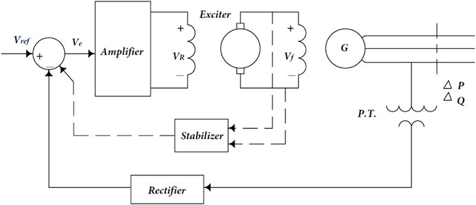
FIGURE 1. A typical arrangement of a simple AVR.
1.2 Literature review
The following researchers improved the AVR control system in 2013 (Bendjeghaba, 2014) by using the particle swarm optimization (PSO) algorithm to optimize the controller parameters (PID) and produce high-quality solutions. In 2014 (Bendjeghaba, 2014), a tuning strategy based on the Continuous Firefly algorithm (CFA) was used to determine the controller parameters (PID), reach the optimal solution, and compare them with the PSO algorithm to obtain the best.
In 2015 (Yavarian et al., 2015), an Adaptive Neuro-Fuzzy Inference System (ANFIS) was used to improve the performance of the AVR system under tunning the controller parameters by using a combination of Signal-to-Noise Ratio (SNR) and Particle Swarm Optimization (PSO) algorithms and comparing the results with the Genetic Algorithm (GA). In 2016 (babu and Chiranjeevi, 2016), a method was developed to calculate the FOPID controller parameters using the Genetic Algorithm (GA) and Ant Colony Optimization (ACO) approaches. In 2017 (Sambariya and Gupta, 2017), the Monarch Butterfly Optimization Algorithm (MBO) based on migratory behavior was provided to discover the optimal values of the AVR system’s PID parameters. In 2018 (Blondin et al., 2018), the authors used the Cuckoo Search (CS) algorithm to tune controller parameters with a new time domain criterion to improve dynamic performance and compare with other optimization techniques. In 2018 (Çelik and Durgut, 2018), applying the symbiotic organisms search (SOS) algorithm to solve the problem of efficient design of PID controller was applied to popular automatic voltage regulator (AVR) system. In 2018 (Çelik and Öztürk, 2018), incorporating a hybrid symbiotic organisms search and simulated annealing (hSOS-SA) technique into the efficient design of the PID controller for the automatic voltage regulator (AVR). In 2019 (Ekinci and Hekimoğlu, 2019), an improved kidney-inspired algorithm (IKA) was utilized to enhance the stability and AVR system performance. In 2020 (Oladipo et al., 2020), a simple overview of PID and FOPID controller optimization using next-generation metaheuristic algorithms for managing the AVR system was presented. In 2021 (Ibrahim et al., 2021), the Jaya & Rider optimization algorithm achieved high stability and was best for both rising and settling times, which enhanced the system’s performance. In 2021 (Eke et al., 2021), the heuristic optimization-based 2DOF state feedback PI-controller, which controls voltage output significantly in the presence of severe and continuous disturbances by using the amplifier output signal as additional feedback into the controller. In 2022 (Habib et al., 2022), the developed IWO-AVR system withstood parameter changes, ensuring reliable operation during such changes. In 2022 (Kumar et al., 2022), the proposed MPC-HHO controller was verified its effectiveness in controlling combined voltage and frequency regulation for an interconnected multi-source multi-area power system with two areas. Recently, in 2023 (Ekinci et al., 2023a), the mOBL-INFO techniques developed were used to tune a real PIDD2 controller for the AVR system and to achieve superior transient response performance for AVR system control. In (Ekinci et al., 2023b), the developed enAO method is presented to create a PID plus second-order derivative (PIDD2) controller for application in an AVR system to improve efficiency and dynamic system stability. In (Izci et al., 2023), as a result, this study first discusses various controller types that demonstrate distinct capabilities based on their tuning strategies and then introduces an intelligent optimization approach using a fractional-order proportional integral derivative with double derivative (FOPIDD2) controller tailored for AVRs that exhibits the best stability, confirming its effectiveness. In (Gandhi et al., 2023), MESOBC guaranteed robust performance for the AVR of the power system under diverse operating conditions.
1.3 An appropriate controller
The PID controller is the most commonly utilized feedback controller in industry. It has been used successfully by industry houses for over 50 years. It is a simple and robust controller that can provide outstanding control performance despite the process plant’s different dynamic characteristics (Çelik and Durgut, 2018).
1.4 Proper optimization techniques
Based on the optimization techniques mentioned above and seeking further improvement of the response of the AVR system, in this paper, the Transit Search Optimization Algorithm (TS) published in 2022, as the results showed that it has the lowest overall average error for the benchmark problems when compared to the other efficient techniques and the total average error for the 73 problems described in this study was determined for the 14 algorithms, and it was discovered that the proposed TS method performed best with the lowest average error compared to the other optimization techniques (Mirrashid and Naderpour, 2022), and the Exponential Distribution Optimization Algorithm (EDO) published in 2023 that has a high explorative capability due to the usage of two winners determined at random among winners to develop two other individuals who share various characteristics with these winners in order to uncover potential areas of the search space and it is distinguished by its ease of implementation and its explorative and exploitative capabilities. Statistical research suggests that the proposed EDO is superior at a 95% confidence level (Abdel-Basset et al., 2023).
EDO and TS are used for better results as powerful tools for solving optimization algorithm problems and the most advanced optimization algorithm methods, showing their efficiency in stabilizing steady state error values under different disturbances in the AVR system, so they are utilized to find the optimal PID controller parameters, while the objective function to improve stability and response, Integrated Square Error (ISE), is employed to minimize error voltage (Khan et al., 2019). The results are compared with several optimization strategies to identify the best performance and stability of the AVR system.
1.5 Motivation and originality
- Enhancement of the dynamic performance of the AVR system under fixed and variable references.
- Minimizing the error in voltage for improved stability and response through the ISE objective.
- Using relatively new optimization techniques in the application of tuning the PID controller parameters.
- The analysis is done in the time and frequency domains.
- Proving the reliability and effectiveness of the proposed optimization techniques via comparative studies with others and robustness tests.
2 AVR system model
The four essential components of an AVR system model are the amplifier, exciter, generator, and sensor. As illustrated in Figure 2, these components neglect saturation and nonlinearity.
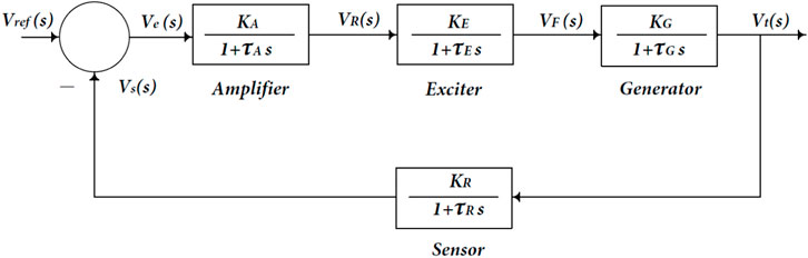
FIGURE 2. A simplified automatic voltage regulator block diagram.
2.1 Amplifier model
The amplifier is expressed by a gain KA [10:400] and a time constant τA [0.02:0.1s], and the transfer function is given using Eq. 1:
2.2 Exciter model
A linearized model is an acceptable model of a modern exciter that ignores saturation or other nonlinearities. The transfer function can be expressed using Eq. 2 by a minimal time constant τE and a gain KE.
2.3 Generator model
In the simplest model, the generator’s terminal voltage is related to its field voltage. The transfer function can be expressed using Eq. 3 by a gain KG [0.7:1] and a time constant τG [1.0:2.0s], but in fact, the generated emf of the synchronous machine is a function of the machine magnetization curve. Its terminal voltage depends on the generator load.
2.4 Sensor model
The voltage is measured using a potential transformer and rectified via a bridge rectifier in one form or another. The sensor is expressed by a gain KR and a time constant τR [0.01:0.06s], and the transfer function is given using Eq. 4:
The open-loop transfer function of the block diagram in Figure 2 is given using Eq. 5:
and the closed-loop transfer function relating the generator terminal voltage Vt (s) to the reference voltage Vref (s) is given using Eq. 6:
3 Controller
The proportional integral derivative (PID) controller is one of the most prevalent commercially available controllers. The proportional integral derivative (PID) controller is the most preferred of the offered controllers. The PID controller differs from other types of controllers due to its robust performance over a wide variety of operating situations and simplicity of structure design. The PID controller has three control parameters: proportional, integral, and derivative gains. Various heuristic optimization strategies have been developed to improve the voltage response of the AVR system. These methodologies have gained acceptance among researchers across the world (Chatterjee et al., 2016). The PID controller is the most commonly utilized feedback controller in industry. It has been used successfully by industry houses for over 50 years. It is a simple and robust controller that can provide outstanding control performance despite the process plant’s different dynamic characteristics (Çelik and Durgut, 2018). The PID controller is used to increase the dynamic response while also decreasing or eliminating the steady-state error. The derivative controller increases the transient response by adding a finite zero to the open-loop plant transfer function. The integral controller introduces a pole at the origin, increases the system type by one, and decreases the steady-state error caused by a step function to zero (Kiam Heong et al., 2005). The transfer function of the PID controller is given using Eq. 7:
The block diagram of an AVR compensated with a PID controller is shown in Figure 3.
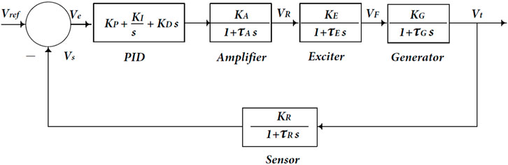
FIGURE 3. AVR system with PID controller.
4 Optimization techniques
Optimization techniques tune the controller parameters using artificial intelligence or evolutionary computation. The optimization techniques employed are EDO and TS through the AVR system.
4.1 Exponential distribution optimizer (EDO)
Exponential Distribution Optimization Algorithm (EDO) has a high explorative capability due to the use of two winners determined at random among winners to develop two other individuals who share various characteristics with these winners to uncover potential areas of the search space, and it is distinguished by its ease of implementation and its explorative and exploitative capabilities. Statistical research suggests that the proposed EDO is superior at a 95% confidence level (Abdel-Basset et al., 2023).
The exponential distribution is a continuous distribution that deals with the amount of time it takes for an event to occur. The following is the Probability Density Function (PDF) of the random variable χ and can be given using Eq. 8:
4.1.1 The memoryless property
A random variable x has a memoryless property, so the previous history of the solutions is neglected.
Figure 4 depicts a visual idea of winner populations and memoryless solutions. The memoryless property can be described by Eqs 9–13.
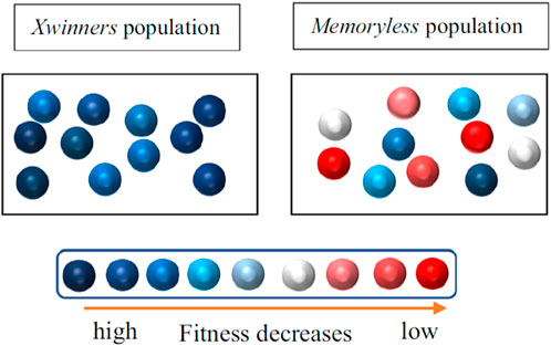
FIGURE 4. Depiction for the populations of winners and memoryless solutions.
4.1.2 Exploitation
The EDO exploitation phase depends on the following principles: memoryless property, standard variance, and mean to update the new solution. Figure 5 represents the EDO exploitation phase in the optimization model. The Exploitation can be described using Eq. 14.
a and b are variables that can be changed. ϕ is a random number in the range [0, 1]. f is an integer created randomly in the range [-1, 1].

FIGURE 5. Exploitation phase of EDO.
4.1.3 Exploration
The EDO exploration phase optimization model is developed using two random winners from the initial population who follow the exponential distribution (Xwinners rand1, Xwinners rand2) and updated using Eqs 15–20 as follows:
N: The population size.
d: The dimension of the problem
max_time: The total number of iterations.
Mtime: The average of all solutions acquired in the initial population.
c: is an adjusted parameter representing the information exchange ratio between the Z1 and Z2 vectors.
4.1.4 EDO optimizer
The Flowchart of EDO is shown in Figure 6.
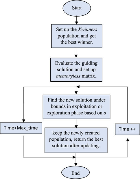
FIGURE 6. The flowchart of the EDO Optimizer.
To solve our problem, select the values of the EDO parameters as following:
Switch parameter (α) = 0.5
Population type (N) = 30.
4.2 Transit search algorithm technique
One of the most essential goals of exoplanet exploration is to find viable worlds. A planet must have certain parameters to be a good host for life. The results showed that it has the lowest overall average error for the benchmark problems when compared to the other efficient techniques, and when the total average error for the 73 problems described in this study was determined for the 14 algorithms, it was discovered that the proposed TS method performed best with the lowest average error compared to the other optimization techniques (Mirrashid and Naderpour, 2022). The TS implementation is divided into five phases (see Figure 7): galaxy, transit, planet, neighbor, and exploitation. Details on each of these phases are provided in this section (Haswell, 2010).
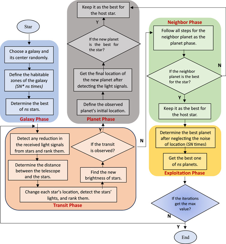
FIGURE 7. Flowchart of TS algorithm.
4.2.1 Galaxy phase
Getting the best location for stellar systems Ls (regions with a high likelihood of hosting life) (Winther, 2020) is shown in Figure 8 by using several iterations applied to the fitness of each star located at LS,i,j using Eqs 21–26 as follows:
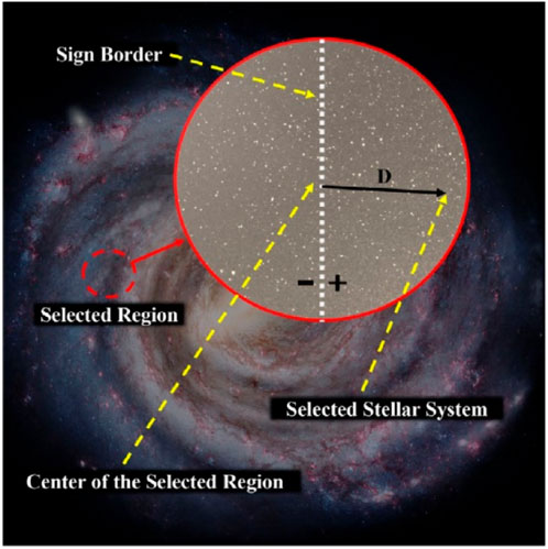
FIGURE 8. The selection process of the stellar systems by TS.
ns: No. of host stars. and SN: Signal-to-noise ratio.
LR,l: The fitness of the stellar system is located.
LR: The initial locations for the best regions of the stellar systems.
LGalaxy: The random location for the center region of the galaxy.
4.2.2 Transit phase
The light the star receives must be re-measured to detect any reduction in the received light signals and identify the transit. This pahse can be represented using Eqs 27–33 as follows:
Li: The luminosity and Ri, the rank of the star i are represented.
di: The distance between the telescope and the star i.
Lt: The telescope’s position (random).
If PT is greater than one, the planet phase is utilized; otherwise, the neighbor phase is used in the current iteration.
4.2.3 Planet phase
Transit happens when the planet passes between the star and the telescope (Figure 9). This pahse can be represented using Eqs 34–37 as follows:
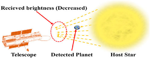
FIGURE 9. The space telescope captured the transit (the detected planet is located between the telescope and the star).
Lz: The identified planet’s initial location.
To consider the planet’s orbital position in the TS algorithm, three zones are considered and affected by applying the zone parameter (z) in the planet phase (see Eq. 36; Figure 10) (Hahn et al., 2019).
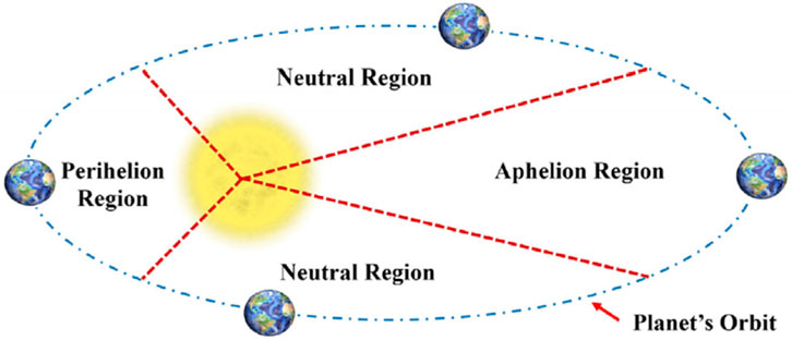
FIGURE 10. A planet’s orbit around a star and the corresponding zones in the algorithm.
4.2.4 Neighbore phase
If no transit (PT = 0) is detected for a star in the current observation, the neighborhood planets of the previously detected planet for the star will be investigated.
4.2.5 Exploitation phase
In this phase, the best LE can find the best planet for each star using Eqs 38–41.
C15 (a random no.) = [0,2]; C16 (a random no.) = [0,1]; K =(C17)P Lr, C17 (a random vector) = [0,1]; P (a random power) = [1…., SN].
LE: refers to the planet’s characteristics.
Note That: To solve our problem, select the values of the TS parameters as following:
Number of host stars (ns) = 2.
Signal-to-noise ratio (SN) = 5.
5 Objective function
The objective function aims to reduce the error voltage (ΔVe), which is the difference between the reference voltage and the terminal voltage feedback (sensor voltage). The objective function denotes improved stability and faster reaction. Many performance criteria are applied to achieve the best solution, including Integrated Square Error (ISE) (Soundarrajan et al., 2010). ISE will be used in this paper using Eq. 42 due to its time independence, which makes it deal with all errors with equal weight. Also, it is simpler than the time-independent functions, such as integrated time-weighted squared error.
The optimization technique starts with its initial state to tune the controller parameters (random numbers are initially chosen inside the boundaries). The goal function minimizes the error voltage, and the controller parameters are changed using the optimization procedure sequence until the optimum solution of the controller parameter or the maximum iteration is attained. The controller parameter values influence the AVR system’s response and stability. The AVR system model with objective function and controller is shown in Figure 11.
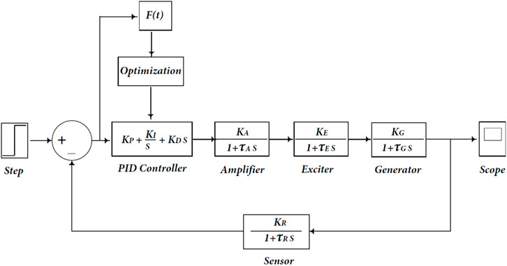
FIGURE 11. AVR system model with objective function and controller tuning optimization.
6 Simulation results
Using MATLAB R2021a, 64-bit/SIMULINK runs on a machine with an Intel Core i5 eighth Gen. processor running at 1.8 GHz and 8 GB of RAM. The AVR system mentioned above has been implemented. The AVR system’s main component parameters are KA = 10, KE = 1, KG = 1, KS = 1, TA = 0.1, TE = 0.4, TG = 1, and TS = 0.01 (Gaing, 2004). The AVR system model with specific component parameters is presented in Figure 12.
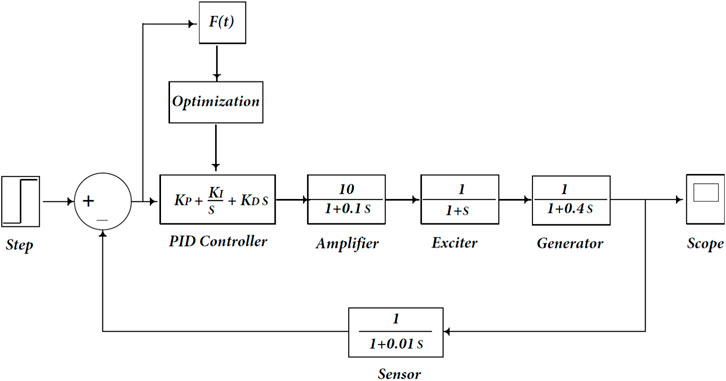
FIGURE 12. The AVR system model with specific component parameters.
The following case studies are performed on an AVR system model using MATLAB/SIMULINK:
AVR system model based on the PID controller with EDO and TS. Each case study produces a transient response (output voltage), eigenvalues, root locus, and Bode diagram. Two case studies are compared with SSA, SFS, GOA, and TLBO and are submitted in (Mosaad et al., 2018) to determine which system provides the best reaction and stability. The maximum number of iterations in these optimization strategies is set to 100. The EDO and TS populations are set to 100 in all calculations, and ISE is used as an objective function.
6.1 AVR system model using PID controller
The PID controller comprises three design variables (Kp, Ki and Kd) with values ranging from 0 to 1. EDO and TS are optimization techniques used to tune the PID controller. They are compared to others to evaluate how they affect the performance and reaction of the AVR system model. EDO and TS transfer functions are depicted in the following Eqs 44–46: (Saadat, 1999; Ekinci et al., 2018)
Transfer function in case of using EDO algorithm technique:
Transfer function in case of using TS algorithm technique:
6.1.1 Transient response
The AVR model in Figure 12 is utilized, with a step voltage of one P.U. The terminal voltage response of the AVR system for the two optimization techniques (EDO and TS) is shown in Figure 13. The performance of various optimization techniques is shown in Table 1. This table illustrates that the behavior of the AVR system utilizing EDO and TS optimization strategies is nearly identical and better than other methods, such as damping frequency having a more decisive influence than others, the number of oscillation cycles being reduced, and the steady-state error being reached faster and more stabilized. EDO and TS have higher performance and reaction (lower maximum overshoot and settling time) than other approaches, such as SFS, GOA, and TLBO. Since the maximum overshoot values in the proposed EDO and TS optimization techniques reach 89.6% of SFS, and 90% of TLBO, and 91.2% of GOA, the system response is faster than the other methods (see Figure 13), more stable, and has fewer oscillation cycles than the other approaches.
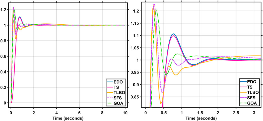
FIGURE 13. Terminal voltage of AVR system using EDO&TS-PID controller Vs. other optimization techniques.
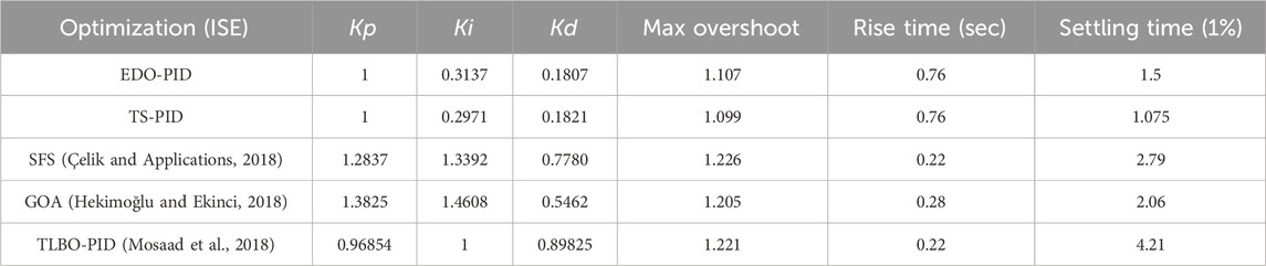
TABLE 1. Optimization techniques response using PID controller.
6.1.2 Root locus and eigenvalues
The root locus diagrams of EDO and TS on an AVR system with a PID controller are shown in Figures 14, 15, compared to the root locus diagrams of GOA shown in Figure 16. The EDO, TS, and root locus diagrams are derived from Equations 45, 46. Table 2 shows how the poles (eigenvalues) and damping ratio are retrieved from the root locus diagram for each optimization technique. This table also displays the poles and damping ratios for several optimization strategies, such as TS, EDO, SFS, and GOA, with a PID controller. According to this table, TS and EDO have a higher damping ratio than other optimization techniques. Moreover, the root locus indicates that all three controllers are stable, as all the roots are on the negative side of the S-plane.
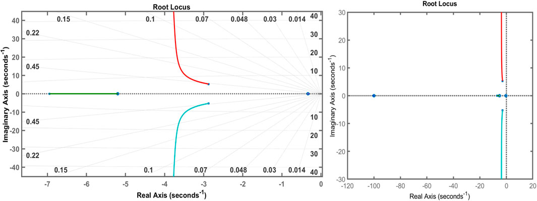
FIGURE 14. Root locus of EDO-PID controller.
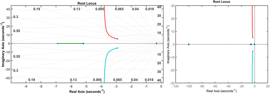
FIGURE 15. Root locus of TS-PID controller.
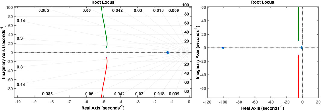
FIGURE 16. root Locus of GOA.
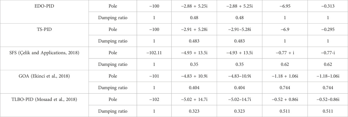
TABLE 2. Poles and damping ratio of optimization techniques using PID controller.
6.1.3 Bode diagram
The Bode diagrams of EDO and TS are shown in Figures 17–19, respectively. It shows that the closed-loop system is stable. Table 3 shows how the Bode diagram calculates the phase margin, gain margin, peak margin, delay margin, and bandwidth. TS and EDO have almost the same peak margin, phase margin, bandwidth, and delay margin. This means the same level of frequency stability. The peak margin with the EDO and TS optimization techniques is lower than TLBO, SFS, and GOA, respectively, with 53%–54%, 58%–59%, and 86%–88%, with an increase in the phase margin value of 43%–43.8% and 36.4%–37.2%, 15.9%–16.6% of TLBO, SFS, and GOA, respectively, as well as an increase of 2.3–4 times in the delay margin, which affects the system to have the highest frequency stability, and with the lowest bandwidth values of 37.4%–60.1% refers to the highest rise time as shown in Figure 13.
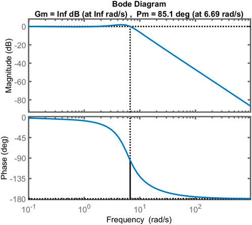
FIGURE 17. Bode Diagram of EDO-PID controller.
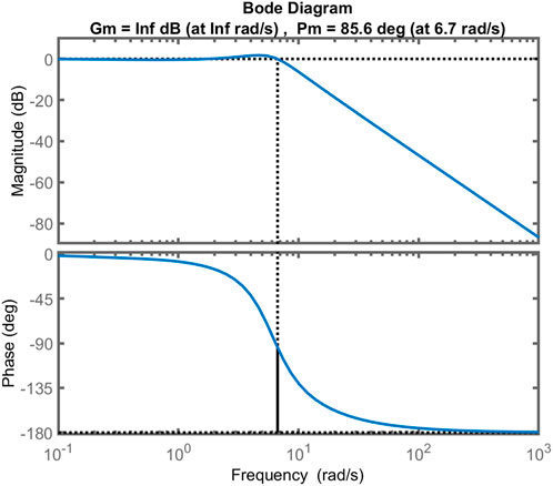
FIGURE 18. Bode Diagram of TS-PID controller.
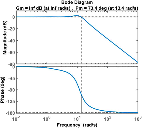
FIGURE 19. Bode Diagram of GOA-PID controller.
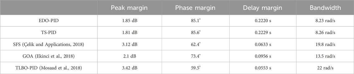
TABLE 3. Optimization techniques with PID controller poles and damping ratios.
It is clear that both EDO-PID and TS-PID have phase margins higher than the others, with a poorer improvement in TS than in EDO; thus, they are more stable. Also, the gain margin for both is infinite. Although both EDO and TS are more durable, they have a sluggish response with a delay of about 0.22 s for both and lower bandwidth. The following section applies a robustness test to EDO-PID and TS-PID to prove their reliability.
6.1.4 Convergence plots
To determine the convergence profile provided by TS and to check the algorithm’s robustness, the TS-based optimization algorithm is run 10 times under random initial conditions, and the results show the best particle versus iteration in Figure 20. This exercise proves the choice of 100 iterations is more than enough and demonstrates that the presented technique can search PID parameters for the considered power system with increased accuracy and a fast convergence rate.
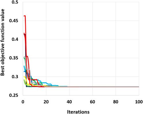
FIGURE 20. Best objective function value VS iteration numbers with 10 runs of TS.
6.2 Robustness analysis
Power system parameters and the operating point are subject to variation with changes in load. As a result, the parameters of the AVR system change as the load changes. The modified parameters are TA, TE, TG, and TS (time constants) (Mosaad et al., 2019). A PID controller tuned with TS is used in this analysis because it has the best response compared to the other mentioned techniques. The AVR time constants range from −50% to 50% of their nominal values. Figures 21–24 depict the terminal voltage of a synchronous generator with TA, TE, TG, and TS voltage change curves from −50% to 50%. The dynamic response specifications (maximum overshoot, rise time, settling time, and steady-state error) for the change in time constant parameters are shown in Tables 4, 5. These figures and tables demonstrate the AVR system’s robustness and TS-PID ability to provide good stability and response during load variation. It is noted that the value of steady-state error remains stable and constant as the time constant values change; additionally, the AVR system using the TS and EDO optimization techniques reaches the desired value of terminal voltage with an error of ±1% (settling time) due to these changes nearly at the same time. However, the max overshoot value changes with TS are lower than those of EDO. Robustness analysis demonstrates that the TS-PID output is sufficiently robust against loading change.
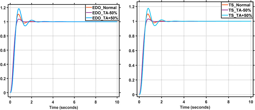
FIGURE 21. Voltage change curves from −50% to 50% of TA.
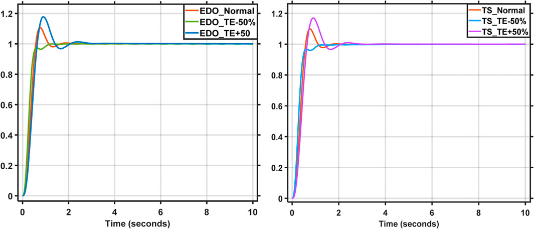
FIGURE 22. Voltage change curves from −50% to 50% of TE.
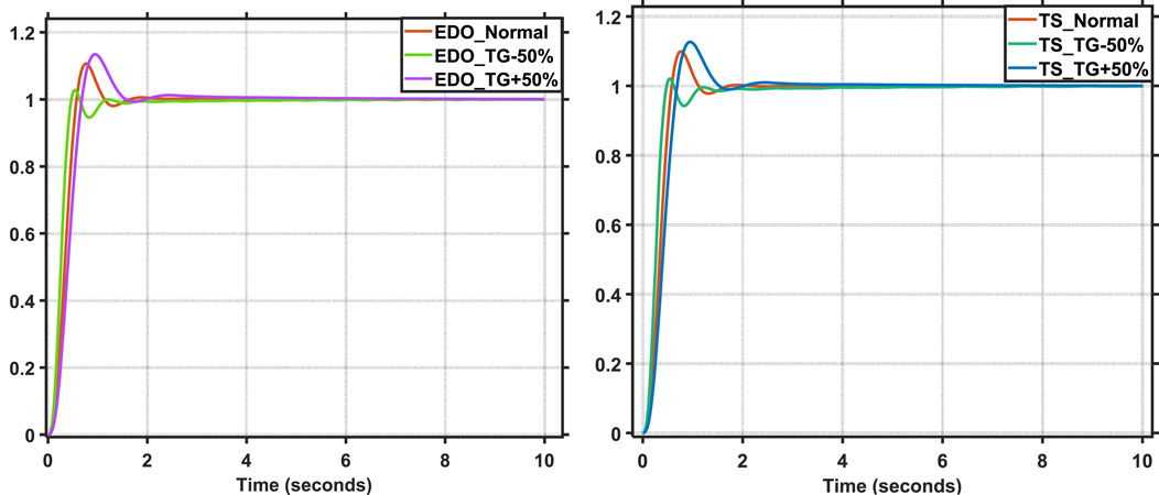
FIGURE 23. Voltage change curves from −50% to 50% of TG.
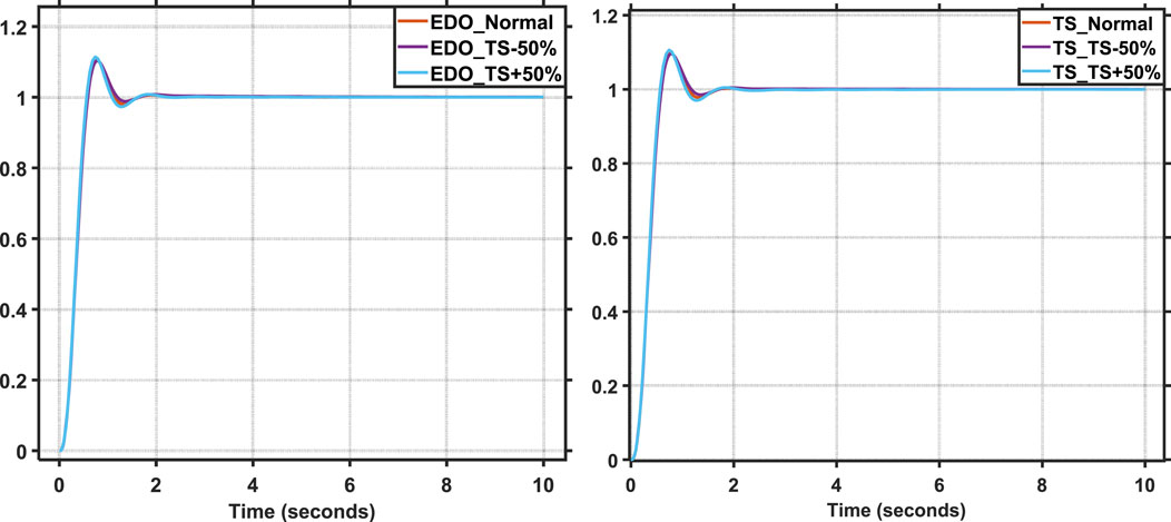
FIGURE 24. Voltage change curves from −50% to 50% of TS.
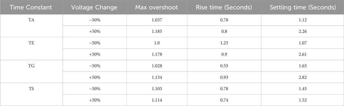
TABLE 4. EDO-PID dynamic response specification on variable time constants.
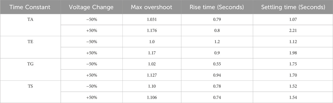
TABLE 5. TS-PID dynamic response specification on variable time constants.
Finally, the dynamic reference shown in Figure 25 is applied and a comparison is carried out again.

FIGURE 25. Dynamic Reference and AVR system response.
Figures 26–29 show the time response of the proposed methods against the SFS, GOA and TLBO based controller.

FIGURE 26. Dynamic voltage reference for simple AVR model.
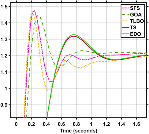
FIGURE 27. Focusing on the 1.2 pu step voltage reference case.
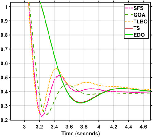
FIGURE 28. Focusing on the 0.4 pu step voltage reference case.
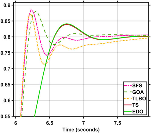
FIGURE 29. Focusing on the 0.8 pu step voltage reference case.
From Figures 26–29, with dynamic reference, the proposed controller with TS based has a lower overshoot and settling time than EDO-PID, SFS, GOA, and TLBO but a slightly slower response than them. Table 6 shows the voltage overshoot comparison between the proposed TS-PID controller and the other reported techniques for the simple AVR system at different step reference voltages.
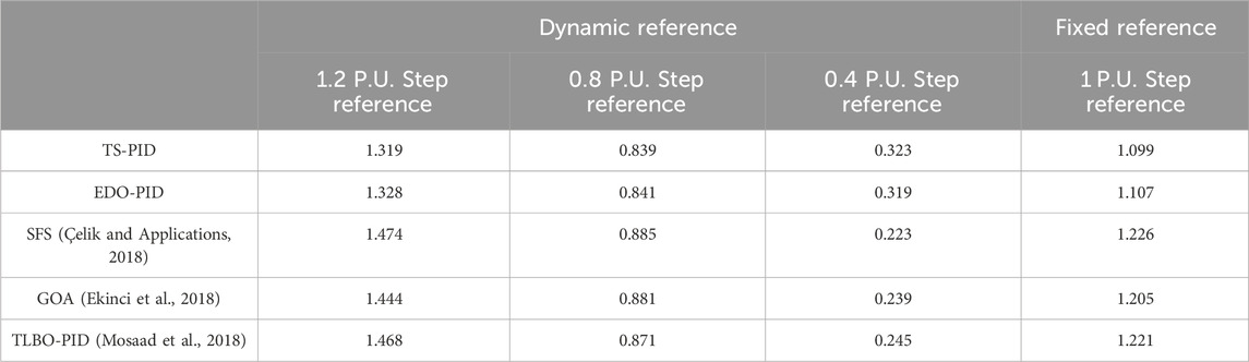
TABLE 6. The voltage overshoot for the proposed TS-PID controller compared with the other techniques.
From Table 6, the proposed method TS-PID follows the reference variations than the other methods.
7 Conclusion
The AVR system is used to control the synchronous generator terminal voltage. Without a controller, the AVR system model responds slowly, with a significant overshoot, a long settling period, and a substantial steady-state inaccuracy. TS and EDO demonstrate better responsiveness than the AVR system without a controller for the AVR system model that utilizes the PID controller. Using a PID controller, they also showed better stability in time and frequency responses than SFS, GOA, and TLBO. The EDO and TS employing a PID controller have lower overshoot settling times but higher rising times than other techniques. Moreover, they have a more excellent damping ratio, a higher phase margin, more considerable delay margin, and lower peak margin than the others. The same behavior of an AVR system utilizing EDO and TS optimization strategies and better than other methods, such as damping frequency has a dominant influence than others, a smaller number of oscillation cycles, and the steady-state error reaching a limited level. Finally, a robustness study is performed on TS and EDO to guarantee that load variation does not cause a significant deviation in the terminal voltage of the synchronous generator and that its response is acceptable within a reasonable time frame. The robustness analysis shows that the TS-PID output is adequately robust against changes in loading and setpoint tracking, and it is faster than EDO in terms of execution time (39.841 s << 434.574 s) for 100 iterations, with superior outcomes. For further research, apply the proposed optimization techniques to multi-area power systems to prove their efficiency and how they improve the dynamic response of AVR systems, and present a comparative study with other techniques.
Data availability statement
The original contributions presented in the study are included in the article/Supplementary material, further inquiries can be directed to the corresponding authors.
Author contributions
MoA: Conceptualization, Data curation, Formal Analysis, Funding acquisition, Investigation, Methodology, Project administration, Resources, Software, Supervision, Validation, Visualization, Writing–original draft, Writing–review and editing. MaA: Conceptualization, Data curation, Formal Analysis, Funding acquisition, Investigation, Methodology, Project administration, Resources, Software, Supervision, Validation, Visualization, Writing–original draft, Writing–review and editing. AK: Conceptualization, Data curation, Formal Analysis, Funding acquisition, Investigation, Methodology, Project administration, Resources, Software, Supervision, Validation, Visualization, Writing–original draft, Writing–review and editing. SM: Conceptualization, Data curation, Formal Analysis, Funding acquisition, Investigation, Methodology, Project administration, Resources, Software, Supervision, Validation, Visualization, Writing–original draft, Writing–review and editing. HK: Conceptualization, Data curation, Formal Analysis, Funding acquisition, Investigation, Methodology, Project administration, Resources, Software, Supervision, Validation, Visualization, Writing–original draft, Writing–review and editing. KA: Conceptualization, Data curation, Formal Analysis, Funding acquisition, Investigation, Methodology, Project administration, Resources, Software, Supervision, Validation, Visualization, Writing–original draft, Writing–review and editing. AY: Conceptualization, Data curation, Formal Analysis, Funding acquisition, Investigation, Methodology, Project administration, Resources, Software, Supervision, Validation, Visualization, Writing–original draft, Writing–review and editing. All authors have contributed equally in the paper.
Funding
The author(s) declare that no financial support was received for the research, authorship, and/or publication of this article.
Conflict of interest
The authors declare that the research was conducted in the absence of any commercial or financial relationships that could be construed as a potential conflict of interest.
Publisher’s note
All claims expressed in this article are solely those of the authors and do not necessarily represent those of their affiliated organizations, or those of the publisher, the editors and the reviewers. Any product that may be evaluated in this article, or claim that may be made by its manufacturer, is not guaranteed or endorsed by the publisher.
References
Abdel-Basset, M., El-Shahat, D., Jameel, M., and Abouhawwash, M. (2023). Exponential distribution optimizer (EDO): a novel math-inspired algorithm for global optimization and engineering problems. Artif. Intell. Rev. 56 (9), 9329–9400. doi:10.1007/s10462-023-10403-9
Babu, F. A. G. S., and Chiranjeevi, S. B. T. (2016). Implementation of fractional order PID controller for an AVR system using GA and ACO optimization techniques. IFAC-PapersOnLine 49 (1), 456–461. doi:10.1016/j.ifacol.2016.03.096
Bendjeghaba, O. (2014). Continuous firefly algorithm for optimal tuning of PID controller in AVR system. J. Electr. Eng. 65 (1), 44–49. doi:10.2478/jee-2014-0006
Blondin, M.-J., Sanchis, J., Sicard, P., and Herrero, J. (2018). New optimal controller tuning method for an AVR system using a simplified Ant Colony Optimization with a new constrained Nelder–Mead algorithm. Mead algorithm 62, 216–229. doi:10.1016/j.asoc.2017.10.007
Çelik, E., and Durgut, R. (2018). Performance enhancement of automatic voltage regulator by modified cost function and symbiotic organisms search algorithm. Eng. Sci. Technol. Int. J. 21 (5), 1104–1111. doi:10.1016/j.jestch.2018.08.006
Çelik, E., and Öztürk, N. J. S. C. (2018). A hybrid symbiotic organisms search and simulated annealing technique applied to efficient design of PID controller for automatic voltage regulator. Soft Comput. 22, 8011–8024. doi:10.1007/s00500-018-3432-2
Çelik, E., (2018). Incorporation of stochastic fractal search algorithm into efficient design of PID controller for an automatic voltage regulator system. Neural Computing and Applications. 30 (6), 1991–2002. doi:10.1007/s00521-017-3335-7
Chatterjee, S., and Mukherjee, V. (2016). PID controller for automatic voltage regulator using teaching–learning based optimization technique. Int. J. Electr. Power \and Energy Syst. 77, 418–429. doi:10.1016/j.ijepes.2015.11.010
Eke, I., Saka, M., Gozde, H., Arya, Y., and Taplamacioglu, M. C. (2021). Heuristic optimization based dynamic weighted state feedback approach for 2DOF PI-controller in automatic voltage regulator. Eng. Sci. Technol. Int. J. 24 (4), 899–910. doi:10.1016/j.jestch.2020.12.023
Ekinci, S., Can, Ö., and Izci, D. (2023). Controller design for automatic voltage regulator system using modified opposition-based weighted mean of vectors algorithm, Int. J. Model. Simul. 1–18. doi:10.1080/02286203.2023.2274254
Ekinci, S., Hekimoğlu, B., and Kaya, S. (September 2018). “Tuning of PID controller for AVR system using salp swarm algorithm,” in Proceedings of the 2018 international conference on artificial intelligence and data processing (IDAP) (IEEE) Malatya, Turkey. doi:10.1109/IDAP.2018.8620809
Ekinci, S., and Hekimoğlu, B. J. I. A. (2019). Improved kidney-inspired algorithm approach for tuning of PID controller in AVR system. IEEE Access 7, 39935–39947. doi:10.1109/access.2019.2906980
Ekinci, S., Izci, D., Eker, E., and Abualigah, L. (2023). An effective control design approach based on novel enhanced aquila optimizer for automatic voltage regulator. Artif. Intell. Rev. 56 (2), 1731–1762. doi:10.1007/s10462-022-10216-2
Gaing, Z.-L. (2004). A particle swarm optimization approach for optimum design of PID controller in AVR system. IEEE Trans. Energy Convers. 19 (2), 384–391. doi:10.1109/tec.2003.821821
Gandhi, R., Masikana, S. B., Sharma, G., and Çelik, E. (2023). Design and robustness analysis of multiple extended state observer based controller (MESOBC) for AVR of the power system, Int. Trans. Electr. Energy Syst. 2023 1–15. doi:10.1155/2023/1869840
Habib, S., Abbas, G., Jumani, T. A., Bhutto, A. A., Mirsaeidi, S., and Ahmed, E. M. (2022). Improved whale optimization algorithm for transient response, robustness, and stability enhancement of an automatic voltage regulator system. Energies (Basel). 15 (14), 5037. doi:10.3390/en15145037
Hahn, C., Starkenburg, T. K., Choi, E., Davé, R., Dickey, C. M., Geha, M. C., et al. (2019). IQ-collaboratory 1.1: the star-forming sequence of simulated central galaxies. Astrophys. J. 872 (2), 160. doi:10.3847/1538-4357/aafedd
Hekimoğlu, B., and Ekinci, S. (May 2018). “Grasshopper optimization algorithm for automatic voltage regulator system,” in Proceedings of the 2018 5th international conference on electrical and electronic engineering (ICEEE) (IEEE) Istanbul, Turkey doi:10.1109/ICEEE2.2018.8391320
Ibrahim, A. R., Basil, N., and Mahdi, M. I. (2021). Implementation enhancement of AVR control system within optimization techniques. Int. J. Nonlinear Analysis Appl. 12 (2), 1–7. doi:10.22075/IJNAA.2021.5339
Izci, D., Rizk-Allah, R. M., Snášel, V., Ekinci, S., Hashim, F. A., and Abualigah, L. (2023). A novel control scheme for automatic voltage regulator using novel modified artificial rabbits optimizer. e-Prime-Advances Electr. Eng. Electron. Energy 6, 100325. doi:10.1016/j.prime.2023.100325
Khan, I. A., Alghamdi, A. S., Jumani, T. A., Alamgir, A., Awan, A. B., and Khidrani, A. (2019). Salp swarm optimization algorithm-based fractional order PID controller for dynamic response and stability enhancement of an automatic voltage regulator system. Electronics 8 (12), 1472. doi:10.3390/electronics8121472
Kiam Heong, A., Chong, G., and Yun, L. (2005). PID control system analysis, design, and technology. IEEE Trans. Control Syst. Technol. 13 (4), 559–576. doi:10.1109/tcst.2005.847331
Kumar, V., Sharma, V., Arya, Y., Naresh, R., and Singh, A. (2022). Stochastic wind energy integrated multi source power system control via a novel model predictive controller based on Harris Hawks optimization. Energy Sources, Part A Recovery, Util. Environ. Eff. 44 (4), 10694–10719. doi:10.1080/15567036.2022.2156637
Mirrashid, M., and Naderpour, H. (2022). Transit search: an optimization algorithm based on exoplanet exploration. Results Control Optim. 7, 100127. doi:10.1016/j.rico.2022.100127
Mosaad, A. M., Attia, M. A., and Abdelaziz, A. Y. (2018). Comparative performance analysis of AVR controllers using modern optimization techniques. Electr. Power Components Syst. 46 (19-20), 2117–2130. doi:10.1080/15325008.2018.1532471
Mosaad, A. M., Attia, M. A., and Abdelaziz, A. Y. (2019). Whale optimization algorithm to tune PID and PIDA controllers on AVR system. Ain Shams Eng. J. 10 (4), 755–767. doi:10.1016/j.asej.2019.07.004
Oladipo, S., Sun, Y., and Wang, Z. (September 2020). “Optimization of PID and FOPID controllers with new generation metaheuristic algorithms for controlling AVR system: concise Survey,” in Proceedings of the 2020 12th international conference on computational intelligence and communication networks (CICN) (IEEE) Bhimtal, India doi:10.1109/CICN49253.2020.9242585
Sambariya, D., and Gupta, T. (August 2017). “Optimal design of PID controller for an AVR system using monarch butterfly optimization,” in Proceedings of the 2017 international conference on information, communication, instrumentation and control (ICICIC) (IEEE) Indore, India doi:10.1109/ICOMICON.2017.8279106
Soundarrajan, A., Sumathi, S., and Sundar, C. (2010). Ant colony optimization based PID tuning for AVR in autonomous power generating systems. Int. J. Recent Trends Eng. Technol. 3 (4), 125–129.
Ula, A., and Hasan, A. R. (1992). Design and implementation of a personal computer based automatic voltage regulator for a synchronous generator. IEEE Trans. Energy Convers. 7 (1), 125–131. doi:10.1109/60.124551
Winther, R. G. J. T. C. J. (2020). Cutting the cord: a corrective for world navels in cartography and science. Cartogr. J. 57 (2), 147–159. doi:10.1080/00087041.2018.1534043
Yavarian, K., Mohammadian, A., and Hashemi, F. (2015). Adaptive Neuro fuzzy inference system PID controller for AVR system using SNR-PSO optimization. ijeei. 7 (3), 394–408. doi:10.15676/ijeei.2015.7.3.3
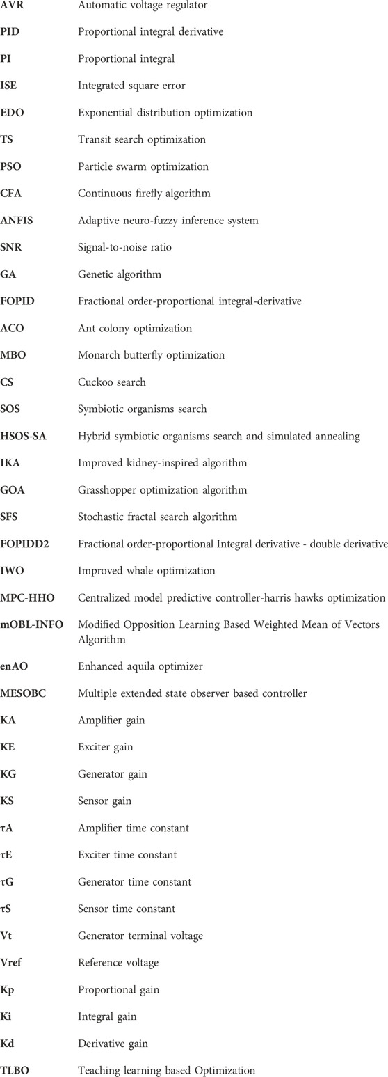
Nomenclature
Keywords: proportional integral derivative controller, automatic voltage regulator, exponential distribution optimization algorithm, transit search optimization algorithm, optimiation problem
Citation: Amin MS, Attia MA, Khamees AK, Mekhamer SF, Kotb H, AboRas KM and Yousef A (2024) Development of AVR controller performance using exponential distribution and transit search optimization techniques. Front. Energy Res. 12:1356978. doi: 10.3389/fenrg.2024.1356978
Received: 16 December 2023; Accepted: 16 February 2024;
Published: 05 March 2024.
Edited by:
Yogendra Arya, J.C. Bose University of Science and Technology, YMCA, IndiaReviewed by:
Emre Çelik, Duzce University, TürkiyeSerdar Ekinci, Batman University, Türkiye
Naladi Ram Babu, Aditya Engineering College, India
Omveer Singh, Gautam Buddha University, India
Copyright © 2024 Amin, Attia, Khamees, Mekhamer, Kotb, AboRas and Yousef. This is an open-access article distributed under the terms of the Creative Commons Attribution License (CC BY). The use, distribution or reproduction in other forums is permitted, provided the original author(s) and the copyright owner(s) are credited and that the original publication in this journal is cited, in accordance with accepted academic practice. No use, distribution or reproduction is permitted which does not comply with these terms.
*Correspondence: Kareem M. AboRas, a2FyZWVtLmFib3Jhc0BhbGV4dS5lZHUuZWc=; Amr Yousef, YS55b3VzZWZAdWJ0LmVkdS5zYQ==