 Gu Tingyun
 Zhang Houyi
- Electric Power Research Institute of Guizhou Power Grid Co., Ltd., Guiyang, Guizhou, China
Constraining the virtual inertia of variable-speed wind turbines within the variable frequency limit time will be the key to improving the wind power’s reliability in actively supporting the system frequency. First, this paper analyzes the controllable characteristics and evaluation methods of the virtual inertia of the wind turbine. Second, it quantifies the variable frequency limit time of the grid with high-proportion wind power and considers the wind turbine speed and power margin to restrict the virtual inertia of the wind turbine during the period of frequency drop or increase to provide reliable inertia support to ensure the safety of the system frequency. On this basis, the inertia demand under the frequency safety of the system was analyzed, and the virtual inertia control strategy of the variable-speed wind turbine in the variable frequency limit time was proposed using the speed tracking performance of the wind turbine. Finally, the grid with a high-proportion wind power simulation system is built to verify that the variable-speed wind turbine can reliably satisfy the inertia demand of system frequency modulation under the proposed control strategy and significantly improve its active support performance to the power grid.
1 Introduction
Improving the grid-connected support capability of wind turbines has become a key technology for enabling high-proportion wind power consumption and achieving the “30·60 carbon target.” Under maximum power tracking control, large-scale random and intermittent wind power is injected into the power grid, and the synchronous generator is unable to ensure the safe operation of the system due to the reduction of the installed proportion (Fernández-Guillamón et al., 2019; Mensou et al., 2020; Zhu et al., 2021). At present, the frequency active support control of variable-speed wind turbines has attracted much attention.
Variable-speed wind turbines can actively participate in the frequency adjustment of the power grid by adding virtual inertia and primary frequency controllers based on power tracking control (Yuan et al., 2017; Ochoa and Martinez, 2018; Yuan et al., 2018). In the early stage of frequency change, if the wind turbine does not have an inertial response, it will lead to a significant increase in the frequency change rate, and a large frequency drop or increase will seriously threaten the safety of system operation (Sun et al., 2010; Tielens and Hertem, 2016; Das et al., 2020). In order to solve the problem of low inertia in wind turbines, Fu et al. (2017) and Qi et al. (2022) defined the virtual inertia of wind turbines. Different from the constant inherent inertia of the synchronous generator, the virtual moment of inertia through additional control not only depends on the inherent inertia, initial speed, and control parameters of the wind turbine but is also closely related to the change in the system frequency, resulting in its complex and changeable characteristics while also renders it more flexible and controllable. Mauricio et al. (2009); Gautam et al. (2011); and Li et al. (2016) proposed a virtual inertia control strategy for wind turbines and used the differential link df/dt to simulate the rotor motion characteristics of synchronous generators. On this basis, ULLAH et al. (2008); Makrini et al. (2017) further added a speed recovery module to ensure the speed recovery of the wind turbine after the inertial response, avoiding the secondary frequency drop caused by excessive inertial support during system recovery. Effective inertia support can avoid large and rapid changes in frequency, and allowing for sufficient adjustment time for subsequent primary frequency modulation. In order to reduce the static deviation of the system frequency after primary frequency modulation, the same active frequency droop control as the synchronous generator was introduced into the active power control of the wind turbine. Ramtharan et al. (2007) and Zertek et al. (2012) proposed a deloading control method for wind turbines and simulated the primary frequency modulation characteristics of synchronous generators through variable pitch control. Almeida and Lopes (2007) and Zhang et al. (2012) used the overspeed control of the wind turbine to complete the deloading operation of the wind turbine and cooperated with the virtual inertia to improve the frequency modulation performance of the wind turbine. In theory, the power electronic converter gives the wind turbine flexible power control performance. However, the characteristics of virtual frequency modulation are affected by many factors, and its engineering practicability still requires to be explored.
The performance evaluation of the virtual inertia and primary frequency modulation of the wind turbine is generally difficult to solve (Wu and Infield, 2014; Zhu et al., 2018). Among them, the additional primary frequency control is relatively simple. When the load-shedding reserve capacity is sufficient, the wind turbine can have the same power distribution capability as the synchronous generator using the active power frequency droop characteristics (Vidyanandan and Senroy, 2013; Xiao et al., 2017). However, it is difficult to evaluate the virtual inertia of the wind turbine, which requires discussion at present. Because the initial wind speed determines the kinetic energy reserve of the wind turbine and the wind turbine speed will be affected by power tracking control, additional inertia control, and system frequency characteristics at the same time, the virtual inertia is always in dynamic change, which is not only complicated in quantification but also has operating risk. Ma et al. (2017); Zhu et al. (2017); and Ying et al. (2018) analyzed that although the introduction of virtual inertia can reduce the frequency change rate, it has the risk of aggravating the system power oscillation. Shi et al. (2011) and Lucas et al. (2019) used the small disturbance analysis method to prove that the virtual inertia of the wind turbine would lead to the right shift of the characteristic root and weaken the stability of the system. Reasonable quantification of virtual inertia can not only provide a basis for accurately predicting the effect of frequency active support but also be the key to evaluating the operation risk of additional control. Wen and Lin (2021) and Wang et al. (2022) proposed quantitative requirements for virtual inertia to ensure the frequency security of the grid through constraints such as frequency change rate and minimum value. However, the expected virtual inertia support is not only a prerequisite but also an urgent problem to be solved. Although the source of virtual inertia has been extended to various renewed energy sources and loads, the nonlinear time-varying characteristics make it difficult to quantify the inertia, and a reasonable time scale is urgently needed to constrain the multi-source inertia to complete the evaluation (Wen and Lin, 2021). In summary, the wind power frequency active support technology is not mature at present, and the promotion and application still lack the quantification and control methods of virtual inertia.
In order to improve the reliability of wind turbine frequency active support control according to the system frequency safety requirements, this paper proposes a quantitative method and control strategy of virtual inertia using the inertia support time and wind turbine operation characteristics constraints. First, based on the definition of virtual inertia of the wind turbine, the frequency characteristics of the wind power grid-connected system and the problems of inertia evaluation are analyzed. Second, the frequency conversion extreme time is calculated, and the wind turbine speed and power margin are considered to constrain and quantify the wind turbine virtual inertia. Third, according to the virtual inertia demand and quantitative index, the virtual inertia control strategy of the variable-speed wind turbine in the extreme time of frequency conversion is proposed by speed tracking control. Finally, a simulation system with high-proportion wind power is built to verify the improvement effect of the proposed evaluation method and control strategy on the reliability of wind turbine frequency active support.
The remainder of this paper is organized as follows: Section 2 presents the virtual inertia evaluation method for wind turbines. Section 3 presents the calculation method of frequency conversion extreme time for the system with high-proportion wind power. Section 4 presents the virtual inertia constraint and evaluation of wind turbines. Section 5 presents the virtual inertia demand and control of wind turbines. Section 6 presents the numerical results and demonstrates the effectiveness of the proposed method. Section 7 concludes the paper and presents future work.
2 Virtual inertia evaluation of the wind turbine
2.1 Wind turbine frequency active support characteristics
After the system with a high proportion of wind power encounters an active power disturbance, the system frequency support should be completed by the synchronous generator set and wind turbine. In order to improve the utilization rate of wind energy, wind farms usually do not use the deloading operation mode to reserve for primary frequency regulation. In this mode, the virtual inertial response will be the frequency active support function that wind power urgently needs. In the wind power grid-connected system, the synchronous generator and the wind turbine should jointly complete the inertial support, and the primary frequency modulation function is borne by the synchronous generator and the energy storage.
Taking a short-term frequency drop as an example, the dynamic response of wind turbines and synchronous generators participating in frequency adjustment is shown in Figure 1. In this figure, t0 is the frequency drop time, tb is the primary frequency modulation action time, tfm is the time when the frequency drops to the lowest value, and tp is the end time of the primary frequency modulation.
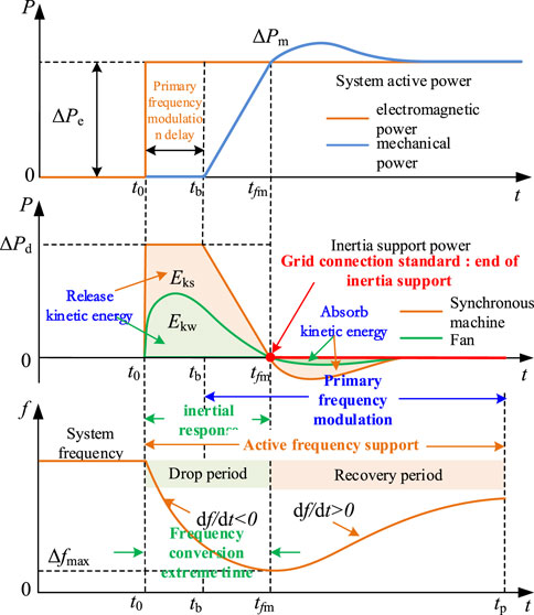
Figure 1. Power support of generators and dynamic response of system frequency.
At time t0, the load suddenly increases ΔPd, and the system frequency drops sharply. The synchronous generator set and wind turbine need to respond quickly to the frequency change, and the system power demand is compensated by the fast active power support, that is, ΔPe = ΔPd.
At the t0∼tfm stage, after the wind turbine starts the inertia support control, it will share the unbalanced power borne by the synchronous generator, thereby slowing down the system frequency drop speed. The common virtual inertia control of wind turbines adopts a differential link, and the power response is defined as Eq. (1):
where ΔPw is the wind turbine inertial support power and KI is the differential control coefficient.
As shown in Figure 1, during a frequency drop (df/dt <0), the power response of the virtual inertia controller is ΔPw >0. At this stage, the synchronous generator and the wind turbine jointly maintain the inertia support power and satisfy the load demand ΔPd. The wind turbine reduces the kinetic energy demand of the synchronous generator by releasing the kinetic energy.
At the tfm ∼ tp stage, during frequency recovery (df/dt >0), the power response of the virtual inertia controller is ΔPw <0. At this stage, the wind turbine absorbs power from the system under virtual inertia control, and the wind turbine changes from releasing kinetic energy to absorbing kinetic energy, which increases the primary frequency regulation burden of the synchronous generator and slows down the frequency recovery speed.
Considering that the virtual inertia has the problem of grid-connected security, at present, GB/T19963.1–2021 “wind farm access power system technical regulations” have stipulated that the wind turbine is required to have the inertia support function after being connected to the system, but the additional controller must satisfy the following conditions: Δf×df/dt >0. The wind turbine should set the time tfm as the end time of the virtual inertia control to satisfy the grid-connected requirements.
It is worth noting that it is necessary to detect the frequency signal at the grid-connected point of the wind turbine when determining the end tfm of the inertial support. The differential signal has high-frequency noise in the field test. Combined with the actual test situation, it is difficult to determine whether Δf × df/dt is greater than zero. In addition, at the end of the moment of inertia support, the wind turbine has released kinetic energy, resulting in a decrease in speed. After restoring to the maximum power tracking control, the output power of the wind turbine will still be lower than the initial level before the frequency drop. This is because the wind turbine speed has dropped. Therefore, even if the inertial control can be terminated in time, the wind turbine will still absorb the power, accelerate the rotor, store kinetic energy, and complete the maximum power tracking target; however, this will not be conducive to frequency recovery during primary frequency modulation.
It can be seen from Figure 1 that during the active frequency support period, the virtual inertia control of the wind turbine cannot continuously provide effective active power support for the system. Combined with the inertia start-up conditions specified in the grid-connected standard, this paper defines the effective time of the inertia response as the frequency conversion extreme time tfm; that is, after the system is disturbed, the frequency drops or increases from the initial value to the maximum frequency deviation.
Before adopting virtual inertia control, if the wind turbine can predict the extreme time of frequency conversion, it not only ensures the safe removal of the additional control and effectively avoids the misoperation caused by the large monitoring error of the frequency differential signal but also helps solve the problem of quantitative evaluation of virtual inertia, and then it provides a more reliable calculation method for the inertia demand under the system frequency safety.
2.2 Virtual inertia evaluation based on frequency conversion extremum time
The inertia of the wind power grid-connected system is composed of the inherent inertia of the synchronous generator and the virtual inertia of the wind turbine. The inertia time constant of the synchronous generator depends on the mechanical characteristics of the rotor, which can be expressed as Eq. (2) (Zhu et al., 2021)
where Jg is the mechanical moment of inertia of the synchronous generator; ωe is the synchronous speed; pg is the number of rotor poles; Ekg is the rotor kinetic energy stored at the rated speed of the synchronous generator; and Sg is the rated capacity of the synchronous generator.
Referring to the definition of the inertia time constant of a synchronous generator, the virtual inertia time constant Hvir of a variable-speed wind turbine can be expressed as (Qi et al., 2022)
where Hw is the inherent inertia time constant of the wind turbine; Δωr is the change in the wind turbine speed; ωr0 is the initial speed of the wind turbine before the inertial response; Δωe is the synchronous speed variation; pw is the number of wind turbine poles; Sw is the rated capacity of the wind turbine; and Jvir is the virtual moment of inertia of the wind turbine, which can be expressed as
where Jw is the inherent moment of inertia of the wind turbine.
According to the definition of the virtual inertia of the wind turbine in (3) and (4), it can be seen that if Δωr/Δωe >>1, the virtual inertia will be much larger than the inherent inertia of the wind turbine and even has better inertial support ability than the synchronous generator set. However, in practical control, Hvir is determined by ωr0, Hw, and Δωr/Δωe, where ωr0 depends on the real-time wind speed, which can be expressed as Eq. (5)
where λopt is the optimal tip speed ratio; v is the real-time wind speed; R is the radius of the wind wheel; ωmax is the maximum speed allowed for the stable operation of the wind turbine; vmin is the cut-in wind speed; and vmax is the maximum wind speed before the pitch control starts.
In the control process, it is necessary to comprehensively consider the dynamic changes in the inherent inertia Hw, wind speed, additional power, and system frequency of the wind turbine to obtain the effect of Δωr>>Δωe. Due to the coupling problem of multiple variables, the virtual inertia of the wind turbine can be much higher than the inherent inertia in theory, but the dynamic changes in the control process will make it difficult to predict its support performance and seriously weaken its application value.
In the current virtual inertia evaluation method, due to the real-time fluctuation of wind turbine speed and system angular frequency, Δωr/Δωe needs to be monitored in real-time. In the absence of time-scale constraints, the virtual inertia of the wind turbine will be an uncertain parameter. If reliable inertia reserves cannot be obtained, it will be impossible to predict the drop or increase in the amplitude of frequency after disturbance, which makes the key problem of frequency security early warning difficult to solve.
To solve this problem, a time scale must be introduced to constrain the virtual inertia. In this paper, the extreme time of frequency conversion is taken as the effective time of inertia response of the wind turbine. In the range of t0∼tfm, if Δωe is equal to the unit value of Δfmax, then Hvir can be expressed as
According to (6), Δωr determines the size of Hvir when other parameters are known. At this time, the virtual inertia of the wind turbine can be quantitatively evaluated according to the speed variation in the frequency conversion extreme time. Therefore, the key to evaluating the virtual inertia of the wind turbine is to calculate the extreme value time of the system frequency conversion and obtain the speed change after the inertia response of the wind turbine.
3 Frequency conversion extreme time of system with high-proportion wind power
3.1 Frequency conversion extreme time calculation
Considering the limitation of the inherent inertia of the wind turbine on the speed, as well as the real-time changes in the wind turbine speed and system frequency, not only the potential of virtual inertia control remains unclear, but there are also still many problems in quantitative evaluation. In order to solve this problem, this paper will use the frequency conversion extreme time and the wind turbine operating state to constrain the virtual inertia for quantitative evaluation. Among them, the calculation process of the system frequency conversion extreme time as a key parameter is as follows.
In the system with high-proportion wind power, the aggregation model structure of the synchronous generator set and wind turbine is shown in Figure 2. The model includes the synchronous generator, wind turbine, and load frequency response module. The parameter design of each module is shown in Table 1.
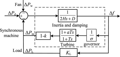
Figure 2. System frequency response aggregation model.
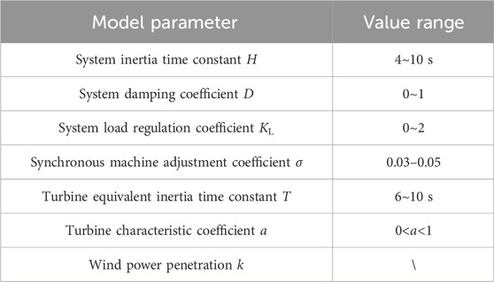
Table 1. System frequency response model parameters and value range.
According to Figure 2, the system frequency response equation can be expressed as
where ΔPm is the synchronous generator power response signal; ΔPw is the wind turbine power response signal; ΔPL is the load power response signal; and H is the system inertia time constant. Among them, ΔPm depends on the synchronous generator adjustment coefficient and turbine parameters, which can be expressed as
where ΔPL depends on the load regulation coefficient, equal to KL×Δf, and H depends on the system capacity and wind power penetration, which can be expressed as
where k is the wind power penetration and SB is the rated capacity of the system.
The system frequency variation can be calculated using (7) and expressed as
The inverse Laplace transform is applied to (10), and the system frequency response Δf(t) is
In (11), each parameter is expressed as
Without considering the power response of the wind turbine, ΔPw = 0 is taken, and ΔPd is regarded as a step disturbance. At this time, the derivative of (11) is obtained, and the extreme time of frequency conversion of the system can be expressed as
According to (11)–(13), the extreme time of frequency conversion is not only related to the inertia of conventional synchronous generators but also affected by wind power penetration and wind turbine power response. Among them, conventional synchronous generators can take typical parameter settings. The following section further discusses the influence of wind turbine-related parameters on the frequency conversion extreme time.
3.2 Influencing factors of frequency conversion extreme time
3.2.1 Wind power penetration
From (8) and (9), it can be seen that under the influence of wind power penetration, the system inertia time constant becomes Hg (1-k), and the adjustment coefficient becomes σ/(1-k); that is, wind power penetration will reduce the system inertia time constant. However, at the same time, the system adjustment coefficient is equivalently increased. When the two parameters change at the same time, the influence of the two on the frequency conversion extreme time has an offset effect. Therefore, the influence of wind power penetration on the frequency conversion extreme time is not significant. In order to verify this conclusion, the typical data in Table 1 are substituted into (12) and (13) to calculate the intermediate variables and the frequency conversion extreme time, as shown in Table 2.
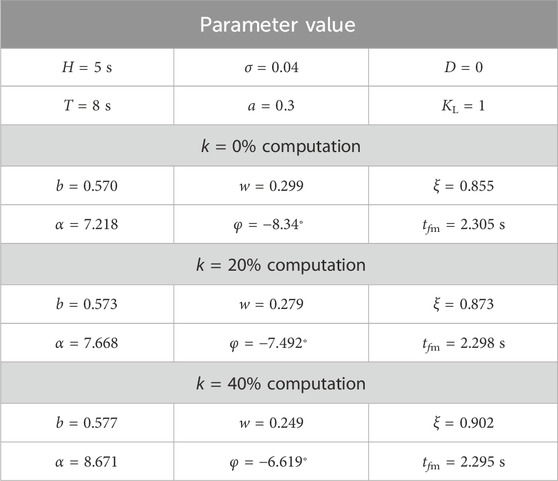
Table 2. Parameter values and calculation results of frequency expression.
The calculation results in Table 2 are brought into (11), and the power disturbance ΔPd = 0.05 pu is taken to obtain the frequency response under different wind power penetration rates, as shown in Figure 3.
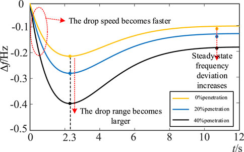
Figure 3. System frequency response curves under different wind power penetration.
It can be seen from Figure 3 that the wind power penetration rate will affect the system frequency change rate, the maximum frequency deviation, and the steady-state frequency deviation after primary frequency regulation, but it has little effect on the frequency conversion extreme time. According to the calculation results in Table 2, 2.3 s is used as the typical value for system frequency conversion extreme time in this paper.
3.2.2 Additional inertial response
In the extreme time of frequency conversion, when the inertia support potential of the wind turbine is stimulated to the maximum extent, the power response of the wind turbine can be regarded as a step change, and the power reference value will jump from the maximum power tracking control signal to the rated power or the minimum power output in a short time. Under this condition, the limit power support signal of the wind turbine can be expressed as
where Pn is the rated power of the wind turbine; Pmin is the power corresponding to the minimum speed of the stable operation of the wind turbine; and Popt is the active output power of the wind turbine under MPPT control, which can be expressed as
where kopt is the maximum power tracking coefficient and ω0 is the cut-in speed.
When ΔPw is equivalent to a step signal, its effect is equivalent to the equivalent reduction of ΔPd, and it does not affect the parameters in G(t). Therefore, the power response of the wind turbine only affects the increase and decrease in the speed of frequency and the frequency deviation extremum and does not affect the frequency conversion extremum time.
In summary, when evaluating the inertia of the wind turbine in the extreme time of frequency conversion, the calculation results of (13) can be regarded as the action time of the virtual inertia of the wind turbine. At this time, the wind turbine speed variation can be calculated by the wind turbine running state constraint, and then the virtual inertia of the wind turbine can be estimated.
4 Virtual inertia constraint and evaluation of wind turbines
4.1 Wind turbine operating state constraints
The virtual inertia of the wind turbine depends on its kinetic energy reserve and is closely related to its initial speed ωr0. In addition, the initial active power Pwe0 of the wind turbine determines the adjustment range of the power support ΔPw, which in turn affects the kinetic energy release or absorption capacity of the wind turbine.
4.1.1 Kinetic energy reserve constraint
The wind turbine energy reserve depends on the allowable value of the speed change during the frequency conversion extreme period. When the disturbance power ΔPd >0, the system has a power shortage, and the wind turbine needs to release the rotor kinetic energy; when ΔPd <0, the system has a power surplus, and the wind turbine needs to absorb energy and store it as rotor kinetic energy. Therefore, the kinetic energy reserve constraint of wind turbines can be expressed as Eq. (16)
where ΔEkwmax is the wind turbine energy reserve; ωr0 is the wind turbine speed at the beginning of the inertial response; ωmin and ωmax are the allowable minimum and maximum speeds for the stable operation of the wind turbine, respectively, usually 0.7 pu and 1.2 pu (Fu et al., 2017). Under the constraint of kinetic energy reserve, the variation range of Δωr in the frequency conversion extreme time is expressed as
where Δωrmax1 is the maximum speed variation under the constraint of kinetic energy reserve.
4.1.2 Wind turbine power constraint
In order to ensure the safe operation of the wind turbine, the support power provided by the virtual inertia control is not allowed to exceed the limit. According to (14) and (15), the wind turbine power constraint is
In the process of the inertial response, the rotor motion equation of the wind turbine can be expressed as
where Pwe is the electromagnetic power output by the wind turbine and Pwm is the mechanical power captured by the wind turbine, Pwm = koptωr03.
Combining (18) and (19), under the constraint of the rated power of the wind turbine, the variation range of Δωr in the extreme time of frequency conversion is
where Δωrmax2 is the maximum speed variation under the wind turbine power constraint.
It can be seen from (20) that the size of Δωrmax2 is determined using Hw, kopt, ωr0, and other parameters. When the capacity and type of the wind turbine are determined, Hw and kopt can be obtained, and Δωrmax2 only depends on Δωrmax2.
In order to satisfy the kinetic energy reserve constraint and the wind turbine power constraint at the same time, according to (17) and (20), the maximum speed variation of the wind turbine Δωrmax can be expressed as Eq. (21)
Taking the typical parameters of a 2 MW doubly fed wind turbine as an example, take Hw = 4 s, kopt = 1/1.23, ωmin = 0.7 pu, ωmax = 1.2 pu, and tfm = 2.3 s. According to (17), (20), and (21), Δωrmax corresponding to different initial speeds of the wind turbine under kinetic energy reserve constraints and power constraints is obtained as follows.
According to Figure 4, when ΔPd >0, the wind turbine needs to release the kinetic energy of the rotor. When the initial speed of the wind turbine is small, the kinetic energy reserve of the wind turbine is small, but the inertial support power available is large. At this time, Δωrmax is determined using the kinetic energy reserve constraint; when the initial speed of the wind turbine is large, its kinetic energy reserve is large, but the available inertial support power is small. At this time, Δωrmax is determined using the wind turbine power constraint. When the initial speed of the wind turbine is 0.905 pu, Δωrmax1 = Δωrmax2, and Δωrmax reaches the maximum of 0.205 pu at this initial speed. When ΔPd <0, when the wind turbine needs to absorb energy, the relationship between Δωrmax and speed constraint is completely opposite to that when ΔPd <0. When the initial speed of the wind turbine is small, Δωrmax depends on the power constraint of the wind turbine. When the initial speed is large, Δωrmax depends on the kinetic energy reserve constraint. When the initial speed is 1.07 pu, Δωrmax reaches the maximum of 0.13 pu.
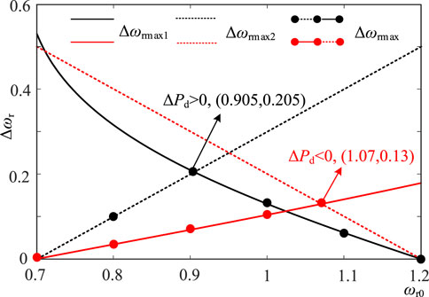
Figure 4. Evaluation results of the maximum speed variation of the wind turbine.
In summary, in the extreme time of frequency conversion, under the constraint of the wind turbine’s operating state, when ΔPd > 0, the range of rotational speed variation provided is 0–0.205 pu; when ΔPd <0, the range of rotational speed variation is 0–0.13 pu.
4.2 Virtual inertia evaluation of the wind turbine
According to (6), the virtual inertia time constant of the wind turbine also depends on Δfmax. Since the lower limit of power system frequency security is 48 Hz, the frequency deviation extremum of the system should be limited within this range after the inertial response of the wind turbine. Since the wind turbine has a fast power response capability, it can be set within the frequency safety range to complete the predetermined virtual inertia support. Therefore, Δfmax = 2 Hz is used to conservatively estimate the virtual inertia of the wind turbine.
According to the evaluation results of Section 4.1 Δωrmax, the range of the virtual inertia time constant of the wind turbine during the frequency conversion extreme time is as follows.
In the diagram, Hvirmax1 and Hvirmax2 are the maximum inertia time constants of the wind turbine under rotor kinetic energy constraint and power constraint, respectively. When the above two constraints are satisfied simultaneously, Hvirmax can be expressed as Eq. (22)
It can be seen from Figure 5 that when ΔPd > 0 and the speed of the rotor kinetic energy released by the wind turbine decreases, Hvirmax depends on the rotor kinetic energy constraint at low speeds, and Hvirmax depends on the wind turbine power constraint at high speeds. The Hvirmax range is 0–18.61 s; when ΔPd<0, when the wind turbine absorbs energy and the speed increases, Hvirmax depends on the wind turbine power constraint at low speed, and Hvirmax depends on the rotor kinetic energy constraint at high speed. The Hvirmax range is 0–13.85 s.
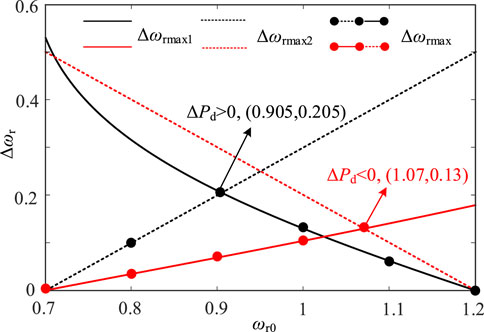
Figure 5. Evaluation results of the maximum virtual inertia of the wind turbine.
However, Δfmax in the actual response process of the system is related to the disturbance power. When the disturbance power is small, Δfmax will be less than 2 Hz, and Hvirmax of the wind turbine will be greater than the evaluation result, which can ensure that the wind turbine has a credible inertial support capability.
According to the above analysis, the wind turbine can show strong inertial support performance in a short time by changing the rotational speed through additional control. In theory, the wind turbine can cope with large power disturbances and has frequency support potential. In the actual control process, a large change in the speed in a short time will bring about problems such as power overshoot, increased mechanical load, and difficulty in speed recovery. Therefore, the wind turbine should perform an inertial response under the premise of considering the system’s inertia demand.
5 Virtual inertia demand and control of wind turbines
5.1 Virtual inertia requirements
The inertia of the wind power high-proportion system is significantly reduced, and the virtual inertia of the wind turbine should be set according to the system frequency safety requirements. At present, foreign research has put forward relevant standards for microgrid island operation, requiring that the system frequency change rate (df/dt) is not higher than ±0.5 Hz/s (Wang et al., 2022). The maximum frequency change rate of the system occurs at the initial stage of the power disturbance. The primary frequency modulation has not yet acted, and the unbalanced power of the rotor side of the synchronous machine is the largest. At this time, the system frequency change rate can be expressed as Eq. (23)
According to the above formula, when the frequency change rate constraint is determined, the system inertia requirement can be expressed as
where Hmin is the minimum inertia requirement of the system.
When the wind turbine provides virtual inertia, the inertia time constant of the system with a high proportion of wind power can be further expressed using (9) as
Combining (24) and (25), the inertia demand of the wind turbine is expressed as
Taking Hg = 5s and (df/dt)max = ±0.5 Hz/s, the virtual inertia requirement of the wind turbine is calculated using the brought-in (26), as shown in Figure 6.
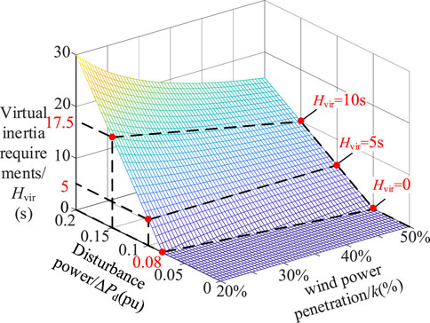
Figure 6. Wind turbine virtual inertia demand assessment results.
It can be seen from Figure 6 that the demand of system frequency security for the virtual inertia for the wind turbine mainly depends on disturbance power and wind power penetration. When the disturbance power is small and the wind power penetration rate is low, only the synchronous machine inertia Hg can meet the system inertia demand. When the permeability is lower than 20%, the inertia of the synchronous machine can cope with more than 8% of the disturbance. However, with the increase in wind power penetration, the ability of the system to cope with power disturbances is gradually weakened. When the wind power penetration reaches 50%, the system can cope with disturbances of less than 5%, which is not enough to cope with typical faults. At this time, the wind turbine should provide the necessary inertial support according to the system requirements. The inertia demand of the system increases with the increase in power disturbance. Under the same power disturbance, the virtual inertia demand of the wind turbine can be calculated according to the wind power penetration rate. When ΔPd = 0.15 pu, the system inertia requirement is 7.5 s. When k = 20%, the wind turbine needs to provide 17.5 s of virtual inertia to make the total inertia of the system reach 7.5 s. When k = 50%, the wind turbine needs to provide 10 s of virtual inertia to make the total inertia of the system reach 7.5 s.
5.2 Virtual inertia control strategy
Combined with the system frequency safety requirements, the wind turbine can use its speed tracking performance to complete the virtual inertial support within the frequency conversion extreme time. The structure of the wind turbine virtual inertia controller proposed in this paper is shown in Figure 7, which consists of two modules: virtual inertia control and virtual inertia evaluation. Among them, the virtual inertia evaluation module has two evaluation functions: the maximum inertia of the wind turbine and the system inertia demand.
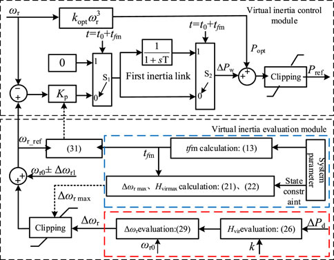
Figure 7. Wind turbine virtual inertia controller structure.
In the wind turbine virtual inertia evaluation module, the maximum speed variation and maximum inertia are evaluated according to the operating state and frequency conversion extreme time constraint, which are used as the limiting conditions of the wind turbine inertia demand and speed variation demand evaluation results. For the evaluation of the wind turbine’s virtual inertia demand, according to (26), disturbance power and wind power permeability can be introduced to calculate the wind turbine’s inertia demand. According to the evaluation results of the wind turbine’s inertia demand, the wind turbine’s speed demand can be calculated. The specific analysis is as follows:
The real-time equivalent inertia time constant Hvir in the process of wind turbine inertia response can be expressed as
In the extreme time of frequency conversion, both sides of (27) are integrated at the same time to obtain
where Δfmax is the frequency deviation value corresponding to tfm, which can be calculated according to (11) under the assumption that the system inertia meets the demand. According to the calculation results, the simultaneous formulas (19) and (28) are solved, and the rotational speed variation that meets the inertia demand of the wind turbine can be expressed as
According to the above formula, the required speed variation Δωr of the wind turbine at different initial speeds can be obtained by introducing the operating state parameters and inertia requirements of the wind turbine. Then, within tfm time, wind turbine corresponding speed can be calculated as ωr1 = Δωr+ωr0.
The wind turbine virtual inertia control module generates additional power signals through speed tracking control to make the wind turbine track the reference speed in real-time, and the reference speed ωr_ref is set according to ωr1. First, in order to ensure that the wind turbine speed can change from ωr0 to ωr1 within tfm, the speed-tracking control principle based on the wind turbine rotor motion equation is designed as follows:
where Kp is the speed-tracking controller parameter.
According to (30), the value of Kp in tfm can be calculated as
where ωr_ref = ωr1±Δωr1 and Δωr1 is the speed change margin.
According to (31), the value of Kp can be calculated to realize the change in the wind turbine speed from ωr0 to ωr1 in tfm to realize the quantitative control of the wind turbine speed.
Second, in order to ensure the smooth exit of the inertial support power of the wind turbine after the tfm moment, the first-order inertial link is introduced, as shown in Figure 7. When the wind turbine speed changes to ωr1 at t0+tfm, the switches S1 and S2 switch from 0 to 1, and the speed tracking control exits through the first-order inertia link. Under the above control, the wind turbine inertial support power signal can be expressed as
where T is the first-order inertial link time parameter, taking 5 s.
Under the control of (32), the inertial support power of the wind turbine is the largest at the initial moment of disturbance, which can effectively suppress the frequency change rate. After the frequency reaches the extreme point, the rotational speed changes to the demand evaluation value ωr1, and the smooth exit of the inertial support power is realized under the action of the first-order inertial link.
6 Simulation verification
6.1 Simulation system
In order to verify the effectiveness of the virtual inertia evaluation and control method of the wind turbine proposed in this paper, the IEEE-9 bus system (None, 2015) with high-proportion wind power shown in Figure 8 is built using DIgSILENT/PowerFactory simulation software. The test system includes three thermal power plants (G1, G2, and G3) and a wind farm (DFIG), which can change the wind power penetration by adjusting the capacity of thermal power units and wind turbines. Assuming that the wind speed remains unchanged at 8 m/s, the main parameters of the system are shown in Table 3. The load mutation occurs when t0 = 2.0 s.

Figure 8. Simulation model of the wind power high permeability system.
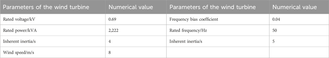
Table 3. System parameters.
6.2 Frequency conversion extreme time verification
In order to verify the correctness of the frequency conversion extreme time theory calculation, the test system adopts the following parameter settings to analyze the frequency response characteristics after disturbance.
As shown in Table 4, in example 1, the wind power penetration rate in the test system is k = 20%. At the period of 2.0 s, the power disturbance is encountered, and the variation is ΔPd = 0.06 pu. According to Figure 6, the inherent inertia of the synchronous machine can meet the system frequency safety requirements, and the wind turbine is not required to provide virtual inertia. When the wind turbine is not controlled by virtual inertia, the dynamic response of system frequency and synchronous machine power is shown in Figure 9.
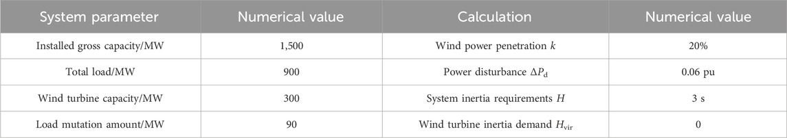
Table 4. Parameter setting of simulation example 1
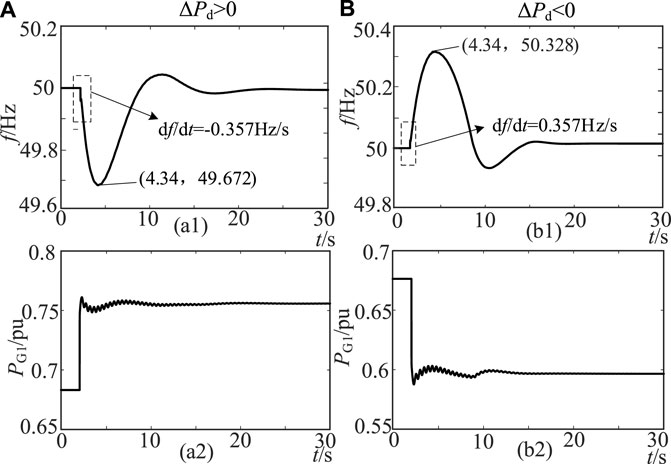
Figure 9. (a1): The change curve of frequency with time ΔPd > 0. (a2): The change curve of PG with time ΔPd > 0. (b1):The change curve of frequency with time ΔPd < 0. (b2):The change curve of PG with time ΔPd < 0.
As shown in Figure 9, the synchronous machine responds to frequency changes by increasing/decreasing power when the load changes suddenly. The simulation results of Figure 9 are compared with the theoretical calculation results, as shown in Table 5.
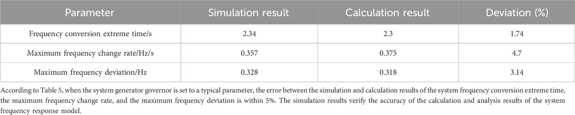
Table 5. Calculation results of simulation examples.
6.3 Frequency modulation effect comparison of virtual inertia control
In order to verify the frequency modulation effect of the virtual inertia control strategy proposed in this paper, the power disturbance is increased and compared with the commonly used differential control. The system parameters in example 2 are set as Table 6:
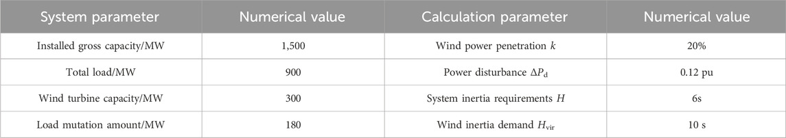
Table 6. Parameter setting of simulation example 2.
In example 2, the load disturbance variation increases to 180 MW. The test system uses formula (26) to analyze the frequency safety, and the demand for the virtual inertia of the wind turbine is 10 s. In order to meet the needs of inertial support, the wind turbine adopts the following two control strategies for comparison: 1) when differential control is adopted, KI is 20 to meet the inertia demand; 2) when the proposed control is adopted, speed tracking is used. According to the formula (27), when ΔPd > 0 and ΔPd < 0, the required speed changes in the wind turbine are 0.03 pu and 0.029 pu, respectively, and the Kp values obtained using formula (30) are 3.2 and 3.3, respectively. Under the two control strategies, the dynamic response of the system is shown in Figures 10, 11.
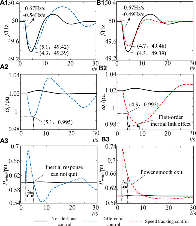
Figure 10. (A1):The first case using differential control. (A2):The second case using differential control. (A3):The third case using differential control. (B1):The first case using speed tracking control. (B2):The second case using speed tracking control. (B3):The third case using speed tracking control.
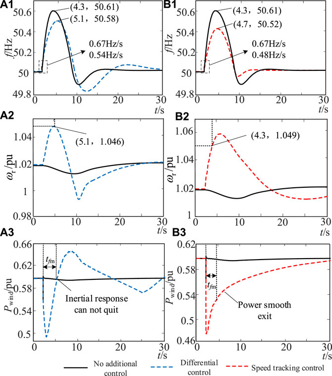
Figure 11. (A1):The first case using differential control. (A2):The second case using differential control. (A3):The third case using differential control. (B1):The first case using speed tracking control. (B2):The second case using speed tracking control. (B3):The third case using speed tracking control.
As shown in Figure 10, without additional control, the wind turbine hardly responds to frequency changes. The maximum frequency drop amplitude of the system Δfmax is −0.61 Hz, and the maximum frequency change rate (df/dt)max is −0.67 Hz/s, which has exceeded the allowable value of frequency safety.
When the differential control is adopted, the speed change in the wind turbine is 0.025 pu within the frequency conversion extreme time tfm, and the maximum frequency change rate (df/dt)max and the drop amplitude Δfmax of the system are reduced to −0.54 Hz/s and −0.58 Hz, respectively, but still do not meet the maximum frequency change rate constraint. The Hvir value of the wind turbine in tfm is 8.79 s, which does not meet the inertia demand of the wind turbine under this example. In addition, since the differential control cannot exit at tfm, the overshoot occurs during the frequency recovery process, which is not conducive to frequency security and stability.
When the control strategy proposed in this paper is adopted, the wind turbine speed variation is 0.028 pu, the system frequency change rate (df/dt)max and the drop amplitude Δfmax are reduced to −0.49 Hz/s and −0.52 Hz, respectively, and Hvir of the wind turbine within tfm is 10.98 s, which meets the system‘s demand for virtual inertia. According to Figure 10(b1)∼(b3), the smooth exit of the inertial support power of the wind turbine can be realized in the speed tracking control, which reduces the overshoot in the system frequency recovery process. In addition, under the action of the first-order inertial link, the inertial support power of the wind turbine is reduced to 0 after experiencing delay, and the speed begins to recover later, which avoids the wind turbine absorbing power in the frequency recovery stage and is conducive to system frequency recovery. The frequency modulation effect is better than the traditional differential control.
Similarly, when ΔPd <0, the wind turbine speed variation under differential control is 0.026 pu, the system frequency change rate (df/dt)max and the drop amplitude Δfmax are reduced to 0.54 Hz/s and 0.58 Hz, respectively. The Hvir value of the wind turbine within tfm is 9.14 s, which does not meet the inertia demand of the wind turbine under this example; under the control strategy proposed in this paper, the wind turbine speed variation is 0.029 pu, and the system frequency change rate (df/dt)max and the drop amplitude Δfmax are reduced to 0.48 Hz/s and 0.52 Hz, respectively. The Hvir value of the wind turbine within tfm is 11.37 s, which meets the system’s demand for virtual inertia.
In summary, in both cases of ΔPd > 0 and ΔPd < 0, the proposed control can make the wind turbine show a virtual inertia that meets the system requirements within tfm by tracking the speed and can achieve a smooth exit of the inertial support power after tfm, avoiding frequency overshoot. The test results show that compared with the current differential control, the inertial support proposed in this paper aims to meet the inertia requirements of the system and combines the virtual inertia constraint of the wind turbine to complete the design of control parameters, which is more conducive to the reliability of the wind turbine to improve frequency support.
6.4 Evaluation and verification of the maximum inertia of the wind turbine
In order to further test the maximum inertia performance of the wind turbine under the operating state constraints, we will further increase the power disturbance and improve the wind power penetration rate; the system parameters in example 3 are set as Table 7:
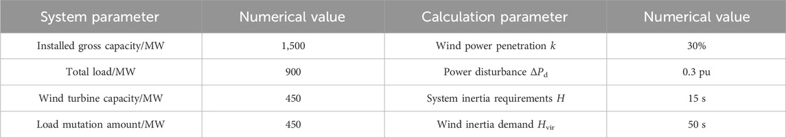
Table 7. Parameter setting of simulation example 3.
In example 3, the wind power penetration rate is increased to 30%, and the disturbance variation reaches 450 MW. In order to ensure that the system frequency change rate meets the constraints, the test system’s inertia requirement is set to 15 s, and the virtual inertia requirement of the wind turbine is set to 50 s. In this case, the inertia demand of the system is far greater than the maximum virtual inertia that the wind turbine can provide, so the wind turbine should provide the maximum inertia support according to the initial operating state during the frequency conversion extreme time. By changing the wind speed, the initial speed of the wind turbine is set to 0.8 pu and 1.1 pu, and the dynamic response of the system frequency, wind turbine speed, and power output is obtained when ΔPd > 0 and ΔPd < 0, as shown in Figures 12–15.
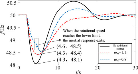
Figure 12. Frequency response when ΔPd > 0.
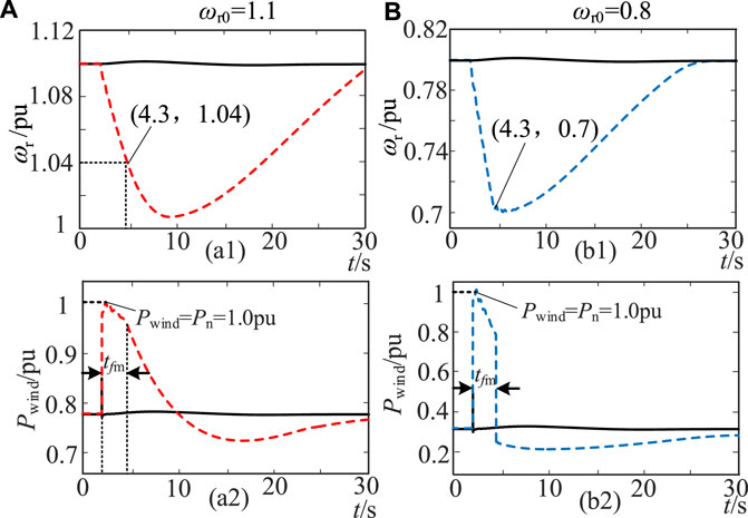
Figure 13. (a1):The first case when it is wro=1.1. (a2):The second case when it is wro=1.1. (b1):The first case when it is wro=0.8. (b2):The second case when it is wro=0.8.
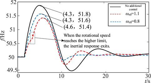
Figure 14. Frequency response when ΔPd < 0.
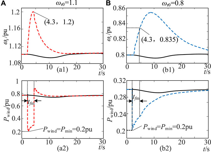
Figure 15. (a1):The first case when it is wro=1.1. (a2):The second case when it is wro=1.1. (b1):The first case when it is wro=0.8. (b2):The second case when it is wro=0.8.
When the initial speed of the wind turbine is 1.1 pu, the theoretical analysis of Figures 4, 5 shows that the maximum speed change in the wind turbine in tfm is 0.062 pu and the maximum inertia is 7.44 s. As shown in Figure 13, when ΔPd > 0, although the kinetic energy of the rotor that the wind turbine can release is large, due to the power constraint, the speed change in the wind turbine during the frequency conversion extreme time is only 0.06 pu, which can increase the maximum frequency deviation by 0.3 Hz. The maximum inertia Hvir = 7.56 s, allows for the smooth exit of wind turbine inertial support after the frequency conversion extreme moment, under the action of the first-order inertial link.
When the initial speed of the wind turbine is ωr0 = 0.8 pu, the maximum speed change in the wind turbine in tfm is 0.1 pu and the maximum inertia is 8 s. As shown in Figure 13, due to the constraint of the rotor kinetic energy reserve, the inertia response of the wind turbine immediately exits after the speed of the wind turbine drops to the minimum value of 0.7 pu at the extreme time of frequency conversion, which will cause a secondary drop in frequency. However, due to the large inertial support power available at this speed, the maximum frequency deviation can be increased by 0.4 Hz, and the maximum inertia of the wind turbine during the extreme time of frequency conversion is Hvir = 10 s.
Similarly, when ΔPd <0, it can be seen from Figures 4, 5 that the theoretical values of the maximum speed change in the wind turbine within tfm are 0.1 pu and 0.034 pu at the initial speeds of 1.1 pu and 0.8 pu, respectively. The maximum inertia is 12 s and 2.75 s, respectively.
According to the test results in Figures 14, 15, when ωr0 = 1.1 pu, due to the constraint of the rotor kinetic energy reserve, the inertia response of the wind turbine increases to 1.2 pu and the frequency continues to increase. However, due to the large inertial support power provided by the wind turbine, the maximum frequency deviation can be reduced by 0.4 Hz, and the maximum inertia Hvir = 13.75 s. When ωr0 = 0.8 pu, due to the small inertial support power provided by the wind turbine, the speed change in the wind turbine is 0.035 pu in the extreme time of frequency conversion, which can reduce the maximum frequency deviation by 0.2 Hz, and the maximum inertia Hvir = 3.5 s.
In summary, when the wind turbine needs to provide the maximum inertia support in the face of large disturbances, for the two cases of ΔPd > 0 and ΔPd< 0, the maximum speed variation of the wind turbine within tfm under the constraint of the operating state is basically consistent with the theoretical analysis results in this paper. Since Δfmax is lower than 2 Hz under this disturbance, the maximum inertia of the wind turbine is slightly larger than the conservative evaluation result at Δfmax = 2 Hz, as shown in Figure 5. The simulation test results verify the accuracy of the maximum inertia evaluation analysis method of the wind turbine proposed in this paper.
7 Conclusion
In order to solve the problem of evaluation and control of the virtual inertia of the wind turbine, this paper proposes the constraint and control method of the virtual inertia in the extreme time of frequency conversion, which is beneficial to improving the frequency active support performance of the wind turbine. The following conclusions are obtained through theoretical analysis and simulation verification:
1) The virtual inertia obtained by the rapid adjustment of the active power of the wind turbine is closely related to many factors, such as frequency change and its own operating state. The dynamic change in virtual inertia in the process of frequency support will greatly increase the difficulty of system frequency safety warning, and it is impossible to accurately predict the control effect.
2) In this paper, the frequency response model of the wind power grid-connected system is established, and the calculated frequency conversion extreme time is introduced into the virtual inertia evaluation. Combined with the wind turbine speed and power output state, the virtual inertia constraint is completed, which can provide more reliable inertia support data for the wind turbine frequency response.
3) Within the allowable range of the system frequency change rate, this paper evaluates the inertia requirements of the system and proposes a virtual inertia control method within the frequency conversion extreme time using the wind turbine speed tracking control performance. The test results show that the proposed control meets the support requirements of the system frequency more reliably and avoids the secondary fluctuation of frequency caused by inertia overshoot.
Data availability statement
The original contributions presented in the study are included in the article/Supplementary Material; further inquiries can be directed to the corresponding author.
Author contributions
GT: conceptualization, validation, and writing–original draft. ZH: data curation and writing–review and editing. LB: methodology and writing–original draft. MJ: project administration and writing–review and editing. FaQ: formal analysis and writing–review and editing. XY: resources and writing–review and editing. FeQ: investigation and writing–original draft.
Funding
The author(s) declare that no financial support was received for the research, authorship, and/or publication of this article.
Conflict of interest
Authors GT, ZH, LB, MJ, FaQ, XY, and FeQ were employed by Electric Power Research Institute of Guizhou Power Grid Co., Ltd.
Publisher’s note
All claims expressed in this article are solely those of the authors and do not necessarily represent those of their affiliated organizations, or those of the publisher, the editors, and the reviewers. Any product that may be evaluated in this article, or claim that may be made by its manufacturer, is not guaranteed or endorsed by the publisher.
References
Almeida, R. G., and Lopes, J. A. P. (2007). Participation of doubly fed induction wind generators in system frequency regulation. IEEE Trans. Power Syst. 22 (3), 944–950. doi:10.1109/tpwrs.2007.901096
Das, K., Guo, F., Nuño, E., and A. Cutululis, N. (2020). Frequency stability of power system with large share of wind power under storm conditions. J. Mod. Power Syst. Clean Energy 8 (2), 219–228. doi:10.35833/mpce.2018.000433
Fernández-Guillamón, A., Gómez-Lázaro, E., Muljadi, E., and Molina-García, Á. (2019). Power systems with high renewable energy sources: a review of inertia and frequency control strategies over time. Renew. Sustain. Energy Rev. 115, 109369. doi:10.1016/j.rser.2019.109369
Fu, Y., Zhang, X., Hei, Y., and Wang, H. (2017). Active participation of variable speed wind turbine in inertial and primary frequency regulations. Electr. Power Syst. Res. 147, 174–184. doi:10.1016/j.epsr.2017.03.001
Gautam, D., Goel, L., Ayyanar, R., Vittal, V., and Harbour, T. (2011). Control strategy to mitigate the impact of reduced inertia due to doubly fed induction generators on large power systems. IEEE Trans. Power Syst. 26 (1), 214–224. doi:10.1109/tpwrs.2010.2051690
Li, P., Hu, W., and Rui, H. (2016). “The integrated control strategy for primary frequency control of DFIGs based on virtual inertia and pitch control[C],” in Innovative Smart Grid Technologies-ASIA, IEEE, Melbourne, Australia, 28 November - 1 December 2016.
Lucas, E., Campos-Gaona, D., and Anaya-Lara, O. (2019). Assessing the impact of DFIG synthetic inertia provision on power system small-signal stability. Energies 12 (18), 3440. doi:10.3390/en12183440
Ma, J., Qiu, Y., Li, Y., Zhang, W., Song, Z., and Thorp, J. S. (2017). Research on the impact of DFIG virtual inertia control on power system small-signal stability considering the phase-locked loop:. IEEE Trans. Power Syst. 32 (3), 2094–2105. doi:10.1109/tpwrs.2016.2594781
Makrini, A. E., Karkri, Y. E., Boukhriss, Y., et al. (2017). LVRT control strategy of DFIG based wind turbines combining passive and active protection. Int. J. Renew. Energy Res. 7 (3), 1258–1269.
Mauricio, J. M., Marano, A., Expósito, A. G., and Martinez Ramos, J. (2009). Frequency regulation contribution through variable-speed wind energy conversion systems. IEEE Trans. Power Syst. 24 (1), 173–180. doi:10.1109/tpwrs.2008.2009398
Mensou, S., Essadki, A., Nasser, T., and Bououlid Idrissi, B. (2020). A direct power control of a DFIG based WECS during symmetrical voltage dips. Prot. Control Mod. Power Syst. 5 (1), 5–47. doi:10.1186/s41601-019-0148-y
None (2015). Definition and classification of power system stability IEEE/CIGRE joint task force on stability terms and definitions. Gold. Res. Thoughts 4 (3), 1387–1401.
Ochoa, D., and Martinez, S. (2018). Frequency dependent strategy for mitigating wind power fluctuations of a doubly-fed induction generator wind turbine based on virtual inertia control and blade pitch angle regulation. Renew. Energy 128 (PT.A), 108–124. doi:10.1016/j.renene.2018.05.047
Qi, X., Madonski, R., Huang, C., and Ke, Y. (2022). Tracking-differentiator-based dynamic virtual inertial control of offshore wind power plant for frequency regulation. Int. J. Electr. power energy Syst. 141, 108150. doi:10.1016/j.ijepes.2022.108150
Ramtharan, G., Ekanayake, J. B., and Jenkins, N. (2007). Frequency support from doubly fed induction generator wind turbines. IET Renew Power Gener 1 (1), 3–9. doi:10.1049/iet-rpg:20060019
Shi, L. B., Wang, C., Yao, L. Z., and Ni, Y. X. (2011). Analysis of impact of grid-connected wind power on small signal stability. Wind Energy 14 (4), 517–537. doi:10.1002/we.440
Sun, Y., Wang, L., and Li, G. (2010). “A review on analysis and control of small signal stability of power systems with large scale integration of wind power,” in International Conference on Power System Technology, IEEE, Zhejiang, Hangzhou, China, 24-28 October 2010.
Tielens, P., and Hertem, D. V. (2016). The relevance of inertia in power systems. Renew. Sustain. Energy Rev. 55, 999–1009. doi:10.1016/j.rser.2015.11.016
Ullah, N. R., Thiringer, T., and Karlsson, D. (2008). Temporary primary frequency control support by variable speed wind turbines— potential and applications. IEEE Trans. Power Syst. 23 (2), 601–612. doi:10.1109/tpwrs.2008.920076
Vidyanandan, K. V., and Senroy, N. (2013). Primary frequency regulation by deloaded wind turbines using variable droop. IEEE Trans. Power Syst. 28 (2), 837–846. doi:10.1109/tpwrs.2012.2208233
Wang, B., Sun, H., and Wenfeng, L. (2022). Minimum inertia estimation of power system considering dynamic frequency constraints. Proc. CSEE 42 (1), 114–127.
Wen, Y., and Lin, X. (2021). Minimum inertia requirement assessment of microgrids in islanded and grid-connected modes. Proc. CSEE 41 (6), 2040–2053.
Wu, L., and Infield, D. (2014). Power system frequency management challenges-a new approach to assessing the potential of wind capacity to aid system frequency stability. IET Renew. Power Gener. 8 (7), 733–739. doi:10.1049/iet-rpg.2013.0424
Xiao, W., Gao, W., Scholbrock, A., Muljadi, E., Gevorgian, V., Wang, J., et al. (2017). Evaluation of different inertial control methods for variable-speed wind turbines simulated by fatigue, aerodynamic, structures and turbulence (FAST). IET Renew. Power Gener. 11 (12), 1534–1544. doi:10.1049/iet-rpg.2017.0123
Ying, J., Yuan, X. M., Hu, J. B., and He, W. (2018). Impact of inertia control of DFIG-based WT on electromechanical oscillation damping of SG. IEEE Trans. Power Syst. 33 (3), 3450–3459. doi:10.1109/tpwrs.2018.2801283
Yuan, F., Wang, Y., and Zhang, X. (2017). Integrated wind turbine controller with virtual inertia and primary frequency responses for grid dynamic frequency support. IET Renew. Power Gener. 11 (8), 1129–1137. doi:10.1049/iet-rpg.2016.0465
Yuan, T., Wang, J., Guan, Y., Liu, Z., Song, X., Che, Y., et al. (2018). Virtual inertia adaptive control of a doubly fed induction generator (DFIG) wind power system with hydrogen energy storage. Energies 11 (4), 904. doi:10.3390/en11040904
Zertek, A., Verbic, G., and Pantos, M. (2012). Optimised control approach for frequency-control contribution of variable speed wind turbines. IET Renew. Power Gener. 6 (1), 17–23. doi:10.1049/iet-rpg.2010.0233
Zhang, Z. S., Sun, Y. Z., Lin, J., and Li, G. J. (2012). Coordinated frequency regulation by doubly fed induction generator-based wind power plants. IET Renew Power Generation 6 (1), 38–47. doi:10.1049/iet-rpg.2010.0208
Zhu, X., Chen, Y., Zhang, X., et al. (2017). Impact of wind turbine on power oscillation characteristic in region network and integrated control strategy. Electr. Meas. Instrum. 54 (1), 33–38.
Zhu, X. H., Xie, Y., and Zhu, H. (2018). Review on power system frequency regulation with high wind power permeability. Energy Power Eng. 10 (8), 366–382. doi:10.4236/epe.2018.108023
Keywords: wind power generation, virtual inertia, frequency support, rotor speed tracking, power grid
Citation: Tingyun G, Houyi Z, Bowen L, Junyi M, Qiang F, Yutao X and Qihui F (2024) Virtual inertia control to active support of the variable-speed wind turbine in variable frequency limit time. Front. Energy Res. 12:1352385. doi: 10.3389/fenrg.2024.1352385
Received: 08 December 2023; Accepted: 27 March 2024;
Published: 01 May 2024.
Edited by:
Yaser Qudaih, Higher Colleges of Technology, United Arab EmiratesReviewed by:
Mansoor Janjua, Higher Colleges of Technology, United Arab EmiratesGaber Magdy, Aswan University, Egypt
Copyright © 2024 Tingyun, Houyi, Bowen, Junyi, Qiang, Yutao and Qihui. This is an open-access article distributed under the terms of the Creative Commons Attribution License (CC BY). The use, distribution or reproduction in other forums is permitted, provided the original author(s) and the copyright owner(s) are credited and that the original publication in this journal is cited, in accordance with accepted academic practice. No use, distribution or reproduction is permitted which does not comply with these terms.
*Correspondence: Gu Tingyun, Z3V0aW5neXVuQDEyNi5jb20=