 Depin Feng1
 Weiqi Meng
- 1Linyi Power Supply Company of State Grid Shandong Electric Power Company, Linyi, China
- 2Yinan Power Supply Company of State Grid Shandong Electric Power Company, Linyi, China
- 3School of Electrical and Information Engineering, Tianjin University, Tianjin, China
The single-phase three-leg unified power quality conditioner (UPQC) can achieve the functions of voltage compensation, reactive power compensation, and harmonic compensation. However, traditional control algorithms require a phase-locked loop to obtain the real-time phase angle of the grid voltage, which undoubtedly increases algorithm complexity. To simplify the phase-locked calculation, this paper proposes a control method without the phase-locked loop for the single-phase three-leg UPQC. In the proposed scheme, the instantaneous value of the grid voltage is employed to realize the grid integration control. Then, the load voltage reference is calculated in real time using a second-order generalized integrator. Moreover, a simple algorithm for reactive power and harmonic compensation is discussed, further simplifying the control algorithm. Finally, a small-scale experimental platform is built, and the effectiveness of the proposed method is verified by the experimental results.
1 Introduction
With the popularization of large-scale distributed renewable energy generation and the addition of disruptive and non-linear loads, the power quality of the grid side in distribution networks is facing severe challenges (Sun et al., 2013; He et al., 2015; Zhang et al., 2022a). Voltage fluctuations and harmonic problems, as the typical representatives of power quality issues, not only affect the safe and stable electricity consumption of power users but also add significant costs to power transmission and distribution (Moeini et al., 2018; He et al., 2020; Wang and Yang, 2023).
As a series-parallel hybrid power quality compensation device, the unified power quality conditioner (UPQC) is widely utilized to improve the power quality of the grid side. This equipment can address current-related power quality issues in distribution systems through its parallel compensation terminal (Lakshmi and Ganguly, 2019; Silva et al., 2020). Moreover, the voltage-related power quality issues can also be addressed through its series compensation terminal. Compared to the traditional isolated single-phase four-leg topology, the single-phase three-leg UPQC topology can eliminate the isolation transformer and reduce the number of legs for a low cost. Importantly, the lack of components does not compromise the effectiveness of power quality control. Therefore, this topology has gained widespread attention in recent years (Lu et al., 2016; Abdalaal and Ho, 2021).
In traditional control methods of the UPQC, the real-time phase angle of the grid voltage needs to be obtained through a phase-locked loop (PLL). First, the parallel compensation terminal requires the real-time phase angle of the grid voltage for grid integration (Cheng and Lee, 2006; He et al., 2019). Second, the series compensation terminal needs the real-time phase angle of the grid voltage to obtain an accurate compensation voltage reference (Srinivas et al., 2019). Moreover, the extraction of reactive current and harmonic current from the system also relies on the real-time phase angle of the grid voltage (Zhang et al., 2022b; Xia et al., 2022). However, the PLL not only increases the complexity of the control algorithm but also fails to respond promptly to phase variations in the grid voltage, leading to overcurrent issues in the compensation device (Mishra and Lal, 2022; Mohammed et al., 2023).
To overcome these previously discussed disadvantages, a control method without the PLL is proposed for the single-phase three-leg UPQC in this paper. Different from the traditional method, the proposed method utilizes the instantaneous value of the grid voltage for grid integration. Then, the real-time amplitude of the grid voltage is obtained through a second-order generalized integrator and the compensation voltage reference is calculated. Additionally, the proposed method uses the load current as a reference for the parallel inverter output, eliminating the need for the extraction of reactive current and harmonic currents. Then, the compensation of the reactive and harmonic power can be realized. The subsequent sections of this article analyze the proposed control method in the frequency domain using a coordinated control system. In addition, the feasibility and effectiveness of the proposed method through experiments is validated through the experimental results.
2 The proposed control method for the single-phase three-leg UPQC
2.1 The topology structure of the single-phase three-leg UPQC
This paper begins by providing a brief introduction to the topology of the single-phase three-leg UPQC. As shown in Figure 1, the parallel compensation port consists of leg a, leg b, and parallel interface filters (Lp1, Lp2, and Cp), while the series compensation port consists of leg b, leg c, and series interface filters (Ls and Cs). When the grid voltage Vg is not equal to the rated voltage VN, the series compensation voltage Vsc will be provided through the series compensation port. As a result, the load voltage VL can reach its rated value. Additionally, the series compensation port can compensate for the harmonic components of the grid voltage. The device also compensates for the harmonic currents generated by non-linear loads by providing the parallel compensation current Ipc through the parallel compensation terminal. Then, the grid current Ig can be sinusoidal. In addition, the reactive power component of the load current can be compensated through this single-phase three-leg UPQC. The two converters share a DC bus capacitor Cdc, and the DC bus voltage Vdc is controlled using a parallel compensator.
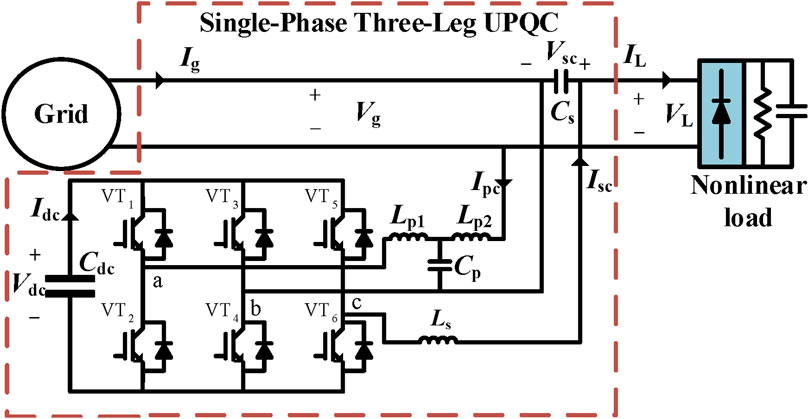
FIGURE 1. Diagram of the single-phase three-leg UPQC topology.
2.2 Parallel compensation control method
There are three control objectives for the parallel compensation terminal, including stabilizing the DC bus voltage, compensating for the load reactive current, and compensating for the load harmonic current. Therefore, the control strategy needs to be individually formulated around these three control objectives.
For the control of the DC bus voltage, first, the differential equation of the DC bus capacitor is derived as follows:
where Idc represents the current flowing into the DC bus. Therefore, the expression of the DC bus voltage can be obtained from Eq. (1)
According to Kirchhoff’s current law, it can be known that Idc = Ipc. However, the reactive component of Ipc only causes a ripple voltage at twice the frequency on the DC bus, while its active component Ipc,d plays a role in stabilizing the DC bus voltage. By designing a controller based on Eq. (2), the stability of the DC bus capacitor voltage can be achieved by controlling the active component Ipc,d of the parallel compensating current. The control strategy for Ipc,d is as follows:
where kp,dc represents the proportional coefficient of the PI controller and ki,dc represents the integral coefficient of the PI controller. The overall control block diagram of the entire control system is shown in Figure 2.
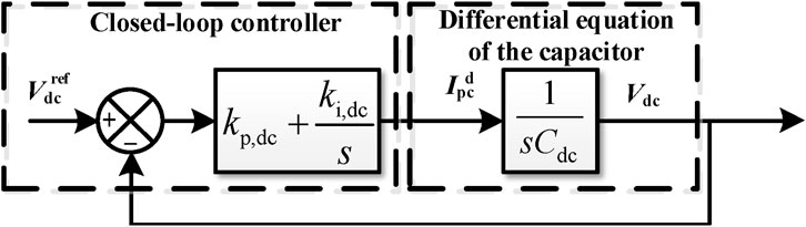
FIGURE 2. Control block diagram of the DC bus voltage system.
The load current can be decomposed into three parts as follows:
where IL,d represents the active component of the load current, IL,q represents the reactive component of the load current, and IL,h represents the harmonic component of the load current. To achieve compensation for IL,q and IL,h, it is necessary to first extract IL,q and IL,h and then control the parallel output port to output currents in the opposite direction of IL,q and IL,h, which can be implemented by the current closed-loop controller. According to Kirchhoff’s current law and Eq. (3), the grid current will no longer contain any reactive or harmonic components. Based on this idea, the control strategy proposed in this paper is given as follows: first, we obtain the reference value of the effective active current that is required to maintain the stability of the DC bus voltage based on the control loop of the DC bus voltage; then, it is multiplied by 1/K of the collected real-time grid voltage to generate the active current output reference using the parallel compensator, denoted as Idref, where K generally takes the rated grid voltage amplitude. Therefore, the reference current of the parallel compensator’s output, denoted as Ipcref, is given as
Since the active current reference for the DC bus voltage loop has been given, the active current reference for the parallel port output Ipcref, obtained from Eq. (4), represents the opposite current of the load reactive current IL,q and the load harmonic current IL,h. Then, the output current Ipc of the parallel port is controlled in real time using a current closed-loop controller. The current controller adopts a proportional resonant (PR) controller, which is denoted as Gcur,p. Therefore, the expression for the drive signal of the parallel inverter is given as
where kp,cur,p represents the proportional coefficient of the PR controller, kr,h,cur,p represents the resonance coefficient for each frequency h, ωcut is the resonant bandwidth control parameter, and ω0 is the natural angular frequency. The detailed control strategy for the parallel compensator is shown in Figure 3. It can be seen from the figure that the grid-connected control uses the instantaneous value of Vg instead of the real-time phase angle of Vg.
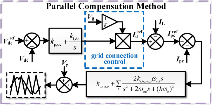
FIGURE 3. The proposed parallel compensation control strategy.
The circuit structure of the parallel port and the overall control block diagram are shown in Figure 1, where Lp1, Lp2, and Cp constitute the interface filters of the parallel inverter. Therefore, the expression for the output current Iout,p of the parallel inverter with respect to the inverter drive signal dp is given by the following:
where Gi,dc represents the transfer function of the inverter drive signal dp to Iout,p, and its expression is given as follows:
Based on the control block diagram and the topology of the single-phase three-leg UPQC, the closed-loop transfer function Φp of the parallel port output current Ipc, with respect to the output current reference Ipcref, can be obtained as follows:
where KPWM is the gain of PWM modulation, which represents the proportional coefficient between the controller output variable and the converter output voltage. From Eqs (6–8), the Bode plot of this closed-loop transfer function is obtained, as shown in Figure 4 and the parameters for plotting the Bode plot can be found in Table 1. From this graph, it can be observed that at odd harmonics frequencies, the magnitude response is 0 dB and the phase response is 0°. This indicates that the amplitude of the parallel port output current Ipc is equal to the amplitude of the output current reference Ipcref, and the phase of the parallel port output current Ipc is equal to the phase of the output current reference Ipcref, i.e., Ipc = Ipcref. Then, the control requirements can be satisfied.
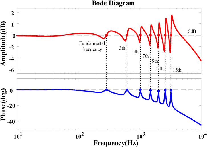
FIGURE 4. Closed-loop Bode plot of the parallel controller.
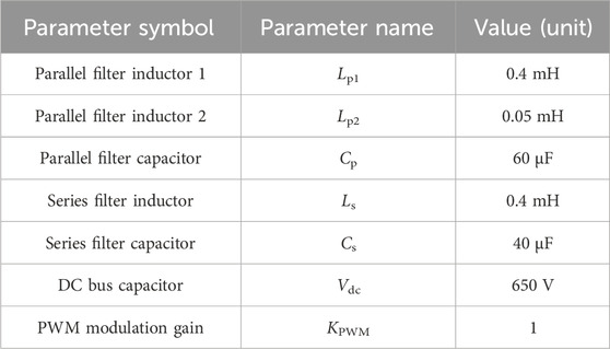
TABLE 1. Table of the relevant parameters for plotting the Bode plot of the control system.
2.3 Series compensation control method
The series compensation port has two control objectives. First, when the grid voltage exceeds the limits, it provides compensating voltage on the line to maintain the load voltage at the rated value. Second, it aims to reduce the harmonic components in the compensated grid voltage and increase the sinusoidal quality of the load voltage. To achieve these objectives, similar to the parallel compensation strategy, a PR controller is selected as the control function for the voltage loop and the current loop. The specific control block diagram is shown in Figure 5. The d-axis voltage Vd and the q-axis voltage Vq can be obtained through a second-order generalized integrator (SOGI), where the transfer functions of Vd and Vq relative to Vg are, respectively, as follows:
where kSOGI is the filter gain coefficient. It is evident from Eqs (9, 10) that when the frequency of Vg is ω0, the amplitude gains of D(s) and Q(s) are both 1 and the phase angle gains are 0 and −90°, respectively. As a result, the grid voltage amplitude Vgamp is as follows:
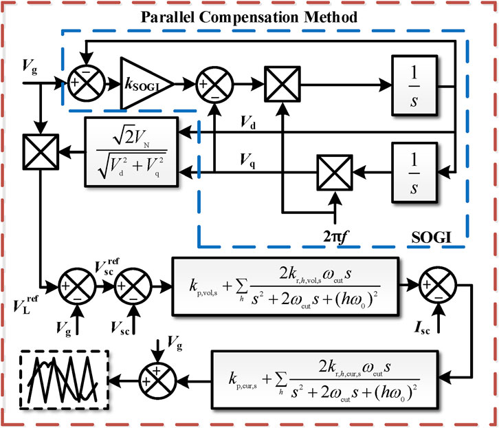
FIGURE 5. The proposed series compensation strategy.
We compare Vgamp from Eq. (11) with the rated grid voltage amplitude and perform some simple calculations, as shown in Figure 7, to obtain the load voltage reference, which has an effective value of VN and the same phase as the grid voltage.
The circuit structure of the series port and the control block diagram of the overall system are shown in Figure 1, where Ls and Cs constitute the interface filter of the series inverter. The expression for the compensation voltage Vsc in terms of the inverter drive signal ds is given by the following:
where Gv,dc represents the gain of the inverter drive signal ds with respect to the output voltage Vsc, and its expression is shown as follows:
Similar to the parallel port, ds is determined by the control system. Based on the control block diagram, as shown in Figure 5, the expression for ds can be obtained by the following:
where Gvol,s represents the transfer function of the voltage controller and Gcur,s represents the transfer function of the current controller, both of which are PR controllers. Moreover, kp,vol,s and kr,h,vol,s are the proportional coefficient and the resonance coefficient of the voltage controller for the series compensator, respectively; kp,cur,s and kr,h,cur,s are the proportional coefficient and the resonance coefficient of the current controller for the series compensator, respectively. Gv,i represents the transfer function of the load current to the output voltage of the series inverter, and its expression is shown as follows:
Therefore, the closed-loop transfer function Φs of the series port output voltage Vsc with respect to the output voltage reference Vscref can be obtained as follows:
From Eq. (12–16), the Bode plot of the closed-loop transfer function Φs is obtained, as shown in Figure 6. The parameters for plotting the Bode plot can be found in Table 1. From the graph, it can be observed that at odd harmonic frequencies, the magnitude response is 0 dB and the phase response is 0°. This indicates that the amplitude of the series port output voltage Vsc is equal to the amplitude of the output voltage reference Vscref, and the phase of the series port output voltage Vsc is equal to the phase of the output voltage reference Vscref, i.e., Vsc = Vscref. Then, the control requirements can be satisfied.
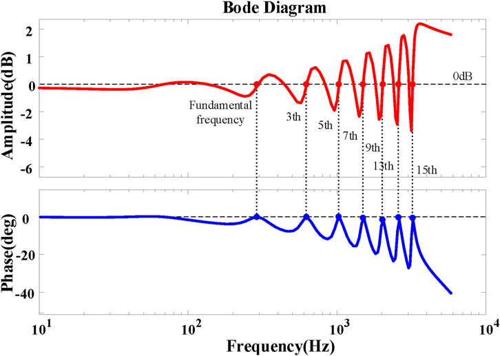
FIGURE 6. Closed-loop Bode plot of the series controller.
3 Experiment results
To verify the effectiveness of the proposed method, the experimental prototype of a single-phase three-leg UPQC is built, as shown in Figure 7. The parameters of the experimental prototype are the same as those given in Table 1. Some controller parameters are shown in Table 2. In addition, the switching frequency is 10 kHz, and the DC bus capacitance value is 2500 μF.
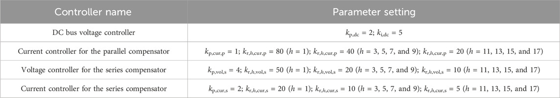
TABLE 2. Some key parameters of the experiment.
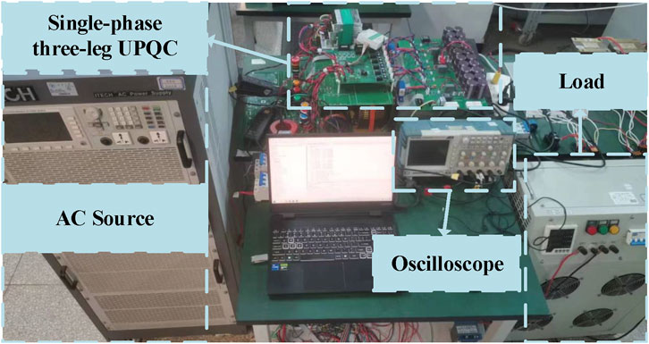
FIGURE 7. Experimental platform.
The first validation was carried out for the effectiveness of series port voltage regulation. The results of the first set of experiments are shown in Figure 8. The grid voltage suddenly dropped from 1.0 p. u. to 0.8 p. u. From the experimental results, it can be seen that there is a slight fluctuation in the DC bus voltage because of the direct utilization of the grid voltage in the proposed method. However, the compensated load voltage remains at 1.0 p. u., and from the detailed waveform, it can be seen that the compensated load voltage has almost no step change, meeting the expected effect.
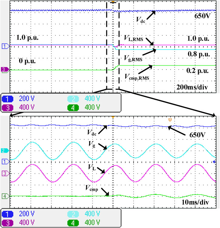
FIGURE 8. Voltage fluctuation compensation experiment.
Moreover, the effectiveness of the parallel port current compensation was verified, as shown in Figure 9. The load is a power electronic non-linear rectifier. Before compensation, the THD of the grid current is 25.67%. After compensation, the THD of the grid current is 3.66%. It can be seen that after compensation, the grid current has almost no harmonic distortion, which means that the experimental results meet the expectations.
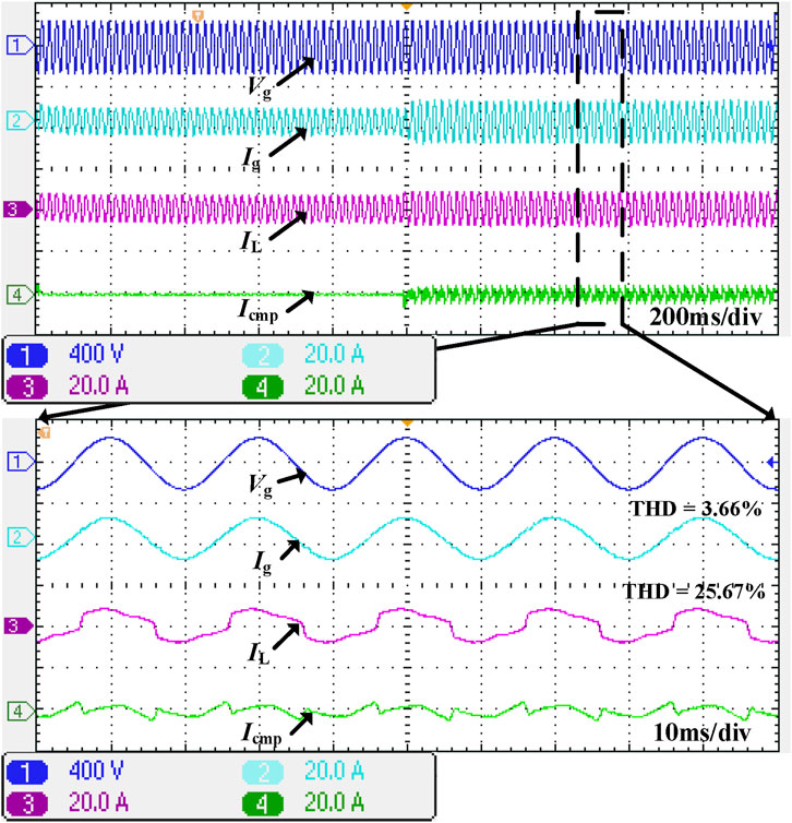
FIGURE 9. Parallel port compensation effect.
In addition, the comparison between the traditional control method and the proposed method can be seen in Figure 10. The load of this experiment is the same as that of experiment 2. The THD of the grid current is 25.67% without any compensation. However, whether the proposed method or the traditional method is applied, the THD of the grid current is significantly improved, where the proposed method can improve to 3.66% and the traditional method can improve to 3.78%. There is no difference in this fact. However, compared to the complexity of the algorithm, the method proposed in this article is greatly simplified.

FIGURE 10. Comparison of the effects between the proposed method and the traditional method.
4 Conclusion
This article presents a control method without a phase-locked loop for the single-phase three-leg UPQC. The instantaneous value of the grid voltage is used for grid connection, which greatly simplifies the complexity of the control algorithm. Furthermore, a simple compensation method is proposed for reactive power current and harmonic current at the grid connection point, which eliminates the need for extracting reactive power current and harmonic current. As a result, it further simplifies the computational complexity of the control. Finally, the experimental results show that the proposed method can achieve series voltage compensation along with reactive power current and harmonic current compensation at the grid connection point. The control method, without the phase-locked loop, proposed in this article is applied for the single-phase UPQC. As for the control method without the phase-locked loop for the three-phase UPQC, it will be further studied in the follow-up work.
Data availability statement
The data analyzed in this study are subject to the following licenses/restrictions: the datasets in this article are the voltage and current values obtained during the experiment. We recorded them using an oscilloscope. The resulting voltage and current waveforms are displayed in the manuscript. Requests to access these datasets should be directed to Weiqi Meng, d2VpcWlfbWVuZ0B0anUuZWR1LmNu.
Author contributions
DF: funding acquisition, investigation, project administration, and writing–original draft. TC: resources, software, validation, and writing–original draft. LZ: formal analysis, supervision, and writing–original draft. WM: writing–review and editing. JH: conceptualization, project administration, and writing–review and editing.
Funding
The authors declare that financial support was received for the research, authorship, and/or publication of this article. This research was funded by State Grid Shandong Electric Power Company.
Conflict of interest
Authors DF and TC were employed by Linyi Power Supply Company of State Grid Shandong Electric Power Company.Author LZ was employed by Yinan Power Supply Company of State Grid Shandong Electric Power Company.
The remaining authors declare that the research was conducted in the absence of any commercial or financial relationships that could be construed as a potential conflict of interest.
Publisher’s note
All claims expressed in this article are solely those of the authors and do not necessarily represent those of their affiliated organizations, or those of the publisher, the editors, and the reviewers. Any product that may be evaluated in this article, or claim that may be made by its manufacturer, is not guaranteed or endorsed by the publisher.
References
Abdalaal, R., and Ho, C. (2021). Analysis and validations of modularized distributed TL-UPQC systems with supervisory remote management system. IEEE Trans. Smart Grid 12 (3), 2638–2651. doi:10.1109/TSG.2020.3044992
Cheng, P. T., and Lee, T. L. (2006). Distributed active filter systems (DAFSs): a new approach to power system harmonics. IEEE Trans. Ind. Appl. 42 (5), 1301–1309. doi:10.1109/TIA.2006.880856
He, J., Du, L., Yuan, S., Zhang, C., and Wang, C. (2019). Supply voltage and grid current harmonics compensation using multi-port interfacing converter integrated into two-AC-bus grid. IEEE Trans. Smart Grid 10 (3), 3057–3070. doi:10.1109/TSG.2018.2817491
He, J., Li, Y. W., and Blaabjerg, F. (2015). An enhanced islanding microgrid reactive power, imbalance power, and harmonic power sharing scheme. IEEE Trans. Power Electron. 30 (6), 3389–3401. doi:10.1109/TPEL.2014.2332998
He, J., Liu, X., Lei, M., and Wang, C. (2020). A broad frequency range harmonic reduction for cascaded-power-cell-based islanded microgrid with lumped PCC filter. IEEE Trans. Power Electron. 35 (9), 9251–9266. doi:10.1109/TPEL.2020.2970462
Lakshmi, S., and Ganguly, S. (2019). An on-line operational optimization approach for open unified power quality conditioner for energy loss minimization of distribution networks. IEEE Trans. Power Syst. 34 (6), 4784–4795. doi:10.1109/TPWRS.2019.2919786
Lu, Y., Xiao, G., Wang, X., Blaabjerg, F., and Lu, D. (2016). Control strategy for single-phase transformerless three-leg unified power quality conditioner based on space vector modulation. IEEE Trans. Power Electron. 31 (4), 2840–2849. doi:10.1109/TPEL.2015.2449781
Mishra, M. K., and Lal, V. N. (2022). An enhanced control strategy to mitigate grid current harmonics and power ripples of grid-tied PV system without PLL under distorted grid voltages. IEEE J. Emerg. Sel. Top. Power Electron. 10 (4), 4587–4602. doi:10.1109/JESTPE.2021.3107869
Moeini, A., Zhao, H., and Wang, S. (2018). A current-reference-based selective harmonic current mitigation PWM technique to improve the performance of cascaded H-bridge multilevel active rectifiers. IEEE Trans. Ind. Electron. 65 (1), 727–737. doi:10.1109/TIE.2016.2630664
Mohammed, N., Ravanji, M. H., Zhou, W., and Bahrani, B. (2023). Enhanced frequency control for power-synchronized PLL-less grid-following inverters. IEEE Open J. Industrial Electron. Soc. 4, 189–204. doi:10.1109/OJIES.2023.3285010
Silva, S., Campanhol, L., Pelz, G., and Souza, V. (2020). Comparative performance Analysis involving a three-phase UPQC operating with conventional and dual/inverted power-line conditioning strategies. IEEE Trans. Power Electron. 35 (11), 11652–11665. doi:10.1109/TPEL.2020.2985322
Srinivas, V., Singh, B., and Mishra, S. (2019). Fault ride-through strategy for two-stage grid-connected photovoltaic system enabling load compensation capabilities. IEEE Trans. Ind. Electron. 66 (11), 8913–8924. doi:10.1109/TIE.2019.2899546
Sun, X., Zeng, J., and Chen, Z. (2013). Site selection strategy of single-frequency tuned R-APF for background harmonic voltage damping in power systems. IEEE Trans. Power Electron. 28 (1), 135–143. doi:10.1109/TPEL.2011.2179121
Wang, S., and Yang, J. (2023). Active disturbance rejection control of three-phase LCL power conversion system under non-ideal grid conditions. Front. Energy Res. 11. doi:10.3389/fenrg.2023.1170058
Xia, Y., Feng, Z., Chen, R., Wu, J., and Huang, Q. (2022). A harmonic suppression strategy for grid-connected inverters based on quadrature sinewave extractor. Front. Energy Res. 10. doi:10.3389/fenrg.2022.1020676
Zhang, F., Wang, Y., Huang, D., Lu, N., Jiang, M., Wang, Q., et al. (2022a). Integrated energy system region model with renewable energy and optimal control method. Front. Energy Res. 10. doi:10.3389/fenrg.2022.1067202
Keywords: unified power quality conditioner, phase-locked loop, voltage fluctuation, harmonic control, power quality
Citation: Feng D, Chen T, Zhang L, Meng W and He J (2024) A control method for the single-phase three-leg unified power quality conditioner without a phase-locked loop. Front. Energy Res. 12:1343520. doi: 10.3389/fenrg.2024.1343520
Received: 23 November 2023; Accepted: 05 January 2024;
Published: 24 January 2024.
Edited by:
Youbo Liu, Sichuan University, ChinaReviewed by:
Xiaokang Liu, Polytechnic University of Milan, ItalyAndrea Toscani, University of Parma, Italy
Copyright © 2024 Feng, Chen, Zhang, Meng and He. This is an open-access article distributed under the terms of the Creative Commons Attribution License (CC BY). The use, distribution or reproduction in other forums is permitted, provided the original author(s) and the copyright owner(s) are credited and that the original publication in this journal is cited, in accordance with accepted academic practice. No use, distribution or reproduction is permitted which does not comply with these terms.
*Correspondence: Jinwei He, amlud2VpLmhlQHRqdS5lZHUuY24=