 Ximei Zhan1
 Jinfeng Wang
 Aihong Tang
 Qian Wang
94% of researchers rate our articles as excellent or good
Learn more about the work of our research integrity team to safeguard the quality of each article we publish.
Find out more
ORIGINAL RESEARCH article
Front. Energy Res. , 22 February 2024
Sec. Smart Grids
Volume 12 - 2024 | https://doi.org/10.3389/fenrg.2024.1342008
In order to solve the problem of the power quality caused by distributed power access to the distribution network, this paper proposes a coordinated control strategy of reactive power compensation based on a flexible distribution transformer. First, the working principle of the flexible distribution transformer is analyzed, and the mathematical model of energy acquisition and the regulation converter of the flexible distribution transformer are studied as well. The device-level control strategies of energy acquisition and regulation converters are proposed, respectively. Then, in order to maintain the stability of the bus voltage and quickly respond to the reactive power changes of the system, a coordinated control strategy for the reactive power compensation of flexible distribution transformers is proposed. The priority herein is to maximize the reactive power compensation capacity of the energy harvesting converter. When the energy harvesting converter reaches the compensation upper limit, the control converter is used for reactive power compensation to further suppress the grid voltage fluctuation. Finally, it is verified through simulations that the flexible distribution transformer can realize the reactive power compensation of the distribution network and effectively improve the power quality of the distribution network.
In order to achieve the goal of “carbon peak and carbon neutrality,” the distributed new energy led by wind power and photovoltaics is developing rapidly. Distributed photovoltaics are connected to the distribution network nearby. The random fluctuation of the distributed photovoltaic output and the time–space mismatch of the “source and load” cause power quality problems, such as power flow reversal (Tang et al., 2022a; Tang et al., 2023; Tang et al., 2022a; Tang et al., 2022b), voltage fluctuation, and harmonic distortion in the distribution network, and even reduce the stability and reliability of the distribution system in serious cases. Traditional distribution transformers use mechanical switches for voltage regulation, do not have continuous voltage regulation capabilities, and can only regulate the voltage at the point where the transformer is located. The voltage in other areas is further reduced due to the lack of reactive power, which cannot meet the operation requirements of the new distribution system. Power electronic transformers can not only complete the functions of voltage-level conversion, electrical isolation, and energy transfer but also realize the regulation of the power flow. However, power electronic transformers use a large number of power electronic devices, which have the disadvantages of a large loss, low capacity, and high cost. Therefore, traditional transformers and power electronic transformers cannot adapt to the operation requirements of new distribution systems (Tang et al., 2022a; Tang et al., 2023; Tang et al., 2022c; Tang et al., 2022b).
The hybrid transformer based on the combination of the traditional transformer and power electronic equipment not only has the basic functions of the traditional power transformer but also has the functions of improving the power quality, reactive power compensation, and power flow control. Cai et al. (2021) improved the single-phase dq0 transformation method, constructed the virtual three-phase voltage, and used the derivative method to replace the low-pass filter, which avoided detection delay and improved the real-time accuracy of the input and the removal of the load voltage compensation circuit of the hybrid distribution transformer. Aiming at the new hybrid distribution transformer, the DC bus voltage control of the flexible distribution transformer based on fuzzy control, combined with PI control, is proposed in Li et al. (2021), which effectively improves the transient performance of the DC bus voltage control system. Lee et al. (2022) proposed a hybrid distribution transformer topology in which the two taps of the converter and the transformer are connected in series so that the transformer has the ability to maintain the load voltage stability, compensate grid voltage harmonics, and improve the grid power factor. Li et al. (2023) proposed a hybrid power transformer topology based on a single-phase converter. The series converter is used to dynamically adjust the voltage of the distribution network, and the parallel converter is used to adjust the power quality. The proposed topology is simple and realizes dynamic voltage regulation. As a new type of distribution transformer, the flexible distribution transformer has been proposed for a re-topology and control strategy on the related research side. However, the application of the flexible distribution transformer in the reactive power compensation of the distribution system is relatively less.
Aiming at the problem of voltage fluctuation and reactive power shortage in the distribution network, the traditional reactive power compensation method is mainly used to install compensation equipment. In Pan et al. (2019), a partition automatic voltage-control strategy for the active distribution network considering the reactive power output of the microgrid is proposed, which reasonably dispatches the coordinated operation of the microgrid and traditional reactive power-compensation equipment and carries out reactive power compensation for the active distribution network so as to realize flexible and fast automatic voltage control in the control area and improve the voltage quality of the active distribution network. However, there are no specific indicators to evaluate the voltage support capability of the proposed method. In Zhao et al. (2017), two unbalanced states of cascaded H-bridge photovoltaic grid-connected inverters are analyzed, and a centralized control strategy of reactive power compensation based on the proportional distribution of active power and the reactive power distribution according to the demand is proposed to ensure the stable operation of inverters when the power is seriously unbalanced. However, the adjustment range of the control policy mentioned previously is limited. In Le et al. (2020), considering the reactive power compensation equipment connected to the distribution network, the multi-objective distributed optimal control of the distribution network, including node voltage control, active power exchange, and reactive power exchange control, is realized by grouping the distributed power supply and reactive power compensation equipment. However, the algorithm should be further improved for different control objectives and system requirements. He et al. (2022) considered using the reactive power regulation ability of the inverter to compensate for the reactive power of the photovoltaic access node, according to the set reactive power control strategy, and also ensured that the voltage did not exceed the upper limit. However, the failure of photovoltaics to operate at the maximum power point will reduce the system economy. Sun et al. (2023) proposed the use of an energy storage type distribution network static synchronous compensator to realize the comprehensive compensation of the voltage fluctuation, voltage over-limit, and three-phase unbalance of the distribution network. In Mohammed and Ciobotaru (2023), this paper proposed a droop control strategy for grid-connected inverters with adaptive power to solve the problems of the voltage fluctuation of public AC buses caused by a new energy grid connection, non-optimal power factor of power transmission from inverters to the public AC bus, and transmission loss. The method given in Sun et al. (2023) and Mohammed and Ciobotaru (2023) is easily affected by the external parameters and disturbances of the system, which leads to the performance degradation of the proposed method. ZeraatiGolshanGuerrero (2019) proposed the connection of the photovoltaic inverter in a triangle and a star pattern to compensate for the negative sequence and the zero sequence components of the voltage, respectively, and to control the voltage within the allowable range. The distributed algorithm based on the consensus increases the computational complexity. In YOU and GUO (2022), a new integrated converter with a four-leg converter topology and integrated fault suppression and reactive power compensation functions is proposed, which gives a set of converters the functions of single-phase ground fault suppression and reactive power compensation at the same time, improves the utilization rate of equipment, and reduces the cost of equipment. Liang et al. (2023) proposed an active power control strategy for the reactive power compensation of the battery energy-storage quasi-Z-source inverter photovoltaic power generation system based on the virtual synchronous generator technology and realized photovoltaic power generation and reactive power compensation at the same time. The control strategy and parameter design, as shown in YOU and GUO (2022) and Liang et al. (2023), are complex, and the real-time performance is poor. The above reactive power compensation method provides reactive power support by improving the corresponding control strategy of the grid-connected converter. However, the distribution network has a wide range of points and various load types, and the grid-connected converter alone is not enough to maintain the reactive power balance of the system.
The contribution of this paper is twofold. First, a flexible distribution transformer topology based on the combination of a traditional transformer and power electronic equipment is proposed. The electromagnetic power transformer mainly undertakes power transmission. The energy converter maintains the stability of the DC capacitor voltage and regulates the output of the converter to control the compensation voltage. Therefore, the flexible distribution transformer not only has the basic functions of a traditional power transformer but also has the function of reactive power compensation to improve the power quality. The dq feedforward decoupling control strategy is used to realize the decoupling control and the error-free control of the output current of the energy converter and the output voltage of the regulating converter. At the same time, the linear relationship between the reactive power output of flexible distribution transformer winding and the output voltage of the regulating converter and the output current of the energy converter is deduced. The control strategy is designed to correctly calculate the command value of the output voltage of the regulating converter and the output current of the energy converter so as to realize the reactive power compensation function of the hybrid power transformer.
The rest of the structure of this paper is as follows: the second section introduces the topology of the flexible distribution transformer and the working principle of reactive power compensation. The third section discusses the mathematics and loss model of the flexible distribution transformer converter. In the fourth section, the control strategy of the converter reactive power compensation is proposed. The fifth section gives the simulation results to verify the feasibility of the proposed flexible distribution transformer reactive power compensation control strategy. Finally, the sixth section draws a conclusion.
The topology of the flexible distribution transformer, studied in this paper, is shown in Figure 1. It can be divided into three components: the electromagnetic power transformer, energy converter, and control converter. The electromagnetic power transformer is the main part of the flexible distribution transformer. The main structure is a double-winding power-frequency transformer. The main function is to bear most of the power transmission and transform the voltage level of the primary side winding bus and the secondary side winding bus. The converter is connected in parallel to the secondary winding of the electromagnetic power transformer. Its structure is an AC/DC three-phase bridge-voltage source converter, which is mainly used to maintain the stability of the common DC capacitor voltage and which independently compensates for the reactive power to the system. The control converter is connected in series on the primary side winding of the power transformer. Its structure comprises three independent AC/DC single-phase full-bridge converters. The main function of it was to adjust the output voltage, according to the control target of the flexible distribution transformer. It is the main control equipment of the flexible distribution transformer. The energy harvesting converter and the control converter are connected and exchanged active power through the coupled common DC capacitor. Under normal operating conditions, the protection action switch takes the A phase as an example,
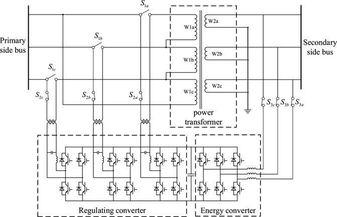
FIGURE 1. Topology structure diagram of the flexible distribution transformer.
When analyzing the working principle of the flexible distribution transformer, the specific situation of the power electronic switch inside the converter can be ignored. At the same time, when the loss is not considered, the converter can be equivalent to an ideal controlled-voltage source or current source, thereby simplifying the analysis process. The main function of the converter is the inverter compensation voltage, so it can be equivalent to an ideal, controlled-voltage source. The main function of the converter was to stabilize the DC-side voltage, and its control target is usually the current injected into the energy extraction winding of the transformer, so it can be equivalent to an ideal controlled current source. In order to further simplify the equivalent circuit of the flexible distribution transformer, the power transformer in the flexible distribution transformer is regarded as an ideal transformer. Based on the topology of Figure 1, the simplified single-phase equivalent circuit is shown in Figure 2.

FIGURE 2. Simplified circuit diagram of the flexible distribution transformer.
Figure 2 shows that Uin represents the voltage on the actual primary side bus of the flexible distribution transformer, U1 represents the voltage on the primary side winding of the power transformer in the flexible distribution transformer, U2 represents the voltage on the secondary side winding of the power transformer, Ush represents the voltage on the energy winding side of the flexible distribution transformer, k represents the voltage ratio between the primary and secondary side windings of the power transformer, I1 represents the current flowing through the primary side winding of the power transformer, I2 represents the current flowing through the secondary side winding of the power transformer, and Use represents the output voltage of the control converter. Ish represents the output current of the energy converter; Z1 and Z2 represent the line impedance; Us and Zs represent the system power supply voltage and system impedance, respectively; and
First of all, for the electrical quantities of the power transformer part, according to the law of electromagnetic induction and the law of flux conservation, we obtain the following relationships:
In order to facilitate the analysis of the relationship between the electrical quantities in the flexible distribution transformer, taking the phasor
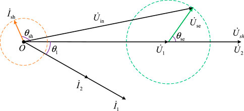
FIGURE 3. Phasor diagram of the flexible distribution transformer.
When the flexible distribution transformer is not equipped with an energy storage device, it cannot exchange active power with the power system for a long time. Therefore, the flexible distribution transformer needs to balance the active power of the converter and the energy converter. The active power absorbed by the converter from the power system is shown in Figure 3:
The active power absorbed by the converter from the power system is as follows:
When the flexible distribution transformer is running, the output voltage of the converter and the output current of the energy converter need to meet the constraints; they are expressed as follows:
Equation 4 is the basic condition for the stable operation of the flexible distribution transformer. On this basis, the flexible distribution transformer can change the output of the control converter and the energy converter to achieve the purpose of reactive power compensation. The following will briefly introduce the basic working principle of the above described functions.
Based on the structure of the voltage source converter, the control converter and the energy converter of the flexible distribution transformer have independent reactive power compensation capabilities, which can inject the required reactive power into the power system. Figure 3 shows that the reactive power injected into the system by the flexible distribution transformer can be expressed as follows:
Equation 5 shows that the flexible distribution transformer has a certain reactive power compensation ability, but the reactive power compensation ability of the flexible distribution transformer will be constrained by Eq. 4. The flexible distribution transformer will reduce its own additional reactive power compensation ability when performing voltage regulation. The flexible distribution transformer can output the maximum reactive power compensation capacity without voltage regulation:
Setting n as the ratio of the amplitude of the output current
Setting m as the ratio of the amplitude
Substituting Formula (7) and Formula (8) into Formula (6), we obtain the following:
It can be seen from Eq. 9 that the reactive power compensation capability of the flexible distribution transformer depends on the amplitude of the output voltage or output current of the control converter and the energy converter. Therefore, in order to obtain a greater reactive power compensation capability, it is necessary to configure a control converter that can output higher voltage and an energy converter that can output greater current.
The structure of the energy converter in the flexible distribution transformer, studied in this paper, is a three-phase bridge-voltage source converter, and its equivalent circuit structure is shown in Figure 4. In the figure,
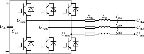
FIGURE 4. Equivalent circuit structure diagram of the energy converter.
Figure 4 shows that the loop equation of the energy converter in the ABC three-phase stationary coordinate system can be obtained as follows:
The variables in (10) are AC quantities, which are not easy to control. Therefore, the Park transformation can be used to convert each AC variable into the DC flow in the synchronous rotating coordinate system so that the output current of the energy converter can be easily controlled. In the coordinate transformation, the voltage
By multiplying the Park transformation matrix, shown in Eq. 11, on both sides of Eq. 10, the loop equation of the energy converter in the dq0 synchronous rotating coordinate system can be obtained as follows:
In (12),
The structure of the control converter in the flexible distribution transformer is represented by three independent single-phase full-bridge voltage source converters, and its basic equivalent circuit structure is shown in Figure 5. In the diagram,
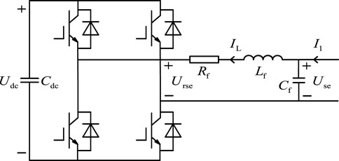
FIGURE 5. Control converter equivalent circuit structure diagram.
Figure 5 shows that the loop equation of the control converter in the ABC three-phase stationary coordinate system can be obtained as follows:
In order to convert the AC variables in Eq. 13 into the direct flow in the synchronous rotating coordinate system, it is necessary to construct new variables with a lag of 90° to realize the single-phase Park transformation. These new variables with a lag of 90° also satisfy the mathematical relationship of Eq. 14, so they are expressed as follows:
In Formula (14) and Formula (15),
In the coordinate transformation, the line current
By multiplying the Park transformation matrix, shown in Eq. 16, on both sides of Eq 14 and Eq 15, the loop equation of the control converter in the dq0 synchronous rotating coordinate system can be obtained as follows:
The energy converter and the control converter in the flexible distribution transformer contain multiple sub-modules composed of an IGBT (insulated-gate bipolar transistor) and a freewheeling diode. The loss of a single sub-module includes the IGBT, freewheeling diode conduction, and turn-off losses.
The on-state loss
In the formula,
The on-state loss of the freewheeling diode, anti-parallel to the IGBT, is given as follows:
In the formula,
IGBT switching losses include turn-on and turn-off losses. The energy loss of the IGBT turn-on and turn-off once is
In the formula,
The losses of the IGBT and anti-parallel freewheeling diode are as follows:
In the aforementioned formula,
The analysis above is aimed at the power loss of a single IGBT and its anti-parallel freewheeling diode. The total loss of the energy converter can be approximately 12 times that of the IGBT and the freewheeling diode, and the total power loss of the regulated converter can be approximately six times that of the IGBT and the freewheeling diode.
The total power loss of the converter is given as follows:
The total power loss of the control converter is given as follows:
The loss of the power transformer is mainly composed of the no-load loss and the load loss. The calculation formulas of the no-load loss and the load loss are given as follows:
In the formula,
Based on the above analysis, the total loss after the flexible distribution transformer is put into operation, which is given as follows:
The control converter and the energy converter in the flexible distribution transformer are based on the structure of the voltage source converter. Therefore, the flexible distribution transformer naturally has the function of reactive power compensation, and the reactive power output of the control converter and the energy converter is independent of each other; the reactive power injected into the system can be controlled independently. The expression of the reactive power
The expression of the reactive power
It can be known from Eq. 20 that the reactive power injected into the power system by the flexible distribution transformer is affected by the q-axis component of the output voltage of the converter and the q-axis component of the output current of the energy converter. Therefore, the control of the q-axis component of the output voltage of the converter and the q-axis component of the output current of the energy converter can control the reactive power injected into the power system by the flexible distribution transformer.
The instruction value of the reactive power that needs to be injected into the power system by the flexible distribution transformer is
The upper and lower limits of the reactive power output capacity of the energy converter are
When
The upper and lower limits of the reactive power output capacity of the control converter are
When
In order to realize the error-free control of reactive power compensation, a PI controller can be added to the command value expression of the q-axis component of the output voltage of the converter and the q-axis component of the output current of the energy converter in Formula (19)∼Formula (25). Therefore, the control strategies for the q-axis component of the output current of the energy converter are given as follows:
In the formula,
The control strategies for regulating the q-axis component of the output voltage of the converter are given as follows:
In the formula,
Formulas 34, 35 are the modified reactive power compensation control strategies of flexible distribution transformers. Based on Formulas 34, 35, the control block diagram of the reactive power compensation control strategy of the flexible distribution transformer is built, as shown in Figure 6.
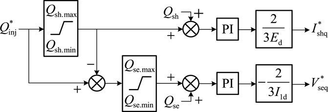
FIGURE 6. Flexible distribution transformer reactive power compensation-control strategy block diagram.
After determining the command value
This section will simulate and verify the effectiveness of the reactive power compensation control strategy of the flexible distribution transformer. In Intel Core i7-7700, the main frequency is 2.80 GHz, with a memory of 16-GB host computing power. In this section, a test system with flexible distribution transformers is built based on PSCAD/EMTDC, as shown in Figure 7.
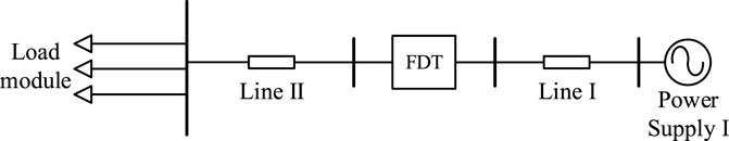
FIGURE 7. Test system for the steady-state control of the flexible distribution transformer.
For the three-phase bridge converter with the L-filter, the capacity of injecting inductive reactive power into the power system is smaller than that of the capacitive reactive power. At the same time, the capacity of injecting the inductive reactive power into the power system using a single-phase bridge converter in a series is different from that of the capacitive reactive power. In this section, the smaller capacity of the inductive reactive power and the capacitive reactive power is set as the upper and lower limits of the capacity of the energy converter and the control converter, respectively. Therefore, based on the parameters of the flexible distribution transformer in Table 1, the upper and lower limits of the capacity of the reactive power compensation of the energy converter are set as ±80 kVar. The upper and lower limits of the reactive power compensation capacity of the converter are ±30 kVar.
A. Verification of the reactive power compensation performance of the flexible distribution transformer
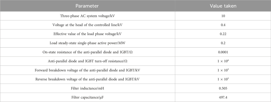
TABLE 1. Main parameter settings of the AC grid simulation model.
The process of the simulation test is set as follows: the test system is the initialization process before 0.1-s time, the flexible distribution transformer is put into operation at 0.1-s time, the DC capacitor is charged at 0.2-s time, and the output current q-axis component of the energy converter is controlled to be zero. The reactive power injected into the system by the flexible distribution transformer is adjusted at 1.0-s time. The command value of the injected reactive power is set to 100 kVar at 1-s time, which jumps to 60 kVar at 2-s time, to 40 kVar at 3-s time, and to 100 kVar at 4-s time.
The waveforms of the reactive power injected into the power system by the energy converter and the reactive power injected into the power system by the control converter are shown in Figure 8.
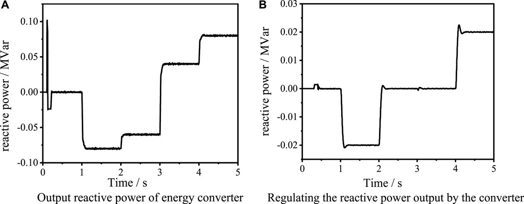
FIGURE 8. Waveform diagram of the output reactive power of the flexible distribution transformer.
It can be seen from Figure 8 that the reactive power injected into the power system by the energy converter has a large fluctuation but a short duration due to the uncontrolled rectification at 0.1-s time. At 1.0 s, due to the instruction of reactive power compensation, the reactive power output by the energy converter begins to adjust and stabilize at 80 kVar, and the reactive power output by the converter is regulated to 20 kVar; at the time of 2 s, due to the adjustment of the reactive power compensation command value, the reactive power output of the energy converter is adjusted to 60 kVar, and the reactive power output of the control converter is adjusted to 0 kVar; at the time of 3 s, the output reactive power is adjusted to 40 kVar, and the output reactive power of the energy converter is adjusted to 40 kVar. The reactive power injected by the converter to the power system is maintained at zero. The reactive power output at 4 s is adjusted to 100 kVar, and the reactive power output by the energy converter begins to adjust and stabilize at 80 kVar; the reactive power injected by the converter into the power system is adjusted to 20 kVar.
As can be seen from Figure 9, when the flexible distribution transformer is used in the operation at 0.1 s, the DC capacitor voltage quickly reaches the voltage value of uncontrolled rectification of 0.8 kV. After charging the DC capacitor at 0.2 s, the DC capacitor voltage can quickly reach the rated value of 1 kV and remain stable.
B. Verification of the voltage regulation characteristics of the flexible distribution transformer
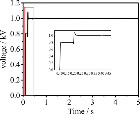
FIGURE 9. DC capacitor voltage of the flexible distribution transformer.
When the simulation system runs for 0.6 s, the voltage sag of the power side system is set. The traditional transformer does not actively change the tap adjustment voltage after the system voltage sag. By changing the tap adjustment voltage of the transformer, the aim is to change the reactive power distribution of the system so that the system voltage is adjusted. As shown in Figure 10, when the system voltage sags to 0.871 pu, the traditional transformer cannot actively adjust the voltage, and the low-voltage side voltage of the system is in a state of sag. If there is a shortage of reactive power in the system, the traditional transformer voltage regulation will lead to the reduction of other node voltages and the problem of insufficient reactive power in the system has not been solved.
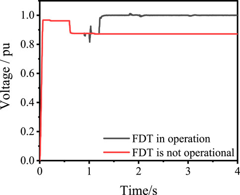
FIGURE 10. Low-voltage side voltage of the flexible distribution transformer.
The system charges the DC capacitor in 0.9 s. In the reactive power compensation coordinated control system of the flexible distribution transformer, it is determined that the stable voltage command value of 1 pu is required to adjust the system voltage to obtain energy and regulate the converter. In 1.2 s, the flexible distribution transformer control system is put to use to maintain the voltage stability, and the corresponding reactive power is obtained to maintain the reactive power balance.
C. Operation efficiency of the flexible distribution transformer
In the simulation system of Figure 11, the efficiency of the flexible distribution transformer is calculated by measuring the active power at both ends of the flexible distribution transformer. The input power of the flexible distribution transformer is 0.635 MW, the output power is 0.627 MW, and the efficiency of the flexible distribution transformer is 98.7 % as shown in Figure 12. The working efficiency of the power electronic transformer is 96% (Li et al., 2020). Compared with the power electronic transformer, the internal loss of the flexible distribution transformer is smaller and the operation efficiency is higher.
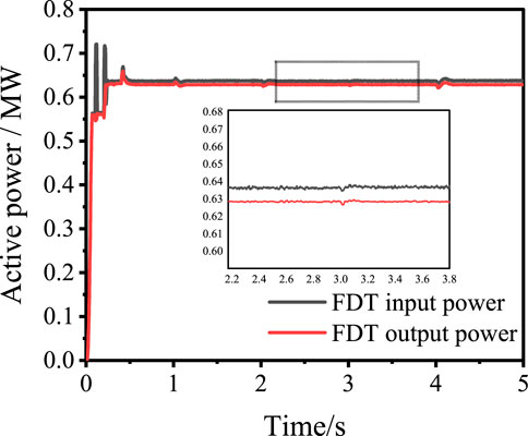
FIGURE 11. Flexible distribution transformer input/output active power.
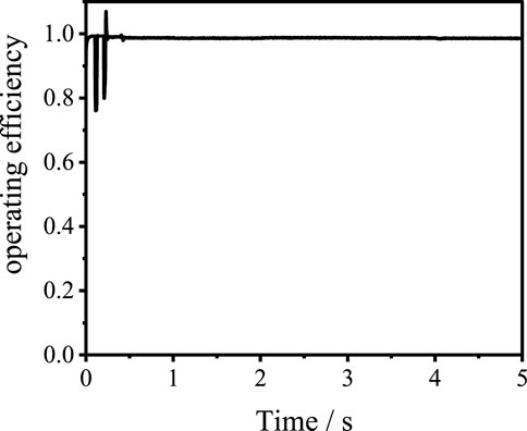
FIGURE 12. Flexible distribution transformer working efficiency.
Through the simulation mentioned above, the reactive power compensation control strategy of the flexible distribution transformer, proposed in this paper, can automatically distribute the reactive power output that the energy converter and the control converter need to bear, following the command value of reactive power. At the same time, it will not exceed the upper and lower limits of the output reactive power capacity of the energy converter and the control converter, respectively. The simulation experiment verifies the effectiveness of the reactive power compensation control strategy of the flexible distribution transformer proposed in this paper. Based on the reactive power compensation control strategy, the flexible distribution transformer can compensate for the reactive power of the power system and can always follow the command value of reactive power to realize the reasonable distribution of the reactive power between the energy converter and the control converter so as to output the capacitive reactive power or the inductive reactive power to meet the reactive power control needs of the power system.
Aiming at the voltage fluctuation and reactive power shortage caused by the distributed new energy grid connection, this paper proposes a coordinated control strategy of reactive power compensation using the flexible distribution transformer. First, the technology of the flexible distribution transformer composed of the traditional transformer and power electronic equipment is introduced. The topology of the flexible distribution transformer with reactive power support capability is proposed. The mathematical model of the energy converter and the control converter in the flexible distribution transformer in the synchronous rotating coordinate system is deduced and established. The decoupling control and error-free control of the output current of the energy converter and the output voltage of the converter are realized using the dq feedforward decoupling control strategy. The reactive power output by the control converter and the energy converter in the flexible distribution transformer is independent of each other, and the reactive power injected into the system by the two is controlled independently. The reactive power compensation method of the flexible distribution transformer proposed in this paper has the following advantages: 1) the flexible distribution transformer can maintain voltage stability according to the set voltage reference value. 2) The reactive power of the system is compensated and the reactive power balance of the system is maintained. Compared with a single converter, the compensation capacity is increased by 37.5%. 3) A high work efficiency to ensure the economic operation of the distribution network. The effectiveness of the reactive power compensation-coordinated control strategy proposed in this paper is verified by simulations.
The original contributions presented in the study are included in the article/Supplementary Material; further inquiries can be directed to the corresponding author.
XZ: conceptualization, formal analysis, and writing–review and editing. JW: conceptualization and writing–review and editing. GG: data curation and writing–review and editing. YY: data curation and writing–review and editing. DG: formal analysis and writing–review and editing. AT: conceptualization, data curation, and writing–review and editing. QW: software, validation, visualization, writing–original draft, and writing–review and editing. WL: software, validation, visualization, and writing–review and editing.
The author(s) declare that financial support was received for the research, authorship, and/or publication of this article. The first author is grateful to the China Southern Power Grid; the work received funding from the “China Southern Power Grid” through the project “Research on New Distributed Power Flow Control and New Flexible Distribution Transformer Technology” (project number: GDKJXM20222475).
The authors of this article are grateful to the China Southern Power Grid Power Grid Project for funding.
Authors XZ and GG were employed by the Foshan Power Supply Bureau of Guangdong Power Grid Co., Ltd. Authors JW and YY were employed by the Electric Power Research Institute of Guangdong Power Grid Co., Ltd. Author DG was employed by the Qingyuan Power Supply Bureau of Guangdong Power Grid Co., Ltd.
The remaining authors declare that the research was conducted in the absence of any commercial or financial relationships that could be construed as a potential conflict of interest.
All claims expressed in this article are solely those of the authors and do not necessarily represent those of their affiliated organizations, or those of the publisher, the editors, and the reviewers. Any product that may be evaluated in this article, or claim that may be made by its manufacturer, is not guaranteed or endorsed by the publisher.
Cai, S., Liang, D., Zhou, K., et al. (2021). Load voltage control switching strategy of hybrid distribution transformer based on improved single-phase dq0 voltage detection. J. Electr. Technol. 36 (S01), 7. doi:10.19595/j.cnki.1000-6753.tces.l90165
He, X., Zhong, C., Liu, X., Zhang, T., and Chen, L. (2022). Voltage control strategy of medium voltage distribution network with distributed photovoltaic power generation. Electr. Meas. Instrum. 59 (05), 142–148. doi:10.19753/j.issn1001-1390.2022.05.019
Le, J., Zhou, Q., Wang, C., and Zhao, L. (2020). Research on optimal control strategy of distribution network with reactive power compensation equipment and distributed power supply. Power Syst. Prot. control 48 (18), 38–47. doi:10.19783/j.cnki.pspc.191273
Lee, H. J., Yoon, S. W., and Yoon, Y. (2022). Hybrid distribution Transformer based on an existing distribution transformer and a Series-Connected Power Converter. IEEE Trans. Power Deliv. 37 (5), 4202–4211. doi:10.1109/TPWRD.2022.3147820
Li, D., Liang, D., and Gao, Y. (2021). etc. A control strategy of hybrid distribution transformer based on fuzzy control. J. Electr. Technol. 36 (S02), 9. doi:10.19595/j.cnki.1000-6753.tces.L90171
Li, K., Wen, W., Zhao, Z., et al. (2020). Design and implementation of four-port Megawatt-level high-frequency-bus based power electronic transformer. IEEE Trans. Power Electron. (99), 1–1. doi:10.1109/TPEL.2020.3036249
Li, W., Qu, Y., Xu, P., et al. (2023). A converter-based hybrid transformer for regulating the voltage of distribution system[C]//2023 IEEE 14th international symposium on power electronics for distributed generation systems. China: PEDG, 99–104. doi:10.1109/PEDG56097.2023.10215211
Liang, W., Liu, Y., and Shen, Y. (2023). Active Power Control integrated with reactive power compensation of battery energy stored Quasi-Z source inverter PV power system operating in VSG mode. IEEE J. Emerg. Sel. Top. Power Electron. 11 (1), 339–350. doi:10.1109/JESTPE.2021.3137397
Mohammed, N., and Ciobotaru, M. (2023). Adaptive power control strategy for smart droop-based grid-connected inverters. IEEE Trans. Smart Grid 13 (3), 2075–2085. doi:10.1109/TSG.2022.3141265
Pan, Li, He, P., and Hu, H. (2019). Considering the partition automatic voltage control strategy of active distribution network with the participation of microgrid. J. Electr. Technol. 34 (21), 4580–4589. doi:10.19595/j.cnki.1000-6753.tces.181653
Sun, Z., Zhang, Y., and Qin, L. (2023). Comprehensive compensation strategy for power quality of energy storage DSTATCOM in distribution network. J. Power Syst. Automation 35 (04), 75–84. doi:10.19635/j.cnki.csu-epsa.001088
Tang, A., Gao, M., Huang, Y., Zhao, H., Xu, Q., and Xu, Z. (2022c). Equivalent model of coordinating energy exchange for series and shunt converters in distributed power flow controller. Automation Electr. Power Syst. doi:10.7500/AEPS20180118002
Tang, A., Xing, S., Shang, Y., Guo, G., Yu, M., and Zhan, X. (2023). Harmonic mitigation method and control strategy of offshore wind power system based on distributed power flow controller. Automation Electr. Power Syst. doi:10.7500/AEPS20230113008
Tang, A., Zhou, W., Song, J., Qiu, P., Qian, C., Zhai, X., et al. (2022a). Optimal output power coordinated control strategy of distributed power flow controller. Int. J. Electr. Power and Energy Syst. 140, 2022, 108075. doi:10.1016/j.ijepes.2022.108075
Tang, Y., Yang, H., Yang, L., et al. (2022b). Research on topology and control method of uninterrupted ice melting device based on non-contact coupling power flow controller. Proc. CSEE. doi:10.13334/j.0258-8013.pcsee.220221
You, J., and Guo, M. (2022). Integrated converter with reactive power compensation and fault suppression functions and its control strategy. Grid Technol. 46 (06), 2241–2248. doi:10.13335/j.1000-3673.pst.2021.1389
Zeraati, M., Golshan, M. E. H, and Guerrero, J. M. (2019). Voltage quality improvement in low voltage distribution networks using reactive power capability of single-phase PV inverters. IEEE Trans. Smart Grid 10 (5), 5057–5065. doi:10.1109/TSG.2018.2874381
Keywords: distribution network, power quality, reactive power shortage, flexible distribution network transformer, coordinated control strategy
Citation: Zhan X, Wang J, Guo G, Yao Y, Gong D, Tang A, Wang Q and Leng W (2024) Coordinated control strategy of reactive power compensation based on a flexible distribution network transformer. Front. Energy Res. 12:1342008. doi: 10.3389/fenrg.2024.1342008
Received: 21 November 2023; Accepted: 16 January 2024;
Published: 22 February 2024.
Edited by:
George Tsekouras, University of West Attica, GreeceReviewed by:
Vassiliki T. Kontargyri, National Technical University of Athens, GreeceCopyright © 2024 Zhan, Wang, Guo, Yao, Gong, Tang, Wang and Leng. This is an open-access article distributed under the terms of the Creative Commons Attribution License (CC BY). The use, distribution or reproduction in other forums is permitted, provided the original author(s) and the copyright owner(s) are credited and that the original publication in this journal is cited, in accordance with accepted academic practice. No use, distribution or reproduction is permitted which does not comply with these terms.
*Correspondence: Aihong Tang, dGFoQHdodXQuZWR1LmNu
Disclaimer: All claims expressed in this article are solely those of the authors and do not necessarily represent those of their affiliated organizations, or those of the publisher, the editors and the reviewers. Any product that may be evaluated in this article or claim that may be made by its manufacturer is not guaranteed or endorsed by the publisher.
Research integrity at Frontiers
Learn more about the work of our research integrity team to safeguard the quality of each article we publish.