
94% of researchers rate our articles as excellent or good
Learn more about the work of our research integrity team to safeguard the quality of each article we publish.
Find out more
ORIGINAL RESEARCH article
Front. Energy Res., 19 June 2024
Sec. Smart Grids
Volume 12 - 2024 | https://doi.org/10.3389/fenrg.2024.1333171
 Zhu Liu1
 Jinfeng Wang2
 Guowei Guo3KangHeng Feng1Ximei Zhan3Fadong Peng1Dehuang Gong4
 Aihong Tang5*Ma Lulu5
 Caili Xiang5
With large-scale access to distributed new energy, the power flow form of the distribution network tends to be complex. The distribution loop network rate increases, resulting in serious circulation of the distribution network, which places significant pressure on the loss of the distribution network. The problem of network loss change caused by distributed new energy grid connection, coupled with the inconsistency between load fluctuation and output power change of distributed new energy, will have a significant impact on the safety, reliability, and economic operation of the distribution network. Therefore, it is urgent to have good economic and technical means of power flow control. This paper proposes a minimum network loss optimization control strategy for active distribution networks based on a distributed power flow controller. First, according to the characteristics of the distribution network load and the new energy power supply along the distribution line, the multiple sub-modules of the distributed power flow controller are arranged in sections in the distribution loop network line. The regulation effect of the distributed power flow controller on the voltage and power flow of the distribution loop network is analyzed. The loop network current equation and power loss equation after the distributed power flow controller are constructed, and the power equation with the minimum active loss of the active distribution loop network is derived. Second, the control strategy for minimum network loss of the active distribution network based on the distributed power flow controller is proposed. Finally, the simulation model of the active distribution loop network is constructed by PSCAD/EMTDC. The loss of the loop network before and after the distributed power flow controller is simulated and analyzed, and the effectiveness of the proposed strategy is verified.
With improvement in people’s living standards, new requirements have been put forward for power supply reliability of the power grid. The traditional closed-loop design and open-loop operation of the distribution network will change, and the index of the closed-loop rate of the distribution network is proposed (Qi et al., 2020; Hao et al., 2023; Jinwei et al., 2023; Rizvi and Abu-Siada, 2023). Since the two feeders that form a closed loop may come from different sub-stations or different outlets of the same sub-station, after the formation of the loop network operation, there must be a circulating current potential. The loop potential will form a circulating current in the loop network, increasing line loss of the distribution network. For building a new power system, new energy sources such as wind and solar power with uncertain output are connected to the medium- and low voltage distribution networks on a large scale (Islam et al., 2015; Luthra et al., 2015; Alam et al., 2018; Kumar et al., 2020). The traditional one-way power load node becomes an active load node containing new energy sources such as wind and solar power. When the wind and solar power are in excess, the active load node will feed to the medium-voltage distribution network, resulting in power flow reversal. The reverse power flow not only has the risk of exceeding the voltage limit of the active load node (Tang et al., 2021a; Wu et al., 2021; Aihong et al., 2022; Ruan et al., 2023) but also flows in the medium-voltage distribution network. It will cause additional line losses and further affect the economic operation of the distribution network. Therefore, it is extremely necessary to adopt power flow control measures in the active distribution network to eliminate the circulating power that causes the loss of the ring network.
With rapid development of power electronic technology, flexible control devices based on power electronic converters are widely used in power systems to improve system flexibility, reliability, and power quality (Hu et al., 2018). Currently, some researchers offset the circulating power in the distribution loop network by controlling the output voltage of the power electronic converter, thereby reducing the active power loss of the system. Chen et al. (2019) analyzed the influence of the unified power flow controller (UPFC) on voltage quality, reactive power parameters, and energy saving of the power system in detail from two aspects of reactive power compensation and power flow regulation. The UPFC is used to make the line power flow distribution more reasonable, reduce voltage drop, and improve voltage quality and transmission capacity so as to reduce the power loss in the system. Gao et al. (2020) pointed out that the static synchronous series compensator (SSSC) can change the equivalent impedance of the line and improve the stability of the system and proposed an additional active resistance control strategy to control the line impedance, thereby changing the voltage difference between the two ends of the line to reduce line loss. Although the use of centralized flexible control equipment such as the UPFC and SSSC can effectively reduce line losses and improve the power quality of the system, centralized control equipment has problems such as large footprint, low flexibility, and high cost. It is difficult to promote the application in the active distribution network with complex grid structures and multi-branch lines. In addition, some researchers reduce the active power loss of the line through coordinated scheduling (Wang et al., 2020; Li et al., 2023). Wang et al. (2023) proposed a day-ahead-day cooperative scheduling method for the active distribution network based on the optimal economic operation area. The goal is to maximize the number of random scene optimization results contained in the upper and lower bounds of equipment output in the whole period, effectively reduce the active power loss during system operation, and improve the economy of operation. Zekuan et al. (2023) proposed a reactive power distribution method for wind turbines considering the minimum active power loss in wind farms, and the improved particle swarm optimization algorithm is used to solve the problems in the constructed reactive power optimization model so as to realize reasonable distribution of the reactive power output of each wind turbine and reduce the active power loss of the system. Although the active power loss of the system can be reduced by means of scheduling, the regulation period is long, and the flexibility is poor. In summary, the existing methods for reducing line loss in active distribution networks are difficult to take into account both flexibility and rapidity.
The distributed power flow controller (DPFC) has been successfully applied to many engineering projects in recent years (Tang et al., 2021b) due to its economy and flexibility of layout operation and maintenance. Moreover, the distributed power flow controller is composed of multiple sub-modules. It can be distributed according to the characteristics of multi-section and multi-branch of the distribution line and accurately regulates the power flow distribution of different sections of the line, which is very suitable for the distribution network. This paper applies the distributed power flow controller for power flow control of the active distribution network, constructs the distribution network line voltage and distribution network power flow equation with the distributed power flow controller, studies the regulation principle of the distributed power flow controller to the active distribution network power flow, and constructs the distributed power flow controller. The loop network current equation and power loss equation are used to derive the relationship between line active loss and line circulating current, and the power equation with the minimum network loss is obtained. The optimal control strategy of the distributed power flow controller with minimum active loss of the distribution loop network is proposed.
In the wave of large-scale access of new energy to the distribution network, a large number of distributed power sources with randomness and unpredictability are added into the distribution network, making it an active distribution network with a two-way power flow. Figure 1 shows the dual-power active distribution loop network after the distributed power source is connected to the distribution network (Tang et al., 2020).
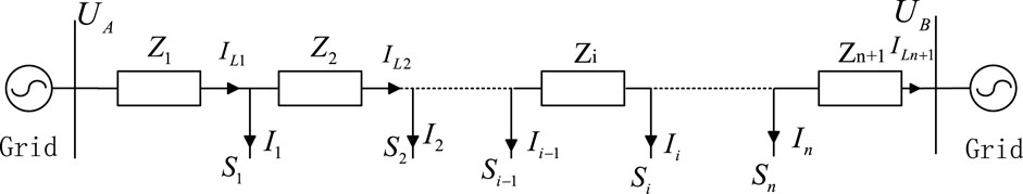
Figure 1. Dual-power active distribution loop network equivalent diagram.
As shown in Figure 1, the dual-power loop network line is divided into n segments.
According to Figure 1, the loop equation is
We assume that the voltages of equivalent load nodes are all
The complex power output at both ends of the line is obtained as follows.
It can be seen from Eq. 4 that the output power at both ends of the feeder of the dual-power distribution loop network caused by the access of distributed power sources is composed of two independent parts. The first part of the power is related to the equivalent load of each branch and the impedance of the whole system, which is the power transmitted by the distribution network to the power load. The second part of the power is related to the voltage difference between the two ends of the feeder and system impedance, independent of the power load, and only flows in the ring network. The second part of the power will cause additional line loss, which not only causes the heating of the distribution line but also affects the economic operation of the distribution network. This part is called circulating power.
It can be seen from Eq. 4 that the voltage difference between the two ends of the line is the main reason for line loss. In order to eliminate the circulating power and reduce the active loss of the line, the existing method involves installing the expensive centralized unified power flow controller and other power flow control equipment at the first or end of the line. However, the centralized power flow control equipment has the problems of large area, poor flexibility, and low-cost performance, which is not suitable for the active distribution network with intensive load and a complex grid structure. The distributed power flow controller is composed of multiple sub-modules. Due to the modular design of the distributed power flow controller, it can be distributed on the transmission line, the tower, or the sub-station, which can meet the actual multi-scene control requirements of the distribution network project (Zhang et al., 2020). The access mode and topology of the distributed power flow controller system are shown in Figure 2.
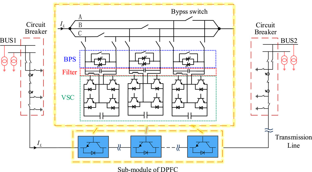
Figure 2. Access mode and topology of the distributed power flow controller system.
The distributed power flow controller is composed of three DPFC sub-modules, which are mounted in three-phase lines, as shown in Figure 2. Each sub-module of the distributed power flow controller is composed of a bypass switch, thyristor bypass switch, filter circuit, voltage source converter, and DC capacitor. Each sub-module can be controlled independently, which avoids the disadvantages of redundancy in centralized three-phase equipment and solves the problem of difficult phase separation control.
In this paper, each sub-module of the distributed power flow controller is arranged in each section of the active distribution network according to the needs, as shown in Figure 3.
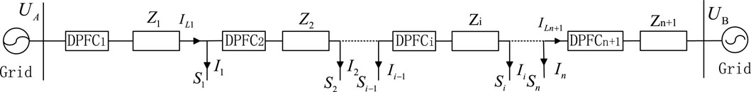
Figure 3. Schematic diagram of the distributed power flow controller connected to the distribution line.
Tang et al. (2018) showed that the distributed power flow controller can be equivalent to the impedance mode, power mode, and voltage source mode. The distributed power flow controller is equivalent to a voltage source with variable phase angle and amplitude. Thus, Figure 3 can be equivalent to Figure 4.
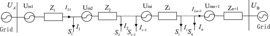
Figure 4. Equivalent circuit of the dual-power loop network with the distributed power flow controller.
At this time, the voltage difference between the two ends of the line is expressed as
where
It can be seen from Eq. 5 that by controlling the size and phase angle of the injected voltage, the voltage difference between the first and last ends of the line is eliminated, and the circulating power of the line is reduced, thereby reducing line loss.
When multiple DPFC devices are arranged in the active distribution ring network to regulate the power flow, if the DPFC compensates a specific voltage to the feeder, the line power flow can be optimized to minimize network loss of system operation. It can be seen from Eqs 4, 5 that the voltage difference between the two ends of the line can be changed by controlling the output voltage of the distributed power flow controller, and then the output power at both ends of the line can be changed. In order to eliminate the circulating power of the line and reduce line loss, a minimum network loss optimization control strategy based on the distributed power flow controller is proposed by establishing the relationship between the output voltage of the distributed power flow controller and line loss. We define that the trunk current with minimum loss of the ring network is expressed as
where
Let the output compensation voltage of the distributed power flow controller be
where
After the distributed power flow controller is put into operation, the loop network trunk current
The circulating current
Since
Substitute Eq 6, 8 into Eq. 10 to obtain
where
In order to minimize the active power loss of the distribution ring network,
When the total output compensation voltage
It can be seen from Figure 3 that each sub-module of the distributed power flow controller is dispersedly connected to the distribution network branch. Each branch parameter is different, and the voltage difference
Since the equivalent load model in the dual-power distribution ring network is a constant current source load, that is,
The distributed power flow controller can reduce the circulating current of the line by outputting a specific compensation voltage. When the circulating current is 0, the active power loss in the distribution loop network is the smallest. The specific implementation steps of the minimum network loss optimization control strategy of the active distribution network based on the distributed power flow controller are shown in Figure 5. The line parameters and operation data of the active distribution network are collected, and Eq. 12 is solved. When the active power loss of the active distribution ring network is the smallest, the distributed power flow controller outputs the total compensation voltage. Then, according to the impedance of each segmented line, Eq. 14 obtains the output of each sub-module of the distributed power flow controller. Finally, the instruction is issued to each sub-module to minimize the active power loss of the line.
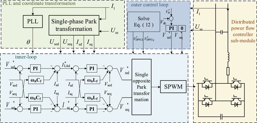
Figure 5. Minimum network loss control strategy block diagram of the distributed power flow controller.
Based on PSCAD/EMTDC, this paper establishes the simulation model of the active distribution ring network with distributed power supply, as shown in Figure 6. The distributed power supply adopts the controlled current source model, and the output of the A side port is set to 1.25 MW. The internal impedance of the B port is set to j1.884 Ω, and the internal impedance of the A port is set to j3 Ω. The line impedance of each section and the load parameters of each node are shown in Table 1. The simulation model on PSCAD/EMTDC is shown in Figure 7.
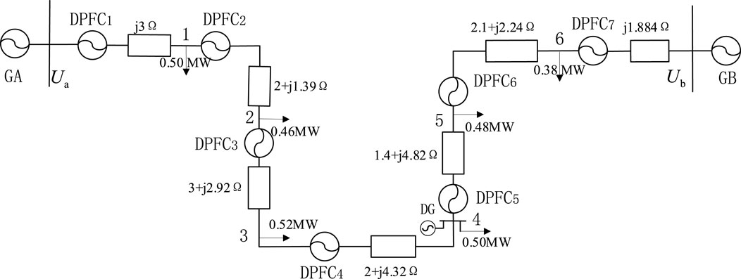
Figure 6. Simulation model.
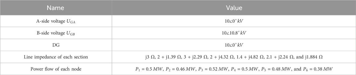
Table 1. Simulation model parameter table.
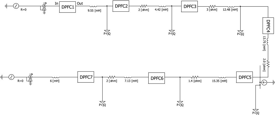
Figure 7. Simulation model of the dual-source ring network based on PSCAD/EMTDC.
Seven distributed power flow controllers and distributed power access node 4 are arranged on each section line. In the simulation process, the process of DG not being put into operation is defined as state 1, the process of DG being put into operation but DPFC not being put into operation is defined as state 2, the process of DG and DPFC being put into operation is defined as state 3, and the state change time is set to 1 s and 1.5 s.
The compensation voltage of the DPFC is 0.956 kV calculated by Eq. 12. The voltage change of each node of the line after compensation is shown in Figure 8.
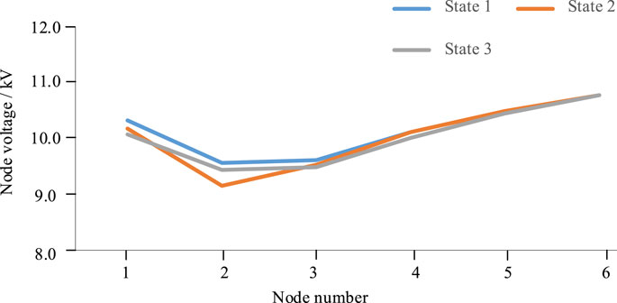
Figure 8. Voltage distribution of each node under state 1 to state 3.
Figure 8 shows that in the case of state 2, due to the access of DG to node 4, the voltage of node 4 is slightly larger than that of state 1 under state 2, but at this time, the voltage of node 2 is lower than the lower limit of voltage fluctuation of 9.30 kV. In state 3, due to the DPFC output compensation voltage regulating the circulating power of the dual power supply loop network, the voltage of each node is re-adjusted within the fluctuation specified value.
When DG is put into operation and the DPFC is not put into operation, the voltage level of node 2 will decrease by more than 7%. It shows that the voltage at the end of the distribution network branch is prone to exceed the lower limit of stable operation. When the DPFC is put into operation, there is no voltage over-limit at each node, which indicates that the strategy employed in this paper can balance the problem of voltage over-limit at some nodes, caused by DG access, in the active distribution network and improve voltage stability.
For the process of minimum network loss optimization control based on the DPFC, the power output on both sides of the active dual power loop network is shown in Figure 9.
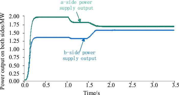
Figure 9. Output of power supply on both sides when node 4 is connected to DG.
It can be seen from Figure 9 that in state 1, the output of the two power sources is 1.925 MW and 1.320 MW, respectively. In the case of the DG input at 1 s, that is, state 2, the output of the two power sources decreases, but the output difference decreases from 0.605 MW to 0.50 MW. In the case of 1.5 s DPFC input for power flow optimization compensation, that is, state 3, the output difference further decreases to 0.1 MW. It can be seen that the distributed power flow controller can effectively reduce the circulating power of the ring network and balance the output of the power sources on both sides when it is put into operation, with the minimum network loss as the goal.
It can be seen from Figure 10 that the total active power of the load is 2.84 MW because the system is a constant power load. Under the condition that both DG and the DPFC are not put into operation, the active power loss of the network is 0.4 MW, and the corresponding active power loss rate of the network is 12.33%. In state 2 after the DG is put into operation, the network loss is alleviated, and the network loss rate is reduced to 8.95% because DG access changes the power output on both sides. After the DPFC is put into control with the minimum network loss as the target, the network loss rate is further reduced to 8.33%.

Figure 10. Comparison of network active power loss in each state when node 4 is connected to DG.
In order to compare the impact of DG access to different locations on the system network loss, the DG access location is changed from node 4 to node 3, and the DG non-input process is defined as state 11. The DG input but DPFC non-input process is defined as state 22. The process of both DG and DPFC input is defined as state 33, and the state change time is also set to 1 s and 1.5 s. The simulation results are shown in Figures 11–13.
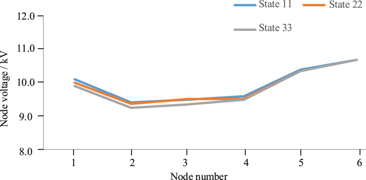
Figure 11. Voltage distribution of each node in different states when node 3 is connected to DG.
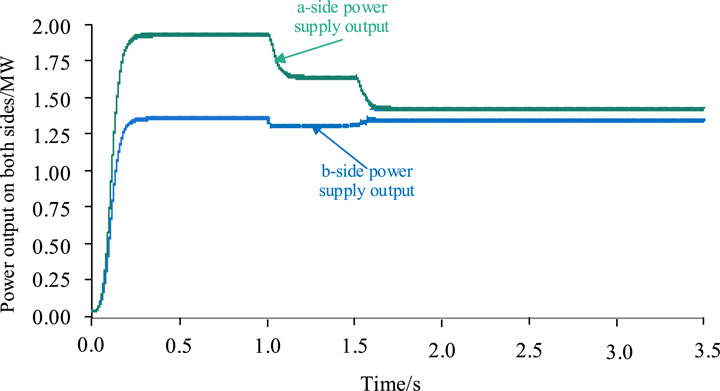
Figure 12. Output of power supply on both sides when node 3 is connected to DG.
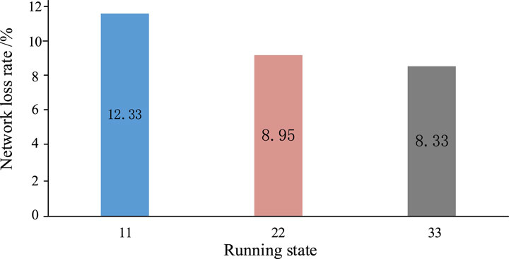
Figure 13. Comparison of network active power loss in each state when node 3 is connected to DG.
It can be seen from the simulation results that when DG is connected at node 3, the output of the two power sources will decrease under the condition of DG input 22, as in the case of DG access at node 4, but under the condition of both DG and DPFC input 33, the output of the power sources on both sides is different from that of DG access at node 4. In state 11, the active power loss rate of the network is 12.33%. In state 2, after the DG is put into operation at node 3, network loss is alleviated because the DG access changes the power output on both sides, and the network loss rate is reduced to 8.72%. In state 33 with the minimum network loss as the target, the network loss rate is further reduced to 8.33%.
The comparison of network loss is shown in Table 2. By comparing the scenarios with and without the DPFC, it can be found that the DPFC can effectively reduce the circulating power of the loop network and the active power loss of the network and balance the output of the power supply on both sides. In addition, no matter where the distributed power supply is connected, the distributed power flow controller can reduce the active power loss of the line to 8.33%. At this time, the corresponding active power loss is 0.365 MW, which effectively reduces line loss and improves the economic operation benefit of the distribution loop network.
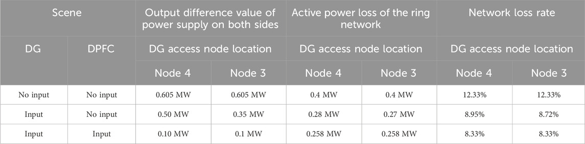
Table 2. Comparison of network loss.
The power distribution characteristics of the loop network operation of the distribution network are analyzed. The distributed power flow controller is distributed on each section of the distribution network. The voltage equation and power equation of the distributed power flow controller acting on the power flow control of the distribution network are established. The line loss index before and after the distributed power flow controller is put into operation is analyzed. An optimal control strategy based on the minimum network loss of the distributed power flow controller is proposed to effectively reduce the circulating power in the line. The simulation results show that compared with other centralized flexible control equipment, the distributed power flow controller can compensate the circulating power potential of the line in sections and is not affected by the distributed power supply. It can not only adjust the voltage of each node but can also effectively reduce the circulating power, reduce the line loss to 8.33%, and effectively improve the safety, stability, and economic reliability of the active distribution network.
The original contributions presented in the study are included in the article/Supplementary Material; further inquiries can be directed to the corresponding author.
ZL: writing–original draft. JW: writing–review and editing. GG: writing–review and editing and investigation. KF: conceptualization and writing–review and editing. XZ: writing–review and editing. FP: validation and writing–review and editing. DG: validation and writing–review and editing. AT: Writing–review and editing and writing–original draft. LM: writing–review and editing, data curation, methodology, and writing–original draft. CX: writing–review and editing.
The authors declare that financial support was received for the research, authorship, and/or publication of this article. The work received funding by the science and technology project of China Southern Power Grid. The project number is GDKJXM20222475.
The authors are grateful to China Southern Power Grid of Power Grid Project for funding.
The authors declare that this study received funding from the China Southern Power Grid. The funder had the following involvement in the study: design, collection, analysis, interpretation of data.
Authors ZL, KF, and FP were employed by Guangdong Power Grid Co., Ltd. Author JW was employed by Electric Power Research Institute of Guangdong Power Grid Co., Ltd. Authors GG and XZ were employed by Foshan Power Supply Bureau of Guangdong Power Grid Co., Ltd. Author DG was employed by Qingyuan Power Supply Bureau of Guangdong Power Grid Co., Ltd.
The remaining authors declare that the research was conducted in the absence of any commercial or financial relationships that could be construed as a potential conflict of interest.
All claims expressed in this article are solely those of the authors and do not necessarily represent those of their affiliated organizations, or those of the publisher, the editors, and the reviewers. Any product that may be evaluated in this article, or claim that may be made by its manufacturer, is not guaranteed or endorsed by the publisher.
Aihong, T., Ma, L., Peng, Q., Jingen, S., Qian, C., Minyuan, G., et al. Research on the harmonic currents rates for the exchanged energy of unified distributed power flow controller[J]. IET Generation, Transm. Distribution, 2022, 17(3): 530–538. doi:10.1049/gtd2.12741
Alam, A., Banerjee, S., Bhattacharya, K., and Panigrahi, C. (2018). “Power loss Reduction & Enhancement of power transfer capability with STATCOM & TCSC using Sensitivity Analysis,” in 2018 International Conference on Recent Innovations in Electrical, Electronics & Communication Engineering (ICRIEECE), Bhubaneswar, India, July, 2018, 3110–3115. doi:10.1109/icrieece44171.2018.9008634
Chen, F., Wang, B., Xu, W., Lu, H., Wu, J., and Lu, C. Influence on the energy conservation of the power system by introducing UPFC [J]. J. Eng., 2019, 16(5):2074–2077. doi:10.1049/joe.2018.8723
Gao, B., Wang, F., Hongyang, Y., Guoliang, Z., Bingbing, S., and Shuqiang, Z. A method of using static synchronous series compensator to suppress subsynchronous oscillation of wind power [J]. Trans. China Electrotech. Soc., 2020, 35(06): 1346–1356.
Hao, W., Meng, Z., Zhang, Y., Xie, Bo, Peng, P., and Wei, J., Carrying capacity evaluation of multiple distributed power supply access to the distribution network with the background of a new power system [J]. Power Syst. Prot. Control, 2023, 51 (14): 23–33.
Jinwei, H., Weiqi, M., Wei, J., and Xiaohua, Y. Analysis and countermeasures of typical problems of power quality in new energy distribution network [J]. High. Volt. Eng., 2023, 49(07): 2983–2994.
Hu, Li, Liu, G., Zhu, L., Xiaoyan, H., Jian, T., and Xinyao, Z. Reliability evaluation of nanjing west ring power system with UPFC [J]. Power Eng. Technol., 2018, 37(01): 26–31.
Islam, M., Safiul Alam, A. M., and Das, C. K. Multi-agent system modeling for managing limited distributed generation of microgrid [J], 2015 2nd International Conference on Electrical Information and Communication Technologies (EICT), Khulna, December, 2015, 2015: 533–538. doi:10.1109/eict.2015.7392010
Kumar, S., Saket, R. K., Kumar Dheer, D., Holm-Nielsen, J. B., and Sanjeevikumar, P. (2020). Reliability enhancement of electrical power system including impacts of renewable energy sources: a comprehensive review. Institution Eng. Technol. 14 (10), 1799–1815. doi:10.1049/iet-gtd.2019.1402
Li, Z., Cai, Ye TANG, Xiafei, C. A. O., Yijia, ZHOU, and Zhifu, ZHOU T. (2023). Collaborative optimization strategy of mobile energy storage devices and distribution network reconfiguration for power loss reduction scenarios. Electr. Power Constr. 44 (09), 137–148.
Luthra, S., Sanjay, K., Garg, D., and Haleem, A., Barriers to renewable/sustainable energy technologies adoption: Indian perspective [J]. Renew. Sustain. Energy Rev., 41, 2015 (41): 762–776. doi:10.1016/j.rser.2014.08.077
Qi, Qi, Jiang, Q., and Xu, Y. (2020). Research status and development prospect of flexible interconnection for smart distribution networks. Power Syst. Technol. 44 (12), 4664–4676.
Rizvi, S., and Abu-Siada, A., A review on active-power-sharing techniques for microgrids [J]. Energies. 2023; 16 (13): 5175, doi:10.3390/en16135175
Ruan, J., Yu, Li, Zhang, L., Chunwen, L., Xueping, Z., Yanxin, Y., et al. Topological design of flexible interconnected smart distribution network with multi-energy complementarity [J]. Electr. Eng., 2023, (15): 229–232+235.
Tang, A., Zhai, X., Lu, Z., Zheng, Xu, and Xu, O., A novel topology of distributed power flow controller for distribution network [J]. Trans. China Electrotech. Soc., 2021a, 36 (16): 3400–3409.
Tang, A., Zhai, X., Lu, Z., Zheng, Xu, and Xu, O., A novel topology of distributed power flow controller for distribution network[J]. Trans. China Electrotech. Soc., 2021b,36 (16): 3400–3409.
Tang, A., Gao, M., Huang, Y., Zhao, H., Xu, Q., and Zheng, Xu. Equivalent model of coordinating energy exchange for series and shunt converters in distributed power flow controller [J] Automation Electr. Power Syst., 2018, 42 (07): 30–36.
Tang, A., Shi, C., Zheng, X. X. U., Qiushi, HUANG, and Yong, ZHAO H. (2020). Optimal power flow with distributed power flow controller based on semi-definite programming method. Automation Electr. Power Syst. 44 (04), 119–125.
Wang, C., Fang, C., Lei, H., Sun, J., Cha, X., et al. Day-ahead and intra-day coordinated scheduling method of active distribution network based on optimal economic operation region [J]. Power Syst. Technol., 2023, 09(18): 1–16.
Wang, F. ', Liu, W. ', Chen, X.WANG W. 2, and Xing, Z. 2 (2020). Evaluation model of synchronous line loss data quality based on penalty variable weight RDA. Electr. Power 53 (12), 223–231.
Wu, Y., Haotian, L. I. U., Xiao, Z., Chen, Z., Peng, L. I. U., Hou, H., et al. Review of incremental distribution network planning considering the uncertainty of source-network-load [J]. Power Syst. Prot. Control, 2021, 49(08): 177–187.
Zekuan, Li, Zhang, F., and Ren, X., Research on reactive power optimal allocation strategy of wind farm considering wind farm loss [J]. Electr. Appl., 2023, 42(05): 9–16.
Keywords: distribution network, circulating current, active power loss, distributed power flow controller, optimal control strategy
Citation: Liu Z, Wang J, Guo G, Feng K, Zhan X, Peng F, Gong D, Tang A, Lulu M and Xiang C (2024) Research on the minimum network loss optimization control strategy of the active distribution network based on the distributed power flow controller. Front. Energy Res. 12:1333171. doi: 10.3389/fenrg.2024.1333171
Received: 04 November 2023; Accepted: 29 May 2024;
Published: 19 June 2024.
Edited by:
Rakibuzzaman Shah, Federation University Australia, AustraliaReviewed by:
Vassiliki T. Kontargyri, National Technical University of Athens, GreeceCopyright © 2024 Liu, Wang, Guo, Feng, Zhan, Peng, Gong, Tang, Lulu and Xiang. This is an open-access article distributed under the terms of the Creative Commons Attribution License (CC BY). The use, distribution or reproduction in other forums is permitted, provided the original author(s) and the copyright owner(s) are credited and that the original publication in this journal is cited, in accordance with accepted academic practice. No use, distribution or reproduction is permitted which does not comply with these terms.
*Correspondence: Aihong Tang, dGFoQHdodXQuZWR1LmNu
Disclaimer: All claims expressed in this article are solely those of the authors and do not necessarily represent those of their affiliated organizations, or those of the publisher, the editors and the reviewers. Any product that may be evaluated in this article or claim that may be made by its manufacturer is not guaranteed or endorsed by the publisher.
Research integrity at Frontiers
Learn more about the work of our research integrity team to safeguard the quality of each article we publish.