 Yadong Zhu
 Haifeng Jiao
 Shihui Wang3
 Songshan Chen
- 1College of Electrical, Energy and Power Engineering, Yangzhou University, Yangzhou, China
- 2Yangzhou Polytechnic College, Yangzhou, China
- 3Suzhou Water Conservancy Design and Research Co., Ltd., Suzhou, China
Mixed-flow pumps, which amalgamate centrifugal and axial-flow attributes, play a pivotal role in various sectors due to their high efficiency and versatility. This paper, utilizing numerical simulation and experimental validation, addresses the critical role of impeller blade count in mixed-flow pump performance. It investigates the effect of the number of impeller blades on the energy dissipation mechanism and inlet flow pattern of a mixed-flow pump. The results reveal that dynamic and static interference effects, along with the separation vortex due to flow separation, are the main sources of energy dissipation in the pump. Under part-load and part-overload conditions, the increase in the number of blades contributes to the improvement of the flow pattern and performance but may induce more intense rotating stall effects under part-load conditions. In overload conditions, the increase in the number of blades significantly amplifies the volume of the inlet vortex structure, consequently deteriorating the inlet conditions of the impeller. This study provides valuable insights for the design and optimization of mixed-flow pumps.
1 Introduction
Mixed-flow pumps amalgamate the attributes of centrifugal pumps and axial flow pumps, exhibiting high efficiency and versatile applicability, making them extensively employed in various sectors such as water treatment, agricultural irrigation, and industrial production. The effectiveness of the fluid transfer system and energy efficiency directly hinges on the performance and operational stability of these pumps. Consequently, delving into the energy dissipation mechanisms and optimizing the hydraulic performance of mixed-flow pumps has emerged as a focal point in contemporary research within related domains (Kim et al., 2010).
With the rapid advancement of the social economy, the project’s evolving demands continually elevate, placing increased demands on the performance and operational stability of mixed-flow pumps. In the pump design process, a pivotal factor is the number of impeller blades. This quantity directly impacts the cascade solidity, resulting in variations in the pump’s performance and operational characteristics. Elyamin et al. (2019), employing numerical simulations, scrutinized the influence of different impeller blade numbers on centrifugal pump performance. The findings revealed that, at seven impeller blades, the pump exhibited the highest head coefficient and efficiency, coinciding with the weakest intensity of secondary flow inside the impeller. Kocaaslan et al. (2017) utilized numerical methods to dissect the correlation between the number of impeller blades and the performance of centrifugal pumps, establishing a positive relationship between head and torque with the impeller blade count. Simultaneously, Ramadhan (2019) delved into the impact of impeller blade number on cavitation characteristics in centrifugal pumps, highlighting a substantial influence on cavitation at the suction of the impeller when the blade count was 5. Yang et al. (2012) conducted a comprehensive evaluation of the number of impeller blades’ effects on the performance and pressure pulsation of pumps used as turbines (PAT) through experimental and numerical studies. Their research unveiled that an augmented blade count effectively mitigates pressure pulsation intensity within the device. Al-Obaidi (2020) analyzed unsteady flow behavior in an axial pump, with a particular focus on the coupling effect of the impeller blade count. Their conclusions underscored the sensitivity of pressure, shear stress, axial velocity, radial velocity, tangential velocity, and mean pressure to the impeller blade count. It is evident that the selection of the impeller blade count significantly influences the pump’s performance and operational stability. However, existing studies predominantly concentrate on the impact of impeller blade number on low specific speed pumps, with glaring gaps in research concerning mixed-flow pumps.
During operation, the pump is usually operated at off-rated conditions. Particularly at low flow rates, backflow (Alpan and Peng, 1991) may occur at the impeller inlet. The mixing of backflow with the main stream will lead to changes in the flow angle and significantly deteriorate the flow conditions of the impeller, resulting in energy dissipation, which seriously affects the performance of the device and operational stability (Bing and Cao, 2014). At the same time, existing research shows that the leading edge of the blade on the incoming medium there is a significant crowding effect, which in turn affects the impeller inlet flow and unsteady flow characteristics of the flow channel. The difference in the number of blades will inevitably change the crowding effect to a certain extent. As early as in the 1990s, Abramian et al. (1988) visualized the flow field near the leading edge of impeller blades by laser Doppler velocimetry (LDV), and effectively suppressed the backflow by setting the front perforated disk. Miyabe et al. (2009) based on experiments and numerical simulations found that the fluctuation of the performance of the device under the part-load condition was caused by the reflux of the impeller blades inlet. Based on the Reynolds time-averaged method, Kang et al. (2021) discussed the mechanism of the backflow phenomenon on the cavitation behavior and cavitation stability of a typical centrifugal pump, and concluded that the backflow is an important influence factor on the cavitation performance of the device. Immediately after that, Kang et al. (2019) investigated the effect of backflow on cavity volume and found that the generation and collapse of cavities induced by backflow is the main reason for the oscillation of cavity volume. Si et al. (2013) investigated the flow noise of centrifugal pumps under inlet backflow conditions. The flow field analysis shows that the impeller inlet under 0.7 times the design flow rate condition shows backflow, the blade passing frequency and shaft frequency dominate the spectrum of flow-induced noise. Therefore, there is a close relationship between the impeller inlet flow pattern and the performance and operational stability of the device. It is not difficult to find that the existing research mainly focuses on the inlet reflux on the device of cavitation, noise and hydraulic performance of the impact of the inlet from a variety of perspectives to analyze the inlet bad flow generation mechanism, clear with the main flow of the two-way coupling law. However, it must be recognized that, as a key parameter in pump design, the study of different impeller blade numbers on the inlet bad flow state is not yet sufficient. The induction mechanism of the number of blades on the inlet bad flow structure is not clear, and the influence law of the inlet bad flow state on the operation of the pump device under different impeller blade conditions has not been fully grasped.
This paper, based on numerical simulation and experimental validation, centers around a typical mixed-flow pump as the subject of investigation, delving into the variations in internal flow characteristics and energy performance of the device under distinct impeller blade conditions. The primary focus lies on scrutinizing unsteady flow and vortex characteristics within the impeller inlet and inlet pipe across different blade counts. The study illuminates the impact of varying blade numbers on device performance and inlet flow. This not only contributes to the theoretical understanding of internal flow in rotating machinery but also holds significant guidance for the design and optimization of mixed-flow pumps.
2 Geometric model
The focus of this paper is a representative small mixed-flow pump designed for agricultural sprinkler irrigation systems. It operates at a rated flow rate (Qdes) of 30 m3/h and a rated speed (ndes) of 6,000 rpm. The key components of the mixed-flow pump include a closed impeller, a space diffuser, and a chamber. Figure 1 illustrates the meridional shapes of its primary overflow components. Specifically, the impeller features an outer diameter at the inlet (Dh) of 21.6 mm, an inner diameter at the inlet (Ds) of 50 mm, and an outlet width (Wo) of 13 mm. The diffuser includes an outer diameter at the outlet (Dsd) of 50 mm and an inner diameter at the outlet (Dhd) of 21.6 mm.
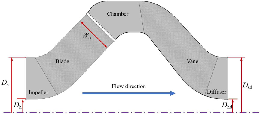
FIGURE 1. Meridian surfaces of overflow components.
3 Numerical model
3.1 3D modeling
A 3D numerical model of the mixed-flow pump is established based on UG NX 12.0, as shown in Figure 2. During the model building process, parametric design is used to introduce adjustable parameters for key geometric components such as blades. This approach significantly simplifies the adjustment and modification of the 3D model, thus ensuring a high degree of consistency between the numerical model and the geometric features of the actual pump. In this study, in order to investigate the effect of different impeller blade numbers on the pump, four independent impeller schemes are set up, with impeller blade numbers of 4, 5, 6, and 7. Meanwhile, the spatial diffuser adopts the determined 7-vane scheme. It is worth mentioning that, in order to ensure the full development of turbulence and thus enhance the accuracy of the prediction results, the inlet and outlet of the model are equipped with extension pipes, the length of which is set to be 10 times the outer diameter of the impeller inlet.
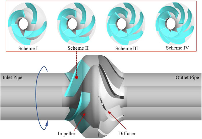
FIGURE 2. 3D modeling of the mixed-flow pump.
3.2 Mesh and irrelevance validation
The quantity and quality of the mesh play a crucial role in numerical calculations, with good mesh quality contributing significantly to the accuracy of numerical computations. Structured meshes, characterized by regularity in geometry and topology, offer a more organized arrangement of nodes and cells. This regularity enhances the solver’s access to data, making it more intuitive and efficient, thereby significantly improving the efficiency and accuracy of numerical computation. In this paper, ANSYS TurboGrid is selected for the automatic generation of structured meshes to complete the discretization of the computational domain.
Simultaneously, to strike a balance between computational cost and accuracy, Scheme II is selected for the mesh independence analysis. In ANSYS TurboGrid, the number of meshes is globally regulated by the Global Size Factor. A larger Size Factor results in a smaller height for the first mesh layer near the wall, yielding a denser mesh. The key indices for the irrelevance test are chosen as the head and efficiency of the device, and a total of five groups of mesh schemes with varying numbers are configured. The numerical prediction results of each group of mesh schemes are given in Figure 3. From the figure, it can be seen that with the encryption of the mesh, the head and efficiency of the mixed-flow pump are gradually reduced. When Size Factor is not less than 1.2, the predicted values of head and efficiency gradually converge, and the relative fluctuation is only 0.22% and 0.04%, which can be considered that the prediction results at this time have been relatively independent of the number of meshes. Therefore, the Size Factor of the mesh used for subsequent numerical calculations in this study is 1.2, and the total number of meshes at this time is 2.36 million, and the total number of nodes is 2.18 million (excluding the extension pipe).
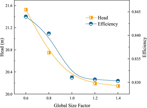
FIGURE 3. Mesh-independent analysis.
In addition, the velocity gradient and pressure gradient of the medium near the wall are high. In order to accurately simulate the boundary layer effect of the flow, the boundary layer mesh is encrypted accordingly. As shown in Figure 4, the mean value of y+ on the blade surface is controlled to be around 30 to meet the requirements of numerical calculations. The final structured mesh scheme used in this numerical simulation study is shown in Figure 5.
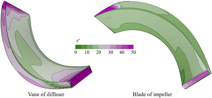
FIGURE 4. Distribution of y+ values on the blade surface.
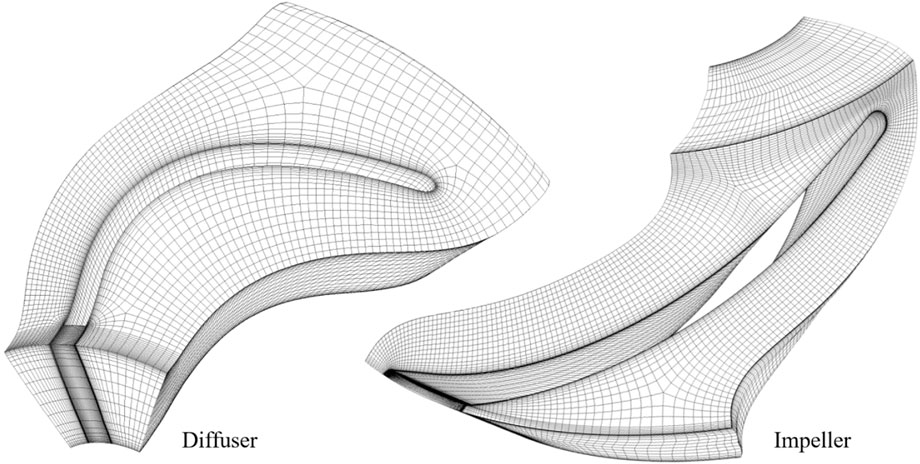
FIGURE 5. Structured meshes for the diffuser and impeller.
3.3 Numerical scheme and boundary condition
Turbulence is a complex flow phenomenon characterized by kinematic structures at various scales. The direct resolution of turbulence is computationally expensive. Consequently, a turbulence model based on the Reynolds-Averaged Navier-Stokes (RANS) equations is incorporated into numerical simulations to approximate turbulence behavior at a relatively lower computational cost. With the mixing pump’s rated speed reaching 6,000 rpm, the internal flow is expected to exhibit strong unsteady characteristics (Wang et al., 2023). The SST k-ω turbulence model, accounting for turbulent shear stress transport, is selected for its ability to accurately predict fluid separation under negative pressure gradient conditions. Hence, the SST k-ω turbulence model is employed to close the governing equations.
The equations for the turbulent kinetic energy k and the specific dissipation rate ω are as follows (Menter, 1994):
where ρ represents fluid density, μt is turbulent viscosity, P stands for the production term, Cω is the coefficient related to the production term, F1 denotes the mixing function, σk and σω are the Prandtl numbers associated with turbulence kinetic energy k and specific dissipation rate ω, respectively. The modeling constant βk is set to 0.09.
The current investigation employs ANSYS CFX for constant calculation with a reference pressure of 1 atm and a constant temperature of 25°C. To enhance numerical convergence, Total Pressure is employed as the inlet condition, with a relative pressure set to 0 Pa, and Mass Flow Rate specified for the outlet. Computational domains are interconnected through the intersection interface, wherein the interface between the rotor and stator necessitates the use of the Frozen Rotor option, with a rotation angle set to 360°. The wall surfaces are designated as no-slip, and the roughness is configured at 10 μm. The solver is set to second-order upwind, with 1,500 iteration steps and a convergence accuracy of 10−5.
4 Experimental verification
To validate the accuracy of the numerical method employed in this study, Scheme II is selected for conducting experiments on the external characteristics of the mixed-flow pump. Figure 6 illustrates the open test bench utilized in this experimental investigation. Two sets of pressure transmitters monitor the inlet and outlet pressures of the mixed-flow pump in real time, with data uploaded for head conversion. The torque meter provides real-time output of the motor’s output torque and speed, uploaded to the RPM and torque collector for pump shaft power monitoring. The electromagnetic flowmeter and solenoid valve work in tandem to adjust and monitor the flow rate in real time. Data from each experimental instrument are uploaded to a computer through a control and data terminal. Except for the electromagnetic flowmeter with a precision level of 0.3, the precision level of each data sampling instrument is 0.2, ensuring the systematic error of the experiment stays within 0.5%. It is noteworthy that the impeller is fabricated from stainless steel precision casting to meet geometric and installation accuracy requirements.
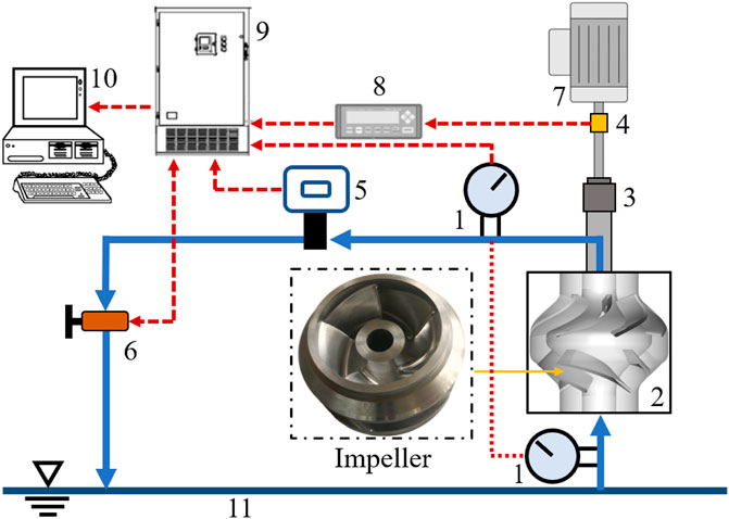
FIGURE 6. Schematic diagram of test bench. 1. Pressure transmitter 2. Pump 3. Coupling 4. Torque meter 5. Electromagnetic flowmeter 6. Solenoid valve 7. Motor 8. RPM and torque collector 9. Control and data terminal 10. Computer 11. Sink.
Figure 7 illustrates the predicted and experimental values of the external characteristics of the mixed flow pump with Scheme II impeller. As evident from the figure, the experimental and predicted values of head and efficiency exhibit a high level of consistency with the flow rate. In general, the predicted values of head and efficiency surpass the corresponding experimental values. This phenomenon can be ascribed to the numerical simulation’s limitation in accurately capturing the volumetric and mechanical losses within the pump. Additionally, the numerical calculations represent highly ideal scenarios, while practical factors such as installation precision and operational stability of the pump unit during experiments may influence the experimental results. However, the relative errors between the experimental and predicted values are 4.9% (head) and 1.5% (efficiency) under the rated flow condition, and the numerical prediction results can be considered to have high accuracy. The above numerical model and method can be used in this research work.
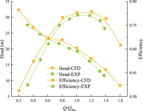
FIGURE 7. Comparison of predicted and experimental values.
5 Results and analysis
5.1 Effect of blade count on performance
Figure 8 compares the hydraulic performance of mixed-flow pumps using impellers with different number of blades. From the figure, it can be seen that there is a significant effect of the number of impeller blades on the performance of the device. The head curves of Scheme III and Scheme IV closely resemble each other at part-load and rated operating conditions. However, as the flow rate continues to rise, the head of Scheme IV gradually becomes smaller than that of Scheme III, with the difference between the two increasing. Concurrently, the efficiency of Scheme IV at this juncture is notably lower than that of Scheme III. This observation indicates that under high-flow conditions, a greater number of blades may elevate resistance and friction loss in the flow path, thereby influencing the pump’s performance. Nevertheless, in general, an increased number of blades has a positive impact on the hydraulic performance of the pump device during part-load and part-overload conditions. With an augmented number of blades, the cascade solidity increases, leading to a reduction in the velocity slip of the medium. The smaller velocity slip can effectively improve the flow pattern in the impeller channel and inhibit the generation of unsteady flow structures such as flow separation and secondary flow. However, observation of the flow-head curve can be found. Compared to the mixed-flow pump with fewer impeller blades, the rotating stall effect of the pump in the flow interval of 0.6Qdes-0.8Qdes is more significant when there are more impeller blades. This is due to the fact that a smaller number of blades will significantly enhance the impeller passability. This results in the stalled vortex clusters not being able to be retained in the flow channel, but instead propagating downstream as they are wrapped by the main flow.
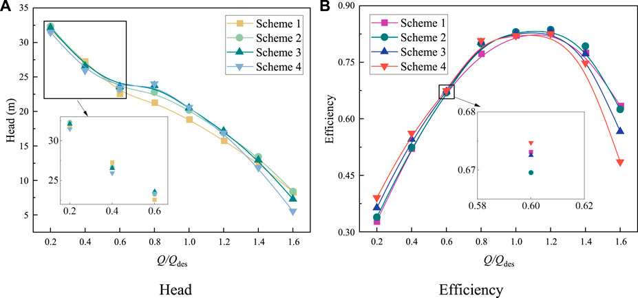
FIGURE 8. Performance of mixed-flow pumps using various sets of impeller. (A) Head (B) Efficiency.
5.2 Effect of blade count on flow characteristics
The vortex transport equation describes the evolution and transport of vortices in a fluid and is expressed as follows (Brown and Line, 2005):
where
In order to further investigate the influence law of the number of blades on the internal flow characteristics of the mixed-flow pump, the VS distributions of the impeller with different numbers of blades in the blade-to-blade cross-section are given in Figure 9 for the filling of the surface streamlines at each flow condition. From the figure, it can be seen that at low flow conditions (0.2 Qdes), a large number of vortex structures appear in the impeller channel of Scheme I and are regularly distributed in the suction side (SS) and pressure side (PS) of the blades. As the flow rate decreases, the flow angle at the impeller inlet also decreases. Consequently, the medium directly impacts the PS of the impeller, leading to the random generation of flow separation and the promotion of separation vortices near the PS of the blade. This vortex structure gives rise to a localized high-pressure region within the flow channel, thereby increasing the pressure gradient between the PS and SS. The pressure gradient is directed from the SS to the PS, which significantly enhances the intensity of the secondary flow in the flow channel. This is the main reason for the flow separation near the SS. It can be observed that at this point, a large area of high VS appears at the impeller outlet, which is the result of the dynamic and static interference of the outflow medium in the pump chamber. With the increase of the number of blades, the impeller cascade solidity rises, which effectively suppresses the flow separation on the PS side. The separation vortex caused by the secondary flow on the SS side still exists, but the intensity is significantly weakened and shifted to the outlet.
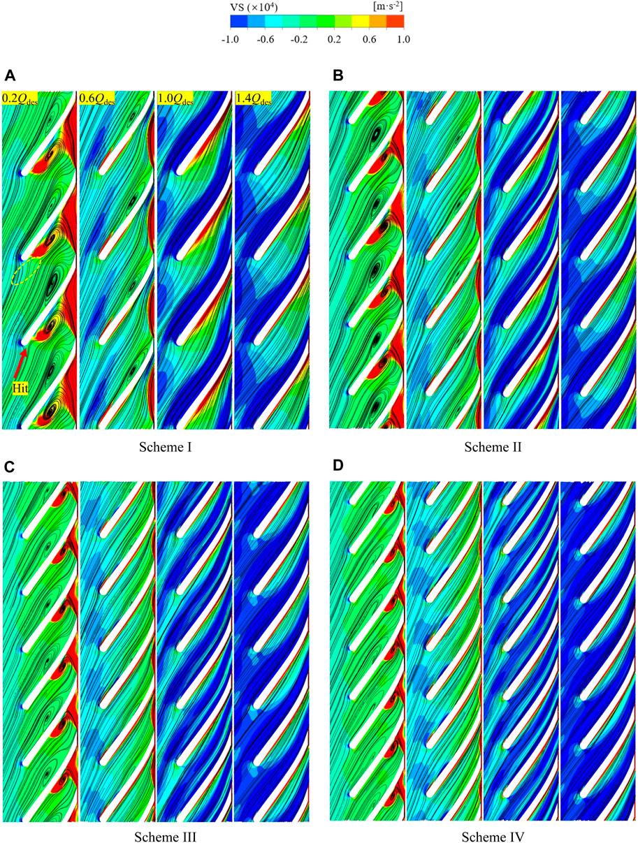
FIGURE 9. VS distribution on impeller blade-to-blade cross section (Span = 0.5). (A) Scheme I (B) Scheme II (C) Scheme III (D) Scheme IV.
As the flow rate increases, the inlet condition of the impeller improves, effectively suppressing all separation vortices within the flow channel. At 0.6 Qdes, small-scale vortex structures can still be observed on the SS of both Scheme I and Scheme II, elongated by the main flow in the direction of the blade bone line. When the number of blades is increased to Scheme III, the flow pattern inside the impeller is good in both part-load and overload condition, and no obvious vortex structure is found. In addition, the intensity of VS near the impeller outlet decays rapidly with the increase of flow rate. However, at this time, a low VS region with regular arrangement appeared on the leading-edge side of each blade of the impeller. This is related to the crowding effect of the blades on the incoming medium.
5.3 Effect of blade count on energy characteristics
The entropy production theory, derived from the second law of thermodynamics, holds significance in thermodynamics, offering a reliable method to quantify and visualize energy dissipation within rotating machines (Hou et al., 2016; Yang et al., 2023). In an independent adiabatic flow system, entropy production includes direct dissipation entropy production, turbulent dissipation entropy production, and wall entropy production, excluding thermal entropy (Ji et al., 2020). It is worth mentioning that since the RANS-based turbulence model is not able to capture the pulsating velocity information within the flow field, the turbulent dissipation entropy production St is computed utilizing the method proposed by Kock and Herwig (2004):
where ρ is the fluid medium density; ω is the turbulent vortex viscous frequency; k represents the turbulent kinetic energy.
Figure 10 illustrates the distribution of entropy production rate (EPR) within the inner flow channel of the mixed-flow pump under different operating conditions. The energy dissipation characteristics are closely linked to flow conditions, with higher EPR observed in part-load conditions for schemes with varying blade numbers. Notably, high EPR regions appear on the SS side of the impeller channel, extending from the inlet to the outlet, indicating energy dissipation due to the “jet-wake” phenomenon. Moreover, the periodic distribution of high EPR areas in the pump chamber aligns with the number of blades. It is noteworthy that a smaller number of blades is associated with a decrease in EPR at the diffuser inlet, indicating potential advantages for optimizing the match between the diffuser and the impeller discharge medium. Additionally, separation vortices near the diffuser outlet are observed during part-load conditions, and with an increase in flow rate under design conditions, the EPR inside the pump experiences a significant decrease. During this phase, the high EPR region is concentrated near the trailing edge of the blade, radiating to the pump chamber. Although the scale of the separation vortex near the diffuser outlet decreases, it remains associated with a higher EPR, affirming the applicability of the entropy production theory in visualizing energy dissipation within the pump.

FIGURE 10. EPR distribution in mixed-flow pumps (Span = 0.5).
With a further increase in flow, the separating vortex near the diffuser outlet disappears when the mixed-flow pump is in overload. This is related to the increase in the strength of the main flow. The higher main flow strength can inhibit the generation of flow separation to some extent. However, compared with the rated condition, although the EPR at the impeller outlet decreases in all schemes, the EPR at the diffuser outlet increases significantly. Especially in Scheme IV, the match between the medium flow angle and the inlet placement angle of the vane becomes significantly worse, and the high EPR region near the outlet of the diffuser occupies almost the whole flow channel.
It is noteworthy to mention that to obtain the comprehensive entropy production of the hydraulic system, one must conduct the relevant volume integrals within the hydraulic system for direct dissipation entropy production rate and turbulent dissipation entropy production rate, along with the corresponding area integrals for the wall entropy production rate. The integrated results are summed to obtain the total entropy production of the hydraulic system. Figure 11 provides a quantification of the entropy production for the mixed-flow pump under various flow conditions. The figure reveals that, at small flow conditions, the entropy production of the impeller decreases with an increase in the number of impeller blades. Conversely, the entropy production in the diffuser exhibits a trend of increasing and then decreasing with the number of blades, reaching its maximum value at Scheme III. During this scenario, the total entropy production of the pump is maximized at Scheme II and minimized at Scheme IV. Under design conditions, the distribution of entropy production in the primary overflow components is more uniform, and the total entropy production is minimized at Scheme II. In overload conditions, the energy dissipation of the impeller increases with the number of blades, and the total entropy production is also minimized at Scheme II.
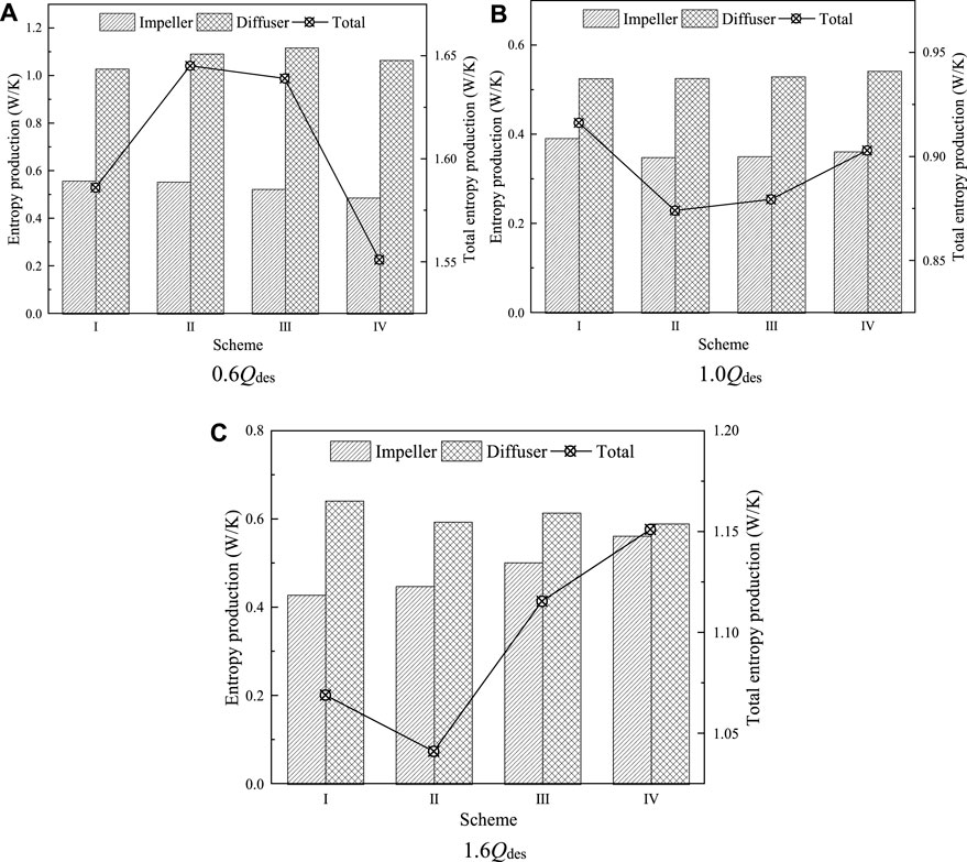
FIGURE 11. Entropy production of mixed-flow pumps at different flow conditions. (A) 0.6Qdes (B) 1.0Qdes (C) 1.6Qdes.
5.4 Effect of blade count on inlet flow pattern
To explore the impact of the number of impeller blades on the inlet flow pattern of the mixed-flow pump, Figure 12 presents the pressure distribution at the impeller inlet with the vortex structure in the inlet pipe for each scheme at different flow conditions. The vortex structure is identified using the Q criterion with the level set to 0.0002 and visualized using vorticity. The figure reveals a strong correlation between the number of relative high-pressure regions in the impeller inlet and the number of impeller blades, indicating a significant crowding effect of the impeller blades on the incoming flow.

FIGURE 12. Pressure distribution with vortex structure in the inlet pipe.
During part-load conditions, the inlet vortex primarily distributes on the inner surface of the pipe. With an increase in flow rate, the vortex structures progressively shift towards the outer pipe wall. Their volume steadily increases, and they merge, ultimately distributing on the outer surface of the pipe under overload conditions. Furthermore, the number of vortex cores corresponds to the number of blades in the separated state of the vortex structure. The substantial increase in the number of blades during design and overload conditions significantly amplifies the volume of vortex structures in the inlet pipe, adversely affecting the inlet conditions of the impeller and impacting the device’s performance. This phenomenon explains the higher entropy production of the mixed-flow pump in design and overload conditions, contrasting with lower entropy production in the part-load condition, as depicted in Figure 11.
6 Conclusion
In this comprehensive study, the impact of varying the number of impeller blades on the internal flow characteristics and energy performance of a mixed-flow pump is thoroughly examined through numerical simulation and experimental validation. The key findings are summarized as follows:
1) The employed numerical method, validated through performance experiments, demonstrates high accuracy with slight overestimation (4.9% for rated head, 1.5% for efficiency) compared to experimental values. The adopted numerical scheme and SST k-ω turbulence model prove to be accurate and applicable for simulating mixed-flow pumps.
2) The study reveals that an increased number of blades under part-load and part-overload conditions enhances flow patterns and pump performance. However, a higher blade count may elevate flow resistance, particularly in the 0.6Qdes-0.8Qdes flow range, leading to a more pronounced rotating stall effect.
3) Augmenting the number of blades significantly increases cascade solidity, improving undesirable flow structures. The primary source of energy dissipation, identified as the separation vortex, decreases within the impeller under low-flow conditions with an increased number of vanes. Conversely, impeller entropy production rises with an increased number of blades under overload conditions.
In summary, this study validates the numerical method’s accuracy in simulating mixed-flow pumps and highlights the impact of blade count on flow patterns, performance, and energy dissipation. While an increased number of blades enhances flow patterns and mitigates undesirable structures, careful consideration is needed to manage elevated flow resistance and potential rotating stall effects. These findings provide valuable insights for the industrial application, design, and optimization of mixed-flow pumps, emphasizing the importance of balancing blade count for optimal performance across varying operating conditions.
Data availability statement
The original contributions presented in the study are included in the article/supplementary material, further inquiries can be directed to the corresponding author.
Author contributions
YZ: Conceptualization, Methodology, Writing–original draft. HJ: Methodology, Writing–original draft. SW: Formal Analysis, Software, Writing–review and editing. ZL: Writing–review and editing. SC: Writing–review and editing.
Funding
The author(s) declare financial support was received for the research, authorship, and/or publication of this article. This research was funded by the Funding for high-end training projects for teachers’ professional leaders in vocational colleges in Jiangsu Province (Grant No. 2023GRFX084).
Conflict of interest
Authors SW and ZL were employed by Ltd.
The remaining authors declare that the research was conducted in the absence of any commercial or financial relationships that could be construed as a potential conflict of interest.
Publisher’s note
All claims expressed in this article are solely those of the authors and do not necessarily represent those of their affiliated organizations, or those of the publisher, the editors and the reviewers. Any product that may be evaluated in this article, or claim that may be made by its manufacturer, is not guaranteed or endorsed by the publisher.
Abbreviations
∇, gradient operator; ∇2, Laplace operator; Cω, coefficient related to the production term; F1, mixing function; k, turbulent kinetic energy; ndes, rated speed; P, production term; Qdes, rated flow rate; St, turbulent dissipation entropy production; v, fluid velocity vector; βk, modeling constant; ρ, fluid density; σk, Prandtl numbers associated with turbulence kinetic energy; σω, Prandtl numbers associated with specific dissipation rate; ω, turbulent vortex viscous frequency; EPR, entropy production rate; LDV, laser Doppler velocimetry; PAT, pumps used as turbines; PS, pressure side; RANS, Reynolds-Averaged Navier-Stokes; SS, suction side; VS, vortex stretching.
References
Abramian, M., Howard, J. H. G., and Hermann, P. (1988). An investigation of axial pump backflow and a method for its control. Turbo Expo Power Land, Sea, Air 79184, V001T01A006. doi:10.1115/88-GT-31
Al-Obaidi, A. R. (2020). Investigation of the influence of various numbers of impeller blades on internal flow field analysis and the pressure pulsation of an axial pump based on transient flow behavior. Heat. Transf. 49 (4), 2000–2024. doi:10.1002/htj.21704
Alpan, K., and Peng, W. W. (1991). Suction reverse flow in an axial-flow pump. doi:10.1115/1.2926503
Bing, H., and Cao, S. (2014). Parametrization of blade leading and trailing edge positions and its influence on mixed-flow pump performance. Proc. Institution Mech. Eng. Part C J. Mech. Eng. Sci. 228 (4), 703–714. doi:10.1177/0954406213490104
Brown, R. E., and Line, A. J. (2005). Efficient high-resolution wake modeling using the vorticity transport equation. AIAA J. 43 (7), 1434–1443. doi:10.2514/1.13679
Elyamin, G. R. A., Bassily, M. A., Khalil, K. Y., and Gomaa, M. S. (2019). Effect of impeller blades number on the performance of a centrifugal pump. Alexandria Eng. J. 58 (1), 39–48. doi:10.1016/j.aej.2019.02.004
Hou, H., Zhang, Y., Li, Z., Jiang, T., Zhang, J., and Xu, C. (2016). Numerical analysis of entropy production on a LNG cryogenic submerged pump. J. Nat. Gas Sci. Eng. 36, 87–96. doi:10.1016/j.jngse.2016.10.017
Ji, L., Li, W., Shi, W., Tian, F., and Agarwal, R. (2020). Diagnosis of internal energy characteristics of mixed-flow pump within stall region based on entropy production analysis model. Int. Commun. Heat Mass Transf. 117, 104784. doi:10.1016/j.icheatmasstransfer.2020.104784
Kang, W., Zhou, L., Liu, D., and Wang, Z. (2021). Backflow effects on mass flow gain factor in a centrifugal pump. Sci. Prog. 104 (2), 003685042199886. doi:10.1177/0036850421998865
Kang, W. Z., Zhou, L. J., Wang, Z. W., and Wang, W. (2019). Analysis of backflow effect in a centrifugal pump. In IOP conference series: earth and environmental science. IOP Publ. 240 (3), 032007. doi:10.1088/1755-1315/240/3/032007
Kim, J. H., Ahn, H. J., and Kim, K. Y. (2010). High-efficiency design of a mixed-flow pump. Sci. China Ser. E Technol. Sci. 53 (1), 24–27. doi:10.1007/s11431-009-0424-6
Kocaaslan, O., Ozgoren, M., Babayigit, O., and Aksoy, M. H. (2017). Numerical investigation of the effect of number of blades on centrifugal pump performance. AIP Publ. 1863 (1). doi:10.1063/1.4992181
Kock, F., and Herwig, H. (2004). Local entropy production in turbulent shear flows: a high-Reynolds number model with wall functions. Int. J. heat mass Transf. 47 (10-11), 2205–2215. doi:10.1016/j.ijheatmasstransfer.2003.11.025
Menter, F. R. (1994). Two-equation eddy-viscosity turbulence models for engineering applications. AIAA J. 32 (8), 1598–1605. doi:10.2514/3.12149
Miyabe, M., Furukawa, A., Maeda, H., and Umeki, I. (2009). Investigation of internal flow and characteristic instability of a mixed flow pump. Fluids Eng. Div. Summer Meet. 43727, 315–321. doi:10.1115/FEDSM2009-78277
Ramadhan Al-Obaidi, A. (2019). Monitoring the performance of centrifugal pump under single-phase and cavitation condition: a CFD analysis of the number of impeller blades. J. Appl. Fluid Mech. 12 (2), 445–459. doi:10.29252/jafm.12.02.29303
Si, Q., Yuan, S., Yuan, J., and Liang, Y. (2013). Investigation on flow-induced noise due to backflow in low specific speed centrifugal pumps. Adv. Mech. Eng. 5, 109048. doi:10.1155/2013/109048
Wang, H., Yang, Y., Xi, B., Shi, W. D., Wang, C., Ji, L. L., et al. (2023). Inter-stage performance and energy characteristics analysis of electric submersible pump based on entropy production theory. Petroleum Sci. doi:10.1016/j.petsci.2023.10.032
Yang, S. S., Kong, F. Y., Qu, X. Y., and Jiang, W. M. (2012). Influence of blade number on the performance and pressure pulsations in a pump used as a turbine. doi:10.1115/1.4007810
Keywords: mixed-flow pump, number of blades, energy characteristics, flow separation, flow pattern
Citation: Zhu Y, Jiao H, Wang S, Lu Z and Chen S (2024) Impact of impeller blade count on inlet flow pattern and energy characteristics in a mixed-flow pump. Front. Energy Res. 11:1346674. doi: 10.3389/fenrg.2023.1346674
Received: 29 November 2023; Accepted: 19 December 2023;
Published: 08 January 2024.
Edited by:
Leilei Ji, Jiangsu University, ChinaCopyright © 2024 Zhu, Jiao, Wang, Lu and Chen. This is an open-access article distributed under the terms of the Creative Commons Attribution License (CC BY). The use, distribution or reproduction in other forums is permitted, provided the original author(s) and the copyright owner(s) are credited and that the original publication in this journal is cited, in accordance with accepted academic practice. No use, distribution or reproduction is permitted which does not comply with these terms.
*Correspondence: Songshan Chen, eXpjc3MwOEAxNjMuY29t