 Rui Song1
 Junjie Si
 Xiaoyue Chen
- 1Electric Power Scientific Research Institute, State Grid Qinghai Electric Power Company, Xining, China
- 2School of Electrical Engineering and Automation, Wuhan University, Wuhan, China
A fault self-driven current limiter is proposed in the paper, which uses a special fault current direct-driven electromagnetic repulsion mechanism to realize the first half-wave of the fault current over the zero point into the current-limiting reactance. The paper analyzes the working principle of the self-driven electromagnetic repulsion mechanism, establishes the equivalent model of the mechanism, and simulates the dynamic characteristics of the electromagnetic repulsion mechanism through the calculation of the double-layer iterative algorithm in time and space. The LC oscillation loop test platform is built, and the stroke–time curve of the prototype is measured. In the test, the prototype is driven by a 3 kA current, and the first half-wave stroke (FHWS) is 3.55 mm past the zero point, which is consistent with the simulation and test results. The effects of structural parameters such as the radius, thickness, and number of turns of the self-driven electromagnetic repulsion mechanism on the dynamic characteristics of the electromagnetic repulsion mechanism are investigated, and it is found that the first half-wave stroke can be significantly improved by increasing the number of turns and outer diameter of the coil. The optimum height of the dynamic repulsion coil is approximately 3 mm.
1 Introduction
With the expansion of the scale of the power system, the grid connection is getting closer and closer, the electrical equivalent distance within the network is further shortened, and the level of short-circuit current in the power system is increasing year by year, which has now become an important problem facing the planning and operation of the power system (Liao et al., 2015; Yang et al., 2011; Liang et al., 2015). Short-circuit current can be limited by using methods such as adjusting the grid structure, changing the mode of operation, and installing current-limiting equipment. A fault current limiter (FCL) is a kind of electrical equipment connected in series in the line (Sun et al., 2008; Liu et al., 2010; Zheng et al., 2014; Chen et al., 2020; Zhang et al., 2021; Wang et al., 2023a); it can immediately and automatically put in the current-limiting impedance when a short-circuit fault occurs in the system within the protection range and effectively limit the short-circuit current to a required reasonable level. According to the composition of current limiting elements, fault current limiters are of solid-state type (Wei et al., 2017), resonant type (Su, 2018), superconducting type (Ni et al., 2021), magnetically controlled reactance type (Chang et al., 2018), and cast reactance type. The study of the FCL based on various structures has become one of the research hotspots.
Lv et al. (2019) proposed a high-voltage fast-switching-type current limiter with multiple breaks connected in series. By equalizing the operating mechanism with the breaks through the isolation transformer and eliminating the insulated tie rods, it can open and close the gate without the system being energized. This scheme requires an external power supply, and the isolation transformer has poor maintainability. Wu (2015) presented an energy-efficient current limiter based on fast switching, which is mounted on a high-voltage insulated platform, where the isolation transformer takes power from both ends of the voltage divider capacitor of the capacitor voltage transformer (CVT) and delivers it to the controller and power box. The system overvoltage may be conducted through the CVT to the energy storage and control unit, causing shocks to the secondary equipment. Wang et al. (2023b) proposed a new type of fault current limiter based on a self-driven varistor; this device can use the energy of short-circuit current to generate electromagnetic force without using measurement, control, or auxiliary equipment. Its structure is simple, and it is less costly, but it can generate less electromagnetic force. Jang et al. (2010); Na et al. (2011) presented a hybrid fault current limiter based on a superconducting inductorless coil. The hybrid fault current limiter consists of a superconducting coil, a fast switch, and a bypass reactor. It uses a high-temperature superconducting coil to generate the magnetic flux, and the fast switch can be actuated by electromagnetic repulsion. It is technically difficult and costly due to the use of superconducting materials. The FCL based on fast switching has already been applied in engineering. Zhang et al. (2021) introduced a 500-kV high-voltage AC FCL based on a high coupling split reactor and studied the breaking characteristics of high-speed switches in the FCL. Chen et al. (2020) introduced an optimization method for fast switching FCL with TRV index, FSFCL withstand voltage, and short-circuit current level as objective functions.
Current fault current limiters based on fast switches are driven by energy storage capacitors. After charging the energy storage capacitor, the power electronic switch is used to control the on–off of the driving circuit of the electromagnetic repulsive mechanism, which in turn controls the action of the fast switch. For the dynamic characteristics and structural optimization of this electromagnetic repulsion mechanism, scholars at home and abroad have carried out extensive and sufficient research. Liu et al. (2020) proposed a quantized design method for the electromagnetic repulsion mechanism considering both the rapidity of the mechanism and the mechanical loads that the mechanism components can withstand and the driving efficiency. Lou et al. (2005) proposed a discrete iterative algorithm based on a two-layer cycle of time and displacement to compute and optimize an electromagnetic repulsion mechanism. Zhang (2019); Zhang et al. (2019) analyzed the efficiency of an electromagnetic repulsion mechanism based on the energy conversion process and proposed a resistance coefficient optimization method. A bidirectional repulsion mechanism is designed in Wang et al. (2023c), and the structure is optimized using the finite element simulation method.
According to a series of studies done by many scholars, analyzing the advantages and limitations of various technologies, this paper proposes a fault current-driven current limiter. After a short-circuit fault occurs, the fault current drives the electromagnetic repulsion mechanism to disconnect the dynamic contacts of the interrupter chamber, and the dynamic contacts of the interrupter chamber are automatically closed after the fault current disappears. This type of current limiter does not need to take an energy device or external power supply, does not drive the fast switching action through a capacitor, and can realize multiple actions in a short period, which has the advantages of a simple structure, high reliability, and good economy. In the research on this type of current limiter, the optimized design of the electromagnetic repulsion mechanism is the key problem. By studying the influence of the change in each structural parameter of the electromagnetic repulsion mechanism on the dynamic characteristics of the fast switch, the action speed of the movable contact is optimized so as to realize that the current-limiting reactance is put into operation at the moment of the first big half-wave of the over-zero moment after the occurrence of the fault.
2 Principle of the self-driving fault current limiter
2.1 Structure of the self-driving fault current limiter
The structure of the fault current-driven current limiter is shown in Figure 1. Under normal operation, current flows through the static repulsion coil and the vacuum interrupter. When a short-circuit fault occurs in the system, the measurement and control device measures the current change and closes the dynamic repulsive coil circuit, the dynamic repulsive coil circuit induces current, and the electromagnetic repulsion between the dynamic and static repulsive coils generates electromagnetic repulsive force from the arc extinguishing chamber to separate the movable contacts. The movable contacts move to the maximum stroke. The holding coil then absorbs the armature so that the switch stays open, and the current-limiting reactor is put into use at the first over-zero point of the fault current. After the fault current disappears, the holding coil current decreases and the contacts automatically return to the closed state.
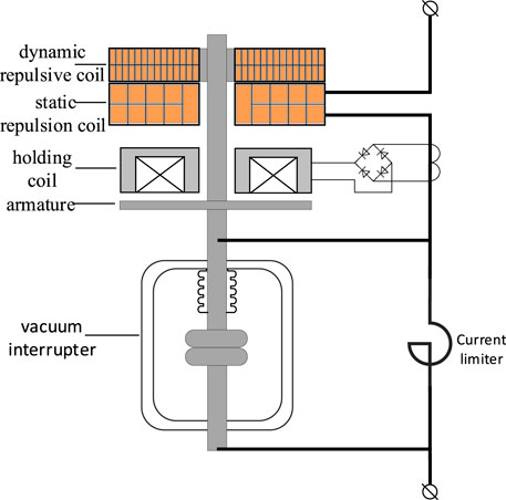
FIGURE 1. Structural diagram of the self-driving fault current limiter.
The static repulsion coils carry both normal system operation and fault currents, so their cross-sectional area cannot be too small from the point of view of temperature rise. The dynamic repulsion coil only carries induced current after a system fault occurs, so the cross-sectional area is not required.
2.2 Application scenarios for the self-driving fault current limiter
The application scenario of the current limiter studied in this paper is shown in Figure 2. The 110/38/11-kV main transformer capacity is 63 MVA, the short-circuit voltage percentage is 10.4%, and the leakage reactance of the main transformer converted to the 110-kV side is approximately 20 Ω. The value of the inductance of the current-limiting reactor is set to be 42.9 mH. The positive-sequence impedance of the system is taken to be 1/10 of the impedance of the main transformer. By calculation, when a three-phase short-circuit occurs in the busbar of the 10-kV side, the short-circuit current reaches 28.87 kA, which exceeds the rated breaking current of the circuit breaker 25 kA, and the fault current limiter limits the short-circuit current to 17.91 kA, with a depth of limitation of approximately 38%. The short-circuit current of the single phase before and after the fault current limitation on the 110-kV side is 2.89 kA and 1.79 kA, respectively. Relay protection equipment sends action signals to the switch when the short-circuit current on the 10-kV side exceeds 20 kA. The relay protection device sends an action signal to the switch when the short-circuit current on the 10-kV side exceeds 20 kA, and at this time, the fault current on the 110-kV side is 2 kA. The electromagnetic repulsion mechanism can act reliably within the scope of the fault current to be limited and realize that the current-limiting reactance is put into operation at the moment when the first half-wave of the fault current passes through the zero point.
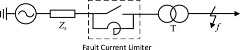
FIGURE 2. Application scenarios of the fault current limiter.
3 Simulation and calculation of the fault current-driven electromagnetic repulsion mechanism
3.1 Principle analysis of the fault current-driven electromagnetic repulsion mechanism
Several scholars have already carried out a lot of research on the capacitive discharge driving method (Liu et al., 2020; Lou et al., 2005; Zhang, 2019; Zhang et al., 2019; Wanget al., 2023c) and proposed many optimization design methods for the structural parameters of the electromagnetic repulsion mechanism. The new electromagnetic repulsion mechanism proposed in this paper is different from the traditional method, in that the driving current is determined by the system state, so the simulation calculation method of the dynamic characteristics is also different.
The self driving electromagnetic repulsion mechanism consists of two coils. Among them, the short-circuit current flows through the static repulsion coil, while the dynamic repulsive coil generates an induced current. Under the action of the magnetic field generated by the current, the repulsive force between the coils drives the contact separation of the vacuum arc extinguishing chamber. The equivalent circuit of the electromagnetic repulsion mechanism is shown in Figure 3. The drive circuit current
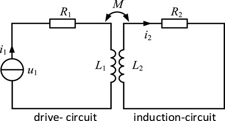
FIGURE 3. Equivalent circuit of the electromagnetic repulsion mechanism.
The equations for the driving and sensing circuits are shown in Eq. 1:
where
The magnetic chain interlinked by each coil includes the magnetic field generated by its current as well as the magnetic field generated by the other coil, so the magnetic chain interlinked by the two coils is written in the following form, and the derivatives and partial derivatives are computed for the variations in Eq. 2 and Eq. 3.
where
Combined with the above equation, Eq. 4 and Eq. 5 can be deduced:
Based on the above relationship, the recursive formula is shown in Eq. 6:
Eq. 7 and Eq. 8 was used to calculate the electromagnetic force and acceleration based on the calculated
where
3.2 Simulation and calculation of the electromagnetic repulsion mechanism based on the double-layer iterative algorithm
According to the time- and space-based double-layer iterative algorithm proposed in Lou et al. (2005), the changes in coil self- and mutual inductance during each iteration are also considered. As shown in Figure 4, at each time step, the induced current
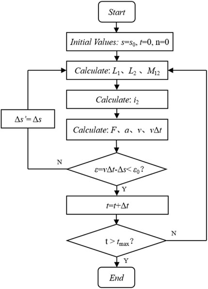
FIGURE 4. Double-layer iterative algorithm flowchart.
3.3 Analysis of finite element simulation of the electromagnetic repulsion mechanism
We study the dynamic characteristics of an electromagnetic repulsion mechanism driving a 24-kV vacuum interrupter with the following structure: a static repulsion coil with a cross-section of 10*9.5 mm, featuring a two-layer structure and an insulation thickness of 0.5 mm between turns, and a dynamic repulsion coil with a cross-section of 0.25*4 mm, featuring a two-layer structure and an insulation thickness of 0.02 mm between turns. The coil materials are copper, the initial distance between coils is 2 mm, and the coil outer diameter is 85 mm. The total mass of tie rods and moving coils is approximately 3 kg. The resistance of the moving contacts during the movement is obtained by measurement. The two-dimensional simulation model of the electromagnetic repulsion mechanism was established using COMSOL finite element simulation software, and the control equations for magnetic field calculation and the electromagnetic repulsion are shown in Eq. 9 and Eq. 10:
The magnetic field distribution at the 1-ms moment obtained from the simulation is shown in Figure 5. Magnetic field coupling dynamic mesh simulation is used to obtain the electromagnetic repulsion mechanism under the action of the stroke-time curve of the moving contact, and the results of the double-layer iterative algorithm described in the previous section are compared. As shown in Figure 6, it can be seen that the results of the finite element simulation are consistent with those of the double-layer iterative calculations.
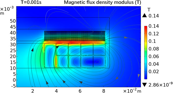
FIGURE 5. Magnetic field distribution at 1 ms in the finite element simulation.
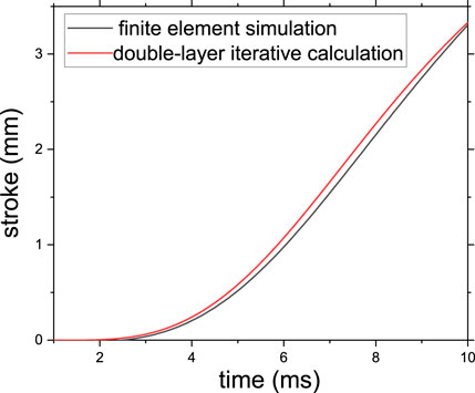
FIGURE 6. Comparison of finite element simulation and double-layer iterative calculation results.
4 Test of the dynamic characteristics of the electromagnetic repulsion mechanism
The LC oscillation test circuit is established, as shown in Figure 7. A 14-mF capacitor and a 0.75-mH inductor form a series resonance circuit with a resonance frequency of approximately 49.1 Hz. The capacitor is charged through the regulator, transformer, and silicon stack. The capacitor voltage
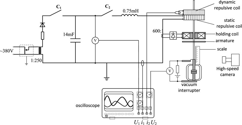
FIGURE 7. LC oscillation circuit test layout.
The waveforms obtained from the test are shown in Figure 8. The peak value of the main loop current is approximately 3000 A, the time constant is approximately 0.1 s, and the first half-wave current waveform is not much different from the sinusoidal waveform, which can approximately simulate the fault current. It can be seen that the contact opening distance reaches its maximum within 20 ms. Afterwards, the switch maintains an open state under the action of the holding coil. When the peak current of the LC oscillation circuit decreases to below 500 A, the switch automatically returns to the closed state.

FIGURE 8. Curve of the test current and moving contacts’ displacement.
For the fault current limiter, the opening distance of the movable contact at the moment when the first half-wave of the current crosses the zero point is more important. Although the current limiter only needs to break the 2.89 kA fault current, considering the risk of re-breakdown of the movable contact caused by the transient recovery voltage, it should be ensured that the movable contact has enough opening distance at the moment of the first half-wave through the zero point to ensure reliable breaking. Figure 9 compares the test waveforms with the results obtained from the simulation, where the solid line represents the test values and the dashed line represents the simulation values. In the first half-wave over the zero point moment, the test and simulation values of the dynamic contact stroke were 3.55 mm and 3.49 mm, respectively, with only a 1.7% difference, and the current and dynamic contact stroke waveforms are closer. The shape of the static repulsion coil is regarded as a square circle in the simulation, which is slightly different from the actual helical coil, resulting in a certain deviation of the mutual inductance calculation results, and the simulation results of the induced current amplitude are small, which leads to the simulation results of the dynamic contact stroke being also small. Considering the small number of turns on the static repulsion coil, the above may be the main reason for the error. The overall error is small, and the simulation and test results are basically consistent, which can verify the accuracy of the simulation model.
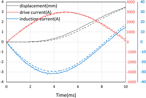
FIGURE 9. Comparison of the test and simulation results in the first half-wave of the current.
5 Analysis of factors affecting the dynamic characteristics of the fault current-driven electromagnetic repulsion mechanism
The dynamic characteristics of the electromagnetic repulsion mechanism are first calculated for peak 2 kA, 3 kA, and 4 kA drive currents. Increasing the drive current can increase the induced current magnitude, thus significantly increasing the electromagnetic repulsion. Figure 10 shows the stroke curve of the moving contact under different driving currents.
FIGURE 10. Stroke curve of moving contact under different driving currents.
Considering that the first half-wave over the zero point moment is the same, approximately 10 ms, and the drive current is close to a sinusoidal half-wave, in different structures, its electromagnetic repulsion and stroke curve are more similar, which can be reflected by the first half-wave over the size of the zero point of the dynamic characteristics. The peak driving current is kept at 3 kA, and the changes in the dynamic contact stroke with the structural parameters of the electromagnetic repulsion mechanism are studied through simulation. The maximum contact stroke limit is not considered in the simulation. As shown in Figure 11, these structural parameters include the height
FIGURE 11. Structural parameter diagram of the electromagnetic repulsion mechanism.
As shown in Table 1, the first half-wave stroke (FHWS) of the fast switch is almost unchanged by changing the thickness b2 of the dynamic repulsion coil. This is because when the number of turns of the dynamic repulsion coil is changed to n times the original, although the mutual inductance

TABLE 1. First half-wave stroke (FHWS) when
As shown in Table 1, increasing the dynamic and static repulsion coil outer diameter
As shown in Figure 12, the first half-wave stroke is maximized at a coil height of 3 mm by changing only the dynamic repulsion coil height
FIGURE 12. Curve of the first half-wave stroke with the height of the moving coil.
Since the static repulsion coil needs to pass the system current, considering the temperature rise problem, the cross-sectional area of the static repulsion coil
FIGURE 13. Curve of the variation of the first half-wave stroke with the structural parameters of the static coil.
6 Conclusion
1) This paper proposes a fault current-driven current limiter that can realize the first half-wave of fault current over a zero point into the current-limiting reactance by fault current-driven electromagnetic repulsion mechanism action.
2) For the electromagnetic repulsion mechanism of the current limiter, the dynamic characteristic simulation model is established by the discrete double-layer iterative algorithm, and the simulation finding is consistent with the experimental results. The opening distance of the interrupter chamber is up to 3.55 mm at the moment of the zero point of the first half-wave under the peak driving current of 3 kA.
3) The analyzed results of the effects of the structural parameters of the electromagnetic repulsion mechanism on the dynamic characteristics can provide a reference for the optimized design of the electromagnetic repulsion mechanism. The first half-wave stroke can be significantly improved by increasing the number of turns and the outer diameter of the coil. The optimal height of the dynamic repulsion coil is approximately 3 mm.
Data availability statement
The original contributions presented in the study are included in the article/supplementary material; further inquiries can be directed to the corresponding author.
Author contributions
RS: writing–original draft. YD: writing–review and editing. XW: writing–review and editing. GF: writing–review and editing. JS: writing–original draft. DW: writing–review and editing. XC: writing–review and editing. SA: writing–review and editing.
Funding
The author(s) declare that financial support was received for the research, authorship, and/or publication of this article. This work was partially supported by the Science and Technology Project of State Grid Qinghai Electric Power Company (No. 522807220008).
Conflict of interest
Authors RS, YD, XW, and GF were employed by State Grid Qinghai Electric Power Company.
The remaining authors declare that the research was conducted in the absence of any commercial or financial relationships that could be construed as a potential conflict of interest.
Publisher’s note
All claims expressed in this article are solely those of the authors and do not necessarily represent those of their affiliated organizations, or those of the publisher, the editors, and the reviewers. Any product that may be evaluated in this article, or claim that may be made by its manufacturer, is not guaranteed or endorsed by the publisher.
References
Chang, L. Y., Yao, L., Deng, J. Y., and Geng, Y. (2018). Parameter design and performance study of magnetron series compensated fault current limiter. Adv. Technol. Electr. Eng. Energy 37 (09), 81–88. doi:10.12067/ATEEE1803014
Chen, X., Liang, Y., Wang, G., and Li, H. (2020). Parameter optimization design method for a fast-switch-based fault current limiter and circuit breaker. Int. J. Electr. Power & Energy Syst. 114, 105377. doi:10.1016/j.ijepes.2019.105377
Jang, J. Y., Park, D. K., Yang, S. E., Young Jae Kim, , Jin Bae Na, , Hyun Chul Jo, , et al. (2010). A study on the non-inductive coils for hybrid fault current limiter using experiment and numerical analysis. IEEE Trans. Appl. Supercond. 20 (3), 1151–1154. doi:10.1109/tasc.2010.2041219
Liang, Y., Yang, J., Meng, K. F., Song, R., Kong, X. P., and Li, C. L. (2015). Analysis of the short-circuit current in the power grid in the Xining and Ri-Yue-Shan area in 2015. Qinghai Electr. Power 34 (03), 30–33. doi:10.15919/j.cnki.qhep.2015.03.0010
Liao, G. D., Xie, X. T., Hou, Y. L., and Li, M. J. (2015). Analysis of the problems of three-phase short-circuit current over-limited of 500 kV bus when UHV connected to Hunan power grid. High. Volt. Eng. 41 (03), 7–753. doi:10.13336/j.1003-6520.hve.2015.03.007
Liu, B., Yu, H. B., Xu, Y. Z., Xiong, J., and Zhu, C. Y. (2020). Design and experiment of high-efficiency electromagnetic repulsion mechanism for engineering application. High. Volt. Eng. 46 (12), 4283–4290. doi:10.13336/j.1003-6520.hve.20191483
Liu, K., Chen, H. K., and Lin, J. (2010). Study situation of applications of fault current limiter in power system. Power Syst. Prot. Control 38 (07), 147–151. doi:10.7667/j.issn.1674-3415.2010.07.035
Lou, J., Li, Q. M., Sun, Q. S., Liu, W. D., and Qian, J. L.(2005). Dynamic characteristics simulation and optimal design of the fast electromagnetic repulsion mechanism. Proc. CSEE (16), 23–29. doi:10.3321/j.issn:0258-8013.2005.16.005
Lv, W., Liu, Y. F., Zhou, Q. W., Fang, T. X., Wang, Z. Y., and Zhang, G. T. (2019). Fast switching high voltage fault current limiter with multiple breakers. Automation Electr. Power Syst. 43 (23), 6. doi:10.7500/AEPS20190415005
Na, J. B., Kim, Y. J., Jang, J. Y., Ryu, K. S., Hwang, Y. J., Choi, S., et al. (2011). Design and tests of prototype hybrid superconducting fault current limiter with fast switch. IEEE Trans. Appl. Supercond. 22 (3), 5602604. doi:10.1109/TASC.2011.2182334
Ni, H., Li, W., Lan, R. D., Xiang, B., Lan, R. D., Ding, P., Tu, T., et al. (2021). Simulation analysis of superconducting fault current limiter to suppress DC component of short circuit current. Adv. Technol. Electr. Eng. Energy 40 (10), 74–80. doi:10.12067/ATEEE2101046
Su, X. S. (2018). Fault current limiter with redundant protection configuration based on ultra-fast switch and series resonant. High. Volt. Appar. 54 (12), 89–95. doi:10.13296/j.1001-1609.hva.2018.12.014
Sun, S. M., Liu, H. S., Li, Q. M., and Zou, L. (2008). A summarization of research on fault current limiter of power system. Power Syst. Technol. 290 (21), 75–79.
Wang, L. N., Liu, Y., and Zhao, Z. Z. (2023c). Structural design and magnetic field analysis of bidirectional coil-plate electromagnetic repulsion mechanism. Power Syst. Technol. 47 (09), 3924–3934. doi:10.13335/j.1000-3673.pst.2022.2035
Wang, R., Liao, M., Duan, X., Xie, D., Feng, Z., and Han, X. (2023a). Development and parameters optimization of a self-driving fault current limiter. Electr. Power Syst. Res. 218, 109187. doi:10.1016/j.epsr.2023.109187
Wang, R. F., Xie, D. Z., Feng, Z. M., Wang, D. Q., Duan, X. Y., and Liao, M. F. (2023b). New fault current limiter based on self-driving rheostat. High. Volt. Eng. 49 (04), 1526–1533. doi:10.13336/j.1003-6520.hve.20220046
Wei, F., Lin, X., Li, Z., Chen, L., and Khalid, M. S. (2017). A new distance protection method considering TCSC-FCL dynamic impedance characteristics. IEEE Trans. Power Deliv. 33 (3), 1428–1437. doi:10.1109/tpwrd.2017.2771276
Wu, X. T. (2015). Research on key technologies of energy-saving fault current limiter based on fast switch. Beijing: North China Electric Power University.
Yang, Z. G., Li, L., Li, Y. X., and Wang, K. (2011). The issue of short-circuit current being out of limitation in the Guangdong power grid and related countermeasures. South. Power Syst. Technol. 5 (05), 90–93. doi:10.13648/j.cnki.issn1674-0629.2011.05.021
Zhang, X. Y. (2019). Research on energy conversion efficiency optimization of electromagnetic repulsion mechanism. Wuhan: Huazhong University of Science and Technology.
Zhang, X. Y., Yuan, Z., Chen, L. X., Zhu, Z. X., He, J. L., and He, J. J. (2019). Study of energy conversion efficiency of electromagnetic repulsion mechanism. Power Syst. Technol. 43 (05), 1849–1855. doi:10.13335/j.1000-3673.pst.2018.1455
Zhang, Y. Z., Xiu, S. X., Tang, Q., Jia, S. L., Chu, B., Mo, W. X., et al. (2021). Interruption characteristics of high-speed switch in 500kV fault current limiter with high coupled split reactance. CSEE J. Power Energy Syst. 9 (4), 1577–1584. doi:10.17775/CSEEJPES.2020.06650
Keywords: fault current limiter, electromagnetic repulsion mechanism, self-driven, dynamic characterization, fast switching, structural optimization
Citation: Song R, Ding Y, Wang X, Fu G, Si J, Wang D, Chen X and Ai S (2024) Research on the dynamic characteristics of the electromagnetic repulsion mechanism of a self-driving fault current limiter. Front. Energy Res. 11:1336582. doi: 10.3389/fenrg.2023.1336582
Received: 11 November 2023; Accepted: 29 December 2023;
Published: 18 January 2024.
Edited by:
Bin Zhou, Hunan University, ChinaReviewed by:
Chao Long, University of Liverpool, United KingdomWangling He, North China Electric Power University, China
Yi Liu, Huazhong University of Science and Technology, China
Copyright © 2024 Song, Ding, Wang, Fu, Si, Wang, Chen and Ai. This is an open-access article distributed under the terms of the Creative Commons Attribution License (CC BY). The use, distribution or reproduction in other forums is permitted, provided the original author(s) and the copyright owner(s) are credited and that the original publication in this journal is cited, in accordance with accepted academic practice. No use, distribution or reproduction is permitted which does not comply with these terms.
*Correspondence: Xiaoyue Chen, Y2hlbnhpYW95dWVAd2h1LmVkdS5jbg==