 Rufei He1
 Jian Qiao
- 1CSG PGC Power Storage Research Institute, Guangzhou, China
- 2State Key Laboratory of Advanced Electromagnetic Technology, Huazhong University of Science and Technology, Wuhan, China
The calculation method of the external fault short-circuit current of large units with clear mechanisms and practicality is of great value in engineering practice. Due to the special AC excitation structure and control mode, the external fault short-circuit characteristics of variable-speed pumped storage units (VSPSUs) are very different from those of conventional units. Therefore, this paper proposes a calculation method for external fault short-circuit current based on a time-domain dynamic circuit. According to the excitation and control characteristics of VSPSUs under external fault, the VSPSU under external fault is divided into two cases: continuous excitation and jumper action. Based on space vector analysis, the time-domain dynamic circuit models are established, respectively. On this basis, the analytical formula of the external fault short-circuit current of VSPSUs is derived by combining the transition boundary conditions of the two cases and the dynamic characteristics of the stator flux linkage. Finally, the comparison with PSCAD/EMTDC simulation results shows that the proposed VSPSUs’ external fault short-circuit current calculation method has high accuracy and practical value, which can meet the needs of primary equipment selection and relay protection of variable-speed pumped storage power plants.
1 Introduction
Compared with the traditional fixed-speed pumped storage units, variable-speed pumped storage units (VSPSUs) have better performance in aspects such as operating range and operating efficiency and get rid of the limitation of traditional units which are only used as planned peak and frequency regulation (Yang and Yang, 2019; Sun et al., 2023; Alizadeh Bidgoli et al., 2020). VSPSUs can provide better support for the decarbonization of the power system, and the construction of large-scale variable-speed pumped storage power plants (VSPSPPs) with VSPSUs as the core has become a new trend (Deng et al., 2022; Lu et al., 2022). In terms of the internal fault and protection research of VSPSUs, the internal fault characteristics of VSPSUs’ stator and rotor windings were analyzed using a multi-loop theory (Niu et al., 2019; He et al., 2022), and the internal fault protection of the excitation winding was proposed based on the characteristics of the stator side branch harmonic circulation method. In the study by (Yin et al., 2022), the VSPSU internal fault model was established based on the stator and rotor multi-branch voltage and flux linkage equations, and the main protection scheme was optimized by simulation calculation. At present, scholars have conducted in-depth research on the internal faults of VSPSUs, but there are few studies on the characteristics of external faults of VSPSUs.
The excitation structure and control mode of VSPSUs are special (Yao et al., 2021; Qiao et al., 2023), and the short-circuit current of external fault is very different from that of traditional synchronous generators. In order to meet the needs of VSPSPP equipment selection and relay protection, it is urgent to study the characteristics and calculation methods of VSPSUs’ external fault short-circuit current. A VSPSU is essentially a large, doubly-fed induction motor, and its characteristics are similar to those of doubly-fed wind turbines, but the excitation system of VSPSUs is more complicated. Referring to VSPSPPs that have been put into construction (e.g., 300MW VSPSPP, Fengning (China) and 250 MW VSPSPP, Tehri (India)), VSPSUs often use multiple sets of parallel neutral-point clamped three-level back-to-back converters for excitation (Desingu et al., 2019; Basić et al., 2021). In addition, in order to protect the converter and the unit, the excitation system of VSPSUs is also equipped with jumper protection, which is similar to the crowbar protection of the doubly-fed wind turbine, and the jumper will act when serious external short-circuit faults occur. However, the jumper protection of VSPSUs often uses thyristors as the switching device, so it can only control the input and does not have control over the cut-out function of the “active crowbar” of the doubly-fed wind turbines (Lopez et al., 2009). The jumper will remain in operation until the generator circuit breaker at the VSPSU terminal acts to eliminate the short-circuit current.
For the study on the external fault short-circuit current of doubly-fed wind turbines, the existing literature usually divides the external faults of doubly-fed wind turbines into non-serious faults in the far zone (continuous excitation) (Kong et al., 2014; Jin et al., 2019) and serious faults in the near zone (crowbar action) (Kong et al., 2015; Wang et al., 2015) cases, respectively, and establishes the equivalent calculation model and then gets the analytical expression of the fault current. However, under non-serious faults, the calculation of short-circuit current is based on the normal operation of the doubly-fed wind turbines during the fault period without considering the impact of ride-through control. (Liang et al., 2010 and Zhu et al., 2017) analyzed the influence mechanism of the low-voltage ride-through control strategy on excitation and established a transient model of doubly-fed wind turbines, considering the influence of the control strategy. In addition, considering that the crowbar will not act instantaneously at the moment of serious fault, the short-circuit current expression of the doubly-fed wind turbines considering the crowbar protection action time is derived using the rotor flux linkage as the connection by (Fan et al., 2019; El-Naggar and Erlich, 2015) proposed a short-circuit current calculation method for double-fed wind turbines considering the control switching process. (Ling, 2022) proposed a general transient analysis method for double-fed wind turbines and obtained the precise analytical formula of the rotor fault current but did not consider the crowbar action and the transient characteristics of the stator current. As far as engineering application is concerned, the form of external fault short-circuit current of doubly-fed wind turbines in existing research is often complicated, and the physical mechanism of each part is difficult to understand. In addition, the analytical formula contains many intermediate variables to be solved, which is not convenient for engineering use.
In order to obtain the analytical formula of VSPSUs’ external fault short-circuit current with a clear physical mechanism and practical engineering significance, this paper regards the external fault of VSPSUs as the conversion process of the dynamic circuit and proposes a calculation method of short-circuit current for the external fault of VSPSUs based on the time-domain dynamic circuit. According to the excitation and control characteristics of VSPSUs, the VSPSU under external faults is divided into two cases: continuous excitation and jumper action, and the dynamic circuit conversion model based on space vector is established for the two cases, respectively. Based on the established dynamic model and transition boundary conditions, combined with the dynamic characteristics of the stator flux linkage, the analytical formula of VSPSUs’ external fault short-circuit current is derived. The simulation results of PSCAD/EMTDC confirm the effectiveness of the calculation method proposed in this paper.
The remaining part of this paper is organized as follows: Section 2 establishes the basic electromagnetic transient mathematical model of the VSPSUs. In Section 3 and Section 4, the dynamic circuit conversion models of the VSPSUs under continuous excitation and jumper action, respectively, are established, and the analytical formula of external fault short-circuit current is derived. Section 5 carries on the simulation verification of the proposed calculation method. Finally, Section 6 gives the conclusion.
2 Electromagnetic transient model of variable-speed pumped storage units
2.1 Space vector model of variable-speed pumped storage unit
The VSPSU adopts a three-phase AC excitation winding structure, where the stator side is directly connected to the grid, and the rotor side is connected to the grid through a multi-stage, parallel, back-to-back converter, as shown in Figure 1.
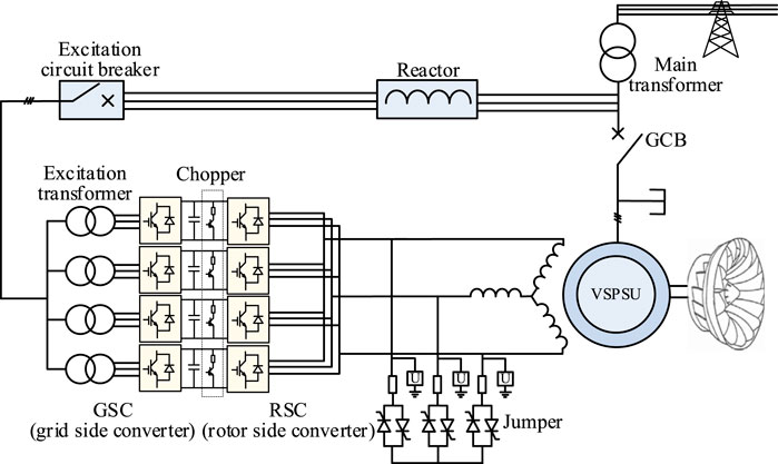
FIGURE 1. Structural diagram of the VSPSU.
If the stator and rotor sides of VSPSUs adopt the motor convention, then by ignoring the magnetic saturation phenomenon of components and converting the rotor side parameters to the stator side, the space vector voltage equation and space vector flux equation of the VSPSUs in the stationary (stator) coordinate system can be obtained as follows (Gonzalo et al., 2011):
Among them,
where p is a differential operator; ψs and ψr are the stator and rotor flux space vectors, respectively; us and ur are the stator and rotor voltage space vectors, respectively; is and ir are the stator and rotor current space vectors, respectively; Rs and Rr are the stator and rotor resistance, respectively; Lm is the excitation inductance; Ls = Lm + Lσs and Lr = Lm + Lσr are the stator and rotor inductance, respectively, where Lσs and Lσr are the stator and rotor leakage inductance, respectively; ωs is the stator voltage and current angular frequency; ωr is the rotor voltage and current angular frequency; and ωm is the rotor angular frequency.
Transforming Eq. 3 will yield the following equation:
It can be seen from Eq. 6 that the VSPSUs external fault short-circuit current (stator current) is jointly determined by the stator flux linkage and the rotor current dynamic characteristics during the fault.
2.2 Dynamic analytical formula of the stator flux linkage under external faults
The stator-side voltage of VSPSUs under normal operation (t < 0) is a space vector with constant amplitude and rotation at synchronous angular frequency, which is defined as follows:
Substituting Eq. 7 into Eq. 1, and ignoring the stator resistance, the steady-state value of the stator flux linkage under normal operation is as follows:
After the external short-circuit fault occurs, the terminal voltage of the variable speed pumped storage unit drops. Therefore, the drop depth is defined as k, and the stator side voltage is as follows:
Combining Eqs. 1 and 6, the dynamic equation of the stator flux linkage is obtained as follows:
The solution of the differential equation can be divided into two parts, the free component ψsn of the flux linkage and the forced component ψsf of the flux linkage. In Eq. 10, the first term is used to generate the forced component of the stator flux linkage, the second term is used to damp the free component of the stator flux linkage, and the third term is used to express the influence of rotor current on the change of the stator flux free component. The stator flux linkage can be expressed as follows:
It can be seen from Eq. 8 that the amplitude of the forced component of the flux linkage is proportional to the grid voltage, so according to Eq. 9, it can be obtained as follows:
Since the flux linkage cannot be mutated, in order to ensure the continuity of the flux linkage before and after the fault, the free component of the flux linkage is generated, so the free component of the flux linkage is a transient component caused by the voltage change. For the current control loop of the variable-speed pumped storage unit, the free component of the flux linkage is equivalent to the disturbance. Generally, the control loop of VSPSUs has a large bandwidth and strong anti-disturbance ability. The rotor current of the free motor will be very small, and the state of the motor is equivalent to the rotor open circuit. Therefore, the free component of the flux linkage will decay with the stator time constant (Gonzalo et al., 2011). According to Eqs. 8, 11, and 12, the free component of the flux linkage is obtained as follows:
Therefore, the dynamic analytical equation of the flux linkage in the event of an external fault is
The solution of the dynamic analytical equation of the VSPSU rotor current needs to be considered according to the excitation control strategy when the external fault occurs. Usually, according to the severity of the voltage drop caused by the external fault, it can be divided into two cases: the continuous excitation of the converter and the action of the jumper. The change of the rotor current in the two cases is different, so the stator short-circuit current also has a large difference when the external fault occurs, which needs to be considered separately.
3 Calculation of stator short-circuit current under continuous excitation
Under the external non-severe short-circuit fault or far-zone short-circuit fault of VSPSUs, the terminal voltage drop is often low. At this time, the jumper will not operate, and the converter will continue to excite. Section 2.2 derives the dynamic analytical equation of the stator flux linkage when the external fault occurs for VSPSUs. The following first derives the rotor current under the condition of continuous excitation of external faults and further obtains the stator short-circuit current under the condition of continuous excitation of external faults.
3.1 Equivalent model of the rotor circuit before the fault
Substituting Eq. 6 into Eq. 4, the relationship between the stator and rotor flux linkage is obtained as follows:
where σ is the flux leakage coefficient,
Figure 2 shows the transformation relationship of the VSPSU space vector mathematical model in different coordinate systems. αβ is the stationary coordinate system; DQ is the rotor coordinate system, which corresponds to the actual rotor angular velocity; and dq is the synchronous coordinate system, which corresponds to the power frequency angular velocity.
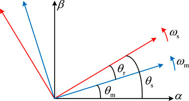
FIGURE 2. Relationship between different coordinate systems.
In order to obtain the actual physical meaning of the rotor loop equation, according to the conversion relationship between different coordinate systems,
where the superscript “r” represents the rotor coordinate system. It can be seen from Eq. 17 that the first item of the rotor circuit equation is the induced electromotive force generated by the stator flux linkage in the rotor winding, that is, the rotor port voltage
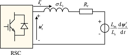
FIGURE 3. Rotor equivalent circuit of the VSPSU.
Multiplying both sides of Eq. 8 by
Equation 18 is further substituted into the former term of Eq. 17 to obtain the rotor port voltage before VSPSU fault.
where s is the slip rate.
3.2 Rotor dynamic circuit modeling and analysis after faults
After an external fault occurs in the VSPSU, the stator flux linkage changes from Eq. 8–14. Multiplying both sides of Eq. 14 by
Substituting flux linkage analytical Eq. 20 into the former term in Eq. 17 and ignoring the
From Eq. 21, it can be seen that the rotor port voltage and the stator flux linkage have the same form when an external fault occurs, and both are composed of a forced component and a free component, denoted as
In addition to the change of the rotor port voltage when an external fault occurs, the RSC output voltage also changes due to the influence of the excitation control. Ignoring the phase angle change, the RSC output voltage changes from
Therefore, after the external fault, the VSPSU rotor circuit equation becomes
The above process can be regarded as a dynamic process in which the rotor circuit switches from a normal operating state to a fault state. According to Eqs. 17 and 25, the rotor dynamic circuit when the fault occurs in VSPSUs is shown in Figure 4.
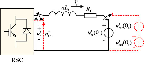
FIGURE 4. Rotor dynamic circuit under continuous excitation of the VSPSU.
The solution of the dynamic circuit consists of two parts. The first part is the forced component (AC component) generated by three excitation sources, and the second part is the free component (DC component) generated due to circuit switching, and the inductive current cannot change suddenly.
First, the superposition theorem is applied to solve the forced component
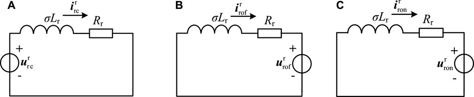
FIGURE 5. Rotor equivalent circuit using superposition theorem. (A) RSC output excitation voltage. (B) Forced component of rotor port voltage. (C) Free component of rotor port voltage.
According to the equivalent circuit shown in Figure 5A and combined with Eq. 24,
According to the equivalent circuit shown in Figure 5B and combined with Eq. 22,
According to Eq. 23, the free component of the rotor port voltage is an AC quantity that rotates clockwise at the electrical angular velocity of the rotor and decays exponentially with the time constant τs. Therefore, the current of the equivalent circuit shown in Figure 5C is also an alternating current that rotates clockwise at the electrical angular velocity of the rotor and decays exponentially with the time constant τs. Therefore,
Adding Eqs. 27, 28, and 29, the forced component of the rotor current is obtained as shown in the following equation:
The free component due to circuit switching is further obtained. According to the circuit theory, the free component can be expressed as follows, where
From the switching law, we know that
The rotor voltage in the normal operating state is defined as follows:
Furthermore, according to the rotor port voltage expression in Eq. 19 under normal operating conditions, the rotor current before the fault is as follows:
According to Eqs. 32 and 34, we can get the following:
According to Eq. 30, we get the following:
Equations 35 and 36 are substituted into Eq. 31 to get the rotor current free component.
Equations 30 and 37 are added to get the analytical equation of the rotor current under the VSPSUs external fault and continuous excitation.
So far, the stator flux linkage analytical Eq. 14 and the rotor current analytical Eq. 38 have been obtained in the case of continuous excitation. Equation 38 is an analytical expression in the rotor coordinate system, and both sides need to be multiplied by
It can be seen from Eq. 39 that the stator short-circuit current in the case of VSPSUs’ external fault and continuous excitation includes three parts, which are the steady-state AC component rotating at synchronous speed, which is produced by the rotor excitation voltage, the forced component of the stator flux linkage and its induced voltage in the rotor, and the transient AC component that rotates at the electrical angular velocity of the rotor and decays exponentially with the time constant τr; this component is a free component that is generated because the inductive current in the rotor equivalent circuit cannot change abruptly and decays with the rotor equivalent time constant τr; the transient DC component that decays exponentially with the time constant τs, which is generated by the free component of the stator flux linkage and its induced voltage in the rotor, decays with the free component of the stator flux linkage and the stator time constant τs.
4 Calculation of stator short-circuit current under jumper action
In the case of severe short-circuit faults near the VSPSU, a large transient energy will be generated on the rotor side, which will cause overvoltage and overcurrent on the rotor side. In order to avoid damage to the VSPSU’s excitation converter, the VSPSU often immediately blocks the converter and puts into the jumper. The jumper of the VSPSU is similar to the crowbar protection of the doubly-fed wind turbines, which short-circuits the rotor winding to the low resistance so that the converter port has a lower voltage when an external fault occurs. At the same time, jumper protection is also a measure for VSPSUs to realize low-voltage ride through.
When the jumper operates, the RSC output voltage becomes zero because the converter is blocked, and the jumper resistance Rc is introduced into the rotor circuit, so the rotor circuit equation after the fault is as follows:
According to Eqs. 17 and 40, the rotor dynamic circuit when an external fault occurs in the VSPSU and the jumper acts is shown in Figure 6.
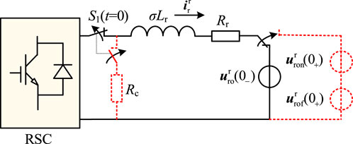
FIGURE 6. Rotor dynamic circuit under jumper action of the VSPSU.
Similar to the case of continuous excitation, the solution of the dynamic circuit shown in Figure 6 consists of two parts, but the first part is the forced component (AC component) generated by two excitation sources, and the second part is the free component (DC component) generated due to circuit switching, and the inductive current cannot change suddenly.
First, the forced component (AC component) generated by the two excitation sources is solved, and the equivalent circuit after applying the superposition theorem is shown in Figure 7.
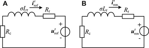
FIGURE 7. Rotor equivalent circuit using superposition theorem. (A) Forced component of rotor port voltage. (B) Free component of rotor port voltage.
According to the equivalent circuit shown in Figure 7A and combined with Eq. (22),
According to Eq. 23, the free component of the rotor port voltage is an AC quantity that rotates clockwise at the electrical angular velocity of the rotor and decays exponentially with the time constant τs. Therefore, the current of the equivalent circuit shown in Figure 7B is also an alternating current that rotates clockwise at the electrical angular velocity of the rotor and decays exponentially with the time constant τs. Therefore,
Adding Eqs. 42 and 43, the forced component of the rotor current is obtained as follows:
The free component due to circuit switching is further obtained. According to the circuit theory, the free component can be expressed as follows, where
Substituting Eqs. 35 and 46 into Eq. 45, the free component of the rotor current is obtained as follows:
Equations 44 and 47 are substituted into Eq. 41 to obtain the rotor current analytical expression when the VSPSU has an external fault and the jumper protection operates.
Equation 48 is an analytical expression in the rotor coordinate system, and both sides need to be multiplied by
It can be seen from Eq. 49 that the stator short-circuit current in the case of VSPSU’s external fault and the jumper protection action includes three parts, which are the steady-state AC component rotating at synchronous speed, which is produced by the forced component of the stator flux linkage and its induced voltage in the rotor; the transient AC component that rotates at the electrical angular velocity of the rotor and decays exponentially with the time constant, a free component that is generated because the inductive current in the rotor equivalent circuit cannot change abruptly and decays with the rotor equivalent time constant; and the transient DC component that decays exponentially with the time constant τs, which is generated by the free component of the stator flux linkage and its induced voltage in the rotor, and it decays with the free component of the stator flux linkage and the stator time constant τs.
Comparing Eqs. 39 and 49, it can be seen that the components of the VSPSU’s short-circuit current under continuous excitation and jumper action have the same form, but there are differences in the amplitude and decay time constant of the current analytical equation. In addition, if the VSPSU’s external fault causes a complete voltage drop (k = 1) and the fault is not removed, the action of the jumper will eventually reduce the short-circuit current to zero in the long-term scale; that is, there is no steady-state component; however, there will always be a steady-state current component under continuous excitation. This is consistent with the actual situation after the action of the jumper.
5 Simulation verification
In order to verify the correctness of the above short-circuit current calculation method for VSPSUs, the external fault simulation model of the variable-speed pumped storage unit was built and verified using PSCAD/EMTDC. The configuration and control of the VSPSUs refer to the 300 MW unit of Fengning variable-speed pumped storage power plants in China, as shown in Figure 8. The relevant parameters of the VSPSU are shown in Table 1. The stator side of the VSPSU is directly connected to the grid through the step-up transformer, and the rated voltage is 15.75 kV. Four sets of parallel 3L-NPC back-to-back converters are used on the rotor side, which can share a maximum slip power of 28 MW and a rated voltage of 3.3 kV. In the excitation control of VSPSUs, the grid side adopts grid voltage-oriented vector control, and the main control goal is to maintain the DC bus voltage stability and the unity power factor with the grid; the machine side adopts stator flux linkage-oriented vector control to realize active and reactive power decoupling control. In addition, the current distribution between multi-channel converters is realized through active current sharing (ACS) control (Selvaraj et al., 2018). The speed of the VSPSU is controlled by the guide vane regulation system of the pump turbine.
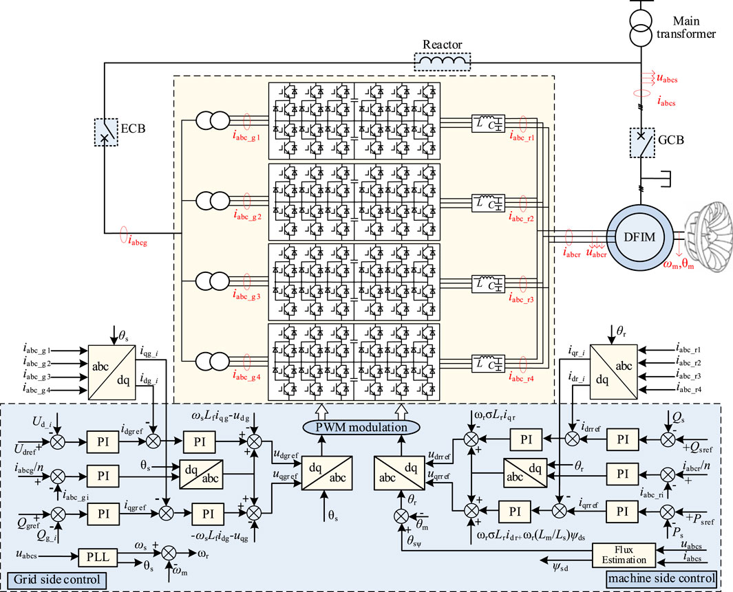
FIGURE 8. Schematic diagram of the variable-speed pumped storage unit control system.
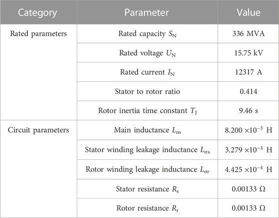
TABLE 1. Parameters of the VSPSU.
The VSPSU initially works in the power generation state with a rated power factor of 0.9; that is, the active power is 302.4 MW and the reactive power is 146.5 Mvar. Furthermore, a three-phase-to-ground short-circuit fault is set at the VSPSU terminal so that the terminal voltage drops to 80% of the rated voltage. At this time, the voltage drop is relatively low, and the converter continues to excite. The fault time is set at the zero-crossing point of phase A, and the simulation and calculation results are shown in Figure 9.
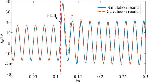
FIGURE 9. Fault current when voltage drops by 20% under continuous excitation.
It can be seen from Figure 9 that the simulation results of stator short-circuit current under continuous excitation control are consistent with the calculation results. In engineering, the effective value of impulse current is often used to check the endurance strength of electrical equipment and the effective value of fundamental wave of the first cycle after the fault is used to check the relay protection. Extracting the first period after the short circuit, the effective values of the simulated and calculated impulse currents are 21.55A and 21.85A, respectively, with an error of 1.4%. The Fourier algorithm is used to extract the fundamental effective values of the first cycle after the fault in the simulation results, and the calculation results are 20.52A and 19.86A, respectively, with an error of 3.2%. It can be seen that the error between the simulation results and the calculation results is small, and the proposed short-circuit current calculation method can effectively calculate the short-circuit fault current under the condition of light voltage drop.
Further verification in the case of jumper action: A three-phase ground short-circuit fault is set at the VSPSU’s machine end, and a smaller fault resistance is set to make the terminal voltage drop to 10% of the rated voltage. At this time, due to the high degree of voltage drop, the rotor current and voltage overshoot are relatively large, and the jumper operates to protect the converter. The fault time is still set at the zero-crossing point of phase A, and the simulation and calculation results are shown in Figure 10.
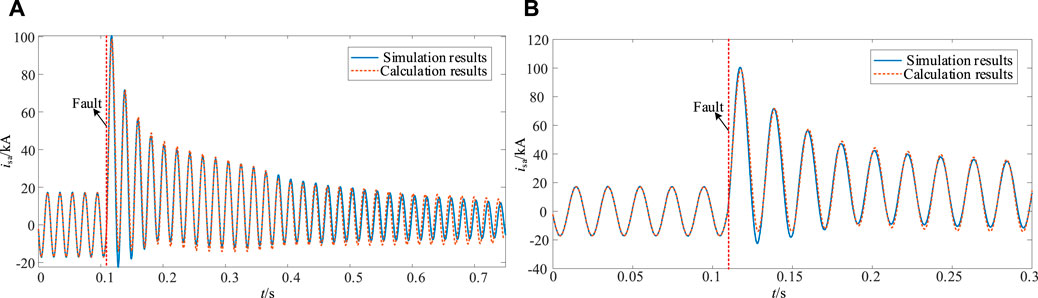
FIGURE 10. Fault current when the voltage drops by 90% under the jumper action. (A) Global graph of current change before and after fault. (B) Enlarged diagram near the fault point.
Figure 10A shows the long-term change of stator short-circuit current when the jumper operates, and Figure 10B shows the change of short-circuit current near the fault point. Extracting the first period after the short circuit, the effective values of the simulated and calculated impulse currents are 57.74A and 58.05A, respectively, with an error of 0.5%. The Fourier algorithm is used to extract the fundamental effective values of the first cycle after the fault in the simulation results and the calculation results are 43.17A and 44.01A, respectively, with an error of 1.9%. It can be seen that the calculation results in a short period of time after the fault are consistent with the simulation results, and the error is small. However, with the extension of the time scale, there is a large error between the calculation results and the simulation results.
Due to the serious short-circuit fault at this time and the long-term input of the jumper, the VSPSU loses its stability in the long-term scale, and the continuous increase of the speed (as shown in Figure 11) will cause the slip rate to continuously vary. In the calculation method, the slip rate before and after the fault remains unchanged by default, so the error between the calculation results and the simulation results will increase with time, which is where the calculation method needs to be further considered and improved. However, in terms of short-term time scale, the short-circuit current calculation method proposed in this paper still has high accuracy under the action of the jumper, which meets the needs of engineering applications.
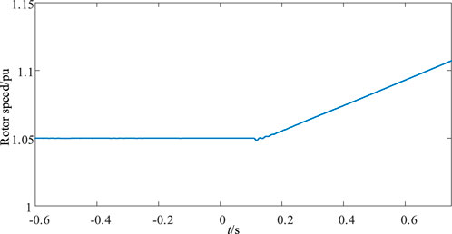
FIGURE 11. Rotor speed change under the jumper action.
6 Conclusion
In this paper, according to the excitation and control characteristics of the VSPSU’s external fault, the VSPSU’s external fault is divided into two cases: continuous excitation and jumper action. Based on dynamic circuit modeling, an external fault short-circuit current calculation method based on the dynamic circuit conversion circuit is proposed, and the following conclusions are obtained:
1) In the case of continuous excitation and jumper action, the VSPSU’s external fault short-circuit current components have the same form, which is composed of steady-state AC components, exponentially decaying transient AC components, and attenuated transient DC components. However, the amplitude of each component of the short-circuit current in the two cases is different, the decay time constant of the transient component is different, and the degree of influence by the external fault is also different.
2) The obtained external fault short-circuit current analytical formula is consistent with the PSCAD/EMTDC simulation results and can reproduce the VSPSU’s external fault short-circuit current variation characteristics. At the same time, the results have good accuracy and practical value and can meet the needs of primary equipment selection and relay protection of variable-speed pumped storage power plants.
Data availability statement
The original contributions presented in the study are included in the article/Supplementary material; further inquiries can be directed to the corresponding author.
Author contributions
RH: conceptualization, formal analysis, and writing–original draft. QL: conceptualization, validation, and writing–review and editing. YM: supervision, validation, and writing–original draft. JQ: data curation, software, and writing–original draft. YL: funding acquisition and writing–review and editing. YP: methodology, software, and writing–original draft. XY: funding acquisition, validation, and writing–review and editing. YL: investigation, resources, and writing–review and editing.
Funding
The authors declare financial support was received for the research, authorship, and/or publication of this article. This research was funded by the Key Technology Project of China Southern Power Grid Co., Ltd., Grant Number STKJXM20210102. The funder was not involved in the study design, collection, analysis, interpretation of data, the writing of this article, or the decision to submit it for publication.
Conflict of interest
The authors declare that the research was conducted in the absence of any commercial or financial relationships that could be construed as a potential conflict of interest.
Publisher’s note
All claims expressed in this article are solely those of the authors and do not necessarily represent those of their affiliated organizations, or those of the publisher, the editors, and the reviewers. Any product that may be evaluated in this article, or claim that may be made by its manufacturer, is not guaranteed or endorsed by the publisher.
References
Alizadeh Bidgoli, M., Yang, W. J., and Ahmadian, A. (2020). DFIM versus synchronous machine for variable speed pumped storage hydropower plants: a comparative evaluation of technical performance. Renew. Energy 159, 72–86. doi:10.1016/j.renene.2020.05.163
Basić, M., Utvić, M., and Dujic, D. (2021). Hybrid modular multilevel converter design and control for variable speed pumped hydro storage plants. IEEE Access 9, 140050–140065. doi:10.1109/access.2021.3118277
Deng, Y. W., Wang, P. F., Morabito, A., Feng, W., Mahmud, A., Chen, D., et al. (2022). Dynamic analysis of variable-speed pumped storage plants for mitigating effects of excess wind power generation. Int. J. Electr. Power Energy Syst. 135, 107453–107517. doi:10.1016/j.ijepes.2021.107453
Desingu, K., Selvaraj, R., Chelliah, T. R., and Khare, D. (2019). Effective utilization of parallel-connected megawatt three-level back-to-back power converters in variable speed pumped storage units. IEEE Trans. Ind. Appl. 55 (6), 6414–6426. doi:10.1109/tia.2019.2936365
El-Naggar, A., and Erlich, I. (2015). Fault current contribution analysis of doubly fed induction generator-based wind turbines. IEEE Trans. Power Electron. 30 (3), 874–882. doi:10.1109/tec.2015.2398671
Fan, X. H., An, D. C., and Sun, S. Y. (2019). Three-phase short circuit current characteristic analysis of doubly fed induction generator considering crowbar protection action time. Trans. China Electrotech. Soc. 34 (16), 3444–3452. doi:10.19595/j.cnki.1000-6753.tces.180957
A. Gonzalo, L. Jesús, and R. Miguel (Editors) (2011). Doubly fed induction machine: modeling and control for wind energy generation applications. Manhattan (New York, U.S. Wiley-IEEE Press).
He, R. F., Qiao, J., Peng, Y. M., Yin, X. G., Wang, Y. K., Zhang, H., et al. (2022). A rotor winding internal short-circuit fault protection method for variable-speed pumped storage units. Appl. Sci. 12 (15), 7783–7819. doi:10.3390/app12157783
Jin, X. L., Cai, X. Y., and Liu, Q. H. (2019). A practical calculation method for short-circuit current of DFIG considering RSC and GSC. Power Syst. Prot. Control 47 (24), 23–30. doi:10.19783/j.cnki.pspc.190269
Kong, X. P., Zhang, Z., and Yin, X. G. (2015). Study of fault current characteristics of DFIG considering impact of crowbar protection. Trans. China Electrotech. Soc. 30 (8), 1–10. doi:10.19595/j.cnki.1000-6753.tces.2015.08.001
Kong, X. P., Zhang, Z., Yin, X. G., and Wen, M. (2014). Study of fault current characteristics of the DFIG considering dynamic response of the RSC. IEEE Trans. Energy Convers. 29 (2), 278–287. doi:10.1109/tec.2014.2309694
Liang, J. Q., Qiao, W., and Harley, R. G. (2010). Feed-forward transient current control for low-voltage ride-through enhance-ment of DFIG wind turbines. IEEE Trans. Energy Convers. 25 (3), 836–843. doi:10.1109/tec.2010.2048033
Ling, Y. (2022). Transient characteristics analysis of DFIG-based wind turbine under symmetrical voltage fault. Proc. CSEE 42 (18), 6871–6880. doi:10.13334/j.0258-8013.pcsee.211452
Lopez, J., Gubia, E., Olea, E., Ruiz, J., and Marroyo, L. (2009). Ride through of wind turbines with doubly fed induction generator under symmetrical voltage dips. IEEE Trans. Ind. Electron. 56 (10), 4246–4254. doi:10.1109/tie.2009.2028447
Lu, Q. H., Yin, X. G., Qiao, J., Wang, Y., Tan, L., and Zhu, L. (2022). Short circuit fault identification and diagnosis analysis of rotor winding for variable speed pumped storage unit. Energy Rep. 8 (13), 34–43. doi:10.1016/j.egyr.2022.08.060
Niu, H. M., Gui, L., and Sun, Y. G. (2019). Simulation and experimental research on stator winding internal faults of AC excitation machine based on multiloop theory. Proc. CSEE 39 (12), 3676–3685. doi:10.13334/j.0258-8013.pcsee.180974
Qiao, J., Yin, X. G., Wang, Y. K., Lu, Q., Tan, L., and Zhu, L. (2023). A rotor ground fault protection method based on injection principle for variable speed pumped storage generator-motor. IEEE Trans. Power Del. 38 (2), 1159–1168. doi:10.1109/tpwrd.2022.3209971
Selvaraj, R., Desingu, K., Chelliah, T. R., Khare, D., and Bharatiraja, C. (2018). Fault tolerant operation of parallel-connected 3L-neutral-point clamped back-to-back converters serving to large hydro-generating units. IEEE Trans. Ind. Appl. 54 (5), 5429–5443. Sept.-Oct. 2018. doi:10.1109/tia.2018.2851581
Sun, D., Zhao, F., Guo, Y., Meng, F., Zheng, W., and Yu, J. (2023). Research on multi-energy cooperative participation of grid frequency inertia response control strategy for energy storage type doubly-fed wind turbine considering wind speed disturbance. Front. Energy Res. 11, 1–18. doi:10.3389/fenrg.2023.1068080
Wang, Y. P., Zheng, T., and Wang, Z. P. (2015). Impact analysis of different slips on the short circuit current of DFIG after crowbar operation. Power Syst. Prot. Control 43 (17), 8–14. doi:10.7667/j.issn.1674-3415.2015.17.002
Yang, W. J., and Yang, J. D. (2019). Advantage of variable-speed pumped storage plants for mitigating wind power variations: integrated modelling and performance assessment. Appl. Energy 237, 720–732. doi:10.1016/j.apenergy.2018.12.090
Yao, W. W., Deng, C. H., and Peng, P. (2021). Optimization method and reduced-order steady-state model for variable-speed pump-turbine unit. IEEE Access 9, 31130–31142. doi:10.1109/access.2021.3059718
Yin, X. G., Qiao, J., and Wang, Y. K. (2022). Optimal configuration of main protection for a variable speed pumped storage power generator based on internal fault simulation. Power Syst. Prot. Control 50 (13), 1–10. doi:10.19783/j.cnki.pspc.226225
Keywords: variable-speed pumped storage units, external faults, short-circuit current, jumper, dynamic circuit, dynamic characteristics
Citation: He R, Lu Q, Ma Y, Qiao J, Li Y, Peng Y, Yin X and Li Y (2023) Calculation method of external fault short-circuit current for variable-speed pumped storage units based on time-domain dynamic circuit. Front. Energy Res. 11:1331512. doi: 10.3389/fenrg.2023.1331512
Received: 01 November 2023; Accepted: 27 November 2023;
Published: 14 December 2023.
Edited by:
Ningyi Dai, University of Macau, ChinaReviewed by:
Jiejie Huang, Nantong University, ChinaKenneth E. Okedu, Melbourne Institute of Technology, Australia
Copyright © 2023 He, Lu, Ma, Qiao, Li, Peng, Yin and Li. This is an open-access article distributed under the terms of the Creative Commons Attribution License (CC BY). The use, distribution or reproduction in other forums is permitted, provided the original author(s) and the copyright owner(s) are credited and that the original publication in this journal is cited, in accordance with accepted academic practice. No use, distribution or reproduction is permitted which does not comply with these terms.
*Correspondence: Jian Qiao, OTA2OTgyNTA3QHFxLmNvbQ==