 Bei Lv1
 Bo Wang
- 1PetroChina Xinjiang Oilfield Company, Karamay, Xinjiang, China
- 2Petroleum Institute, Karamay Campus, China University of Petroleum (Beijing), Karamay, Xinjiang, China
Deep reservoirs have high temperature, high pressure, and high stress. The development of such resources is high cost. Integral fracturing applies one-time well displacement, batch drilling, and batch fracturing. Multiple wells are stimulated with zipper fracturing. It can avoid the interference of the well drilling and fracturing. In this way, the spatial stresses can be utilized to generate the complex fracture network. The dynamic change pattern of the stress field is of great value for the design of integral fracturing. Based on the displacement discontinuity method (DDM) and the fracture mechanics criteria, a whole fracture propagation program is developed to calculate the spatial stress distribution and the whole fracture geometry. The reliability of the program is verified against the classical analytical solutions. Based on the program, this work systematically investigates the effects of the fracture length, the fracturing sequence, the fracture distribution mode, and the injection pressure on the stress field. The main conclusions are as follows: 1) When the fracture half-length is 150 m and the well spacing is 300 m, the staggered fracture distribution mode can ensure uniform fracture propagation and realize the active utilization of inter-well stress field; 2) Compared with the relative fracture distribution mode, the staggered fracture distribution mode is less susceptible to the stress field induced by the adjacent hydraulic fractures, hydraulic fractures tend to propagate along the direction of the maximum horizontal principal stress; 3) The stress field is highly influenced by the in-fracture fluid pressure. The stress interference is stronger with a greater fluid injection pressure and a higher fracture deflection angle will be obtained. It can enhance the fracture propagation resistance and increase the stress value. This work discovers the stress change pattern and lays out a solid foundation for the optimization of the integral fracturing.
1 Introduction
Unconventional oil and gas reservoirs exhibit poor reservoir properties and they have no production under natural conditions. Hydraulic fracturing is an indispensable technique to develop such resources. However, the stimulated volume and the well production are restricted through traditional hydraulic fracturing. Integral hydraulic fracturing, achieved through batch drilling and batch fracturing, enables one-time wellbore placement, one-time fracture placement, and one-time reservoir stimulation. It significantly reduces hydraulic fracturing operation costs, effectively mitigates inter-well interference, greatly enhances reservoir utilization, and maximizes the development benefits of unconventional oil and gas resources (ShiqianQihongSen et al., 2018; Tang et al., 2019). However, compared to single-well fracturing, the integral fracturing scale of the platform well is significantly larger, making it challenging to predict fracture geometry and complex stress field evolution patterns. It is necessary to optimize the treatment parameters and utilize the spatial stress fields during integral fracturing. In this way, the unconventional reservoirs can be fully stimulated and it can maximize the well production.
Under natural conditions, reservoir rocks are subjected to three orthogonal in-situ stresses, the magnitude and the orientation determine the difficulty in creating hydraulic fractures. They also determine the direction of the fracture propagation and well post-fracturing production. Practical experiences in the Permian Basin of the United States have shown that the production of the parent wells can alter the magnitude and the azimuthal orientation of the in-situ stresses, thereby influencing the production of the infill wells (Pankaj, 2018; Zheng et al., 2018). Considering the inter-well stress evolution pattern in Marcellus shale, the optimal well spacing was determined by establishing the relationship between well spacing and single well fracturing scale (Jaripatke et al., 2018). Huang et al. analyzed the effect of the fracturing parameters on the inter-fracture stresses by using the three-dimensional lattice method and the dislocation theory. The results show that when the horizontal principal stress difference is small, it can cause a larger deflection angle and lead to the bifurcation of fractures (Huang et al., 2023). Hu et al. studied the influence of induced stress fields generated by different fracture closure times on the supported fractures through numerical simulations. They found that the induced stress fields rapidly decreased with the closure of hydraulic fractures in formations without natural fractures. In naturally fractured reservoirs, the induced stress fields could promote further fracture propagation (Hu et al., 2021). The above studies indicate that the spatial stress field changes significantly during the integral fracturing process, which affects fracture growth geometry and subsequent well production (Pankaj et al., 2018; Hou et al., 2022).
To simulate real complex fracture morphology and the evolution of stress fields in hydraulic fracturing, both domestic and international scholars have employed various numerical calculation methods. Commonly utilized techniques in this field encompass the Extended Finite Element Method (XFEM) and the Displacement Discontinuity Method (DDM) (Chen et al., 2020; Cong et al., 2021; Zhang et al., 2022). Compared to the traditional Finite Element Method (FEM), the XFEM has greater advantages in handling the intricate geometric shapes and the complex boundary conditions. XFEM can precisely calculate stress and displacement fields around fractures without necessitating alterations to the finite element mesh. This capability enables XFEM to achieve precise simulation and characterization of intricate fracture systems (Saberhosseini et al., 2019; Prieto et al., 2022). The Displacement Discontinuity Method (DDM) is a simulation technique primarily employed for solving complex nonlinear problems within the framework of the Finite Element Method (FEM). By subdividing the modeling domain into multiple discontinuous elements, this method enables the attainment of highly accurate solution results (Saber et al., 2023). In the numerical simulation of hydraulic fracturing, DDM partitions the fracture surface into several smaller units. It solves the distribution of displacement, stress, and strain on each unit to depict the deformation of the rock and the propagation of fractures. This discrete approach allows for a more precise representation of deformation and stress distribution on the fracture surface (Zhang and Sheng, 2020; Hu et al., 2022; Ren et al., 2022). Based on XFEM, Wang et al. investigated the interaction and stress interference during the propagation of two close-spaced fractures. It indicates that the interaction of the adjacent fractures primarily hinges on their relative positions, leading to a classification of fracture relationships into three modes: collinear, staggered, and parallel propagation (Han et al., 2021). Renato et al. utilized the XFEM within a coupled fluid mechanics framework to investigate the impact of stress evolution on fracture propagation. They considered two fracturing construction schemes: sequential and synchronous fracturing. By comparing the analytical solutions with the numerical experimental results, it demonstrated a strong agreement between the two methods (Wang et al., 2023a). Tang et al. addressed the issue of mesh distortion in their work based on DDM. They compared the induced stress of different hydraulic fracture geometries and assessed inter-fracture interference. It identifies the influence of induced stresses on fracture propagation with various geometric shapes (Escobar et al., 2019). Wang et al. employed a cohesive element-based approach to establish a hydraulic fracturing model. The model is in conjunction with multiple hydraulic fracturing experiments conducted under different fracturing sequences. They analyzed the stress interference generated with various fracture spacings. It confirmed that alternate fracturing is more effective than sequential fracturing in controlling the geometric shape of fractures (Wang et al., 2023b). Yang et al. developed a fully coupled pseudo-three-dimensional model using the finite volume method and the displacement discontinuity method. They investigated the influence of stress differences, fracture length, and injection rate on the behavior of complex fracture propagation (Yang et al., 2022). Luo et al. utilized the boundary element method to simulate fluid flow within fractures. They developed a semi-analytical technique based on BEM for evaluating and analyzing the transient pressure behavior in reservoirs. They validated this model and extended it to field cases (Zhang and Yang, 2021). Currently, both domestic and international scholars have conducted extensive research on the impact of stress field evolution on fracture propagation during the hydraulic fracturing process. They have gained a deep understanding of this phenomenon. However, the synergistic effects among different construction parameters in platform wells and their influence on the evolution of the overall stress field are still not well understood (Chen et al., 2022; Dong and Ma, 2022; Liu et al., 2022).
In this study, a comprehensive fracture propagation program was developed based on DDM and fracture mechanics criteria. The accuracy of this program was validated against the classical analytical solutions. Based on the program, the fracture geometry and the stress filed during integral fracturing were calculated in consideration of various key factors, which include the fracture length, fracturing sequence, fracture distribution mode, and injection pressure. Based on the investigation, some effective treatment solutions were proposed to fully develop the unconventional resources.
2 Principle of integral fracturing technology of platform well
The Petrel platform can be applied to obtain the overall fracture geometry during integral fracturing. Petrel Kinetix module can simulate the hydraulic fracturing design based on the on-site construction scheme. Thus, the fracture geometry, conductivity, and spatial distribution can be precisely obtained. Petrel Intersect is a high-resolution reservoir simulator that captures all unconformity and reservoir structure changes with a high level of detail, improving the accuracy and efficiency of field development planning and reservoir management. The workflow enables detailed reservoir characterization, accurate fracture propagation prediction, flexible field management strategies and efficient production performance prediction. As shown in Figure 1, integral fracturing is a promising technology that puts significant emphasis on efficient well placement, completion, and three-dimensional fracturing. This approach not only enhances the stimulation efficiency but also lowers the operation costs, enabling the economic development of unconventional oil and gas resources. It can obtain vertical multi-layer deployment and three-dimensional development. Integral fracturing comprises three key technologies: low-cost and high-efficiency drilling technology, optimization design technology of spatial staggered well layout, and factory operation technology. The well drilling speed can be greatly enhanced and the drilling cost can be significantly reduced. Optimizing well spacing and discovering the spatial and temporal distribution of stress can realize the full sweep of the reservoirs (Yoshioka et al., 2021; Wang et al., 2022; Zhao et al., 2022).
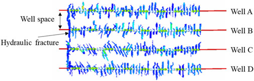
FIGURE 1. Hydraulic fracture geometry during integral fracturing of 4-well platform.
During multi-well integral fracturing, the size and the direction of the local stress field change dynamically due to the competing propagation of multiple fractures. It in turn results in the mutual interference among multiple fractures, multiple stages, and multiple wells. The spatial stress field significantly influences fracture effectiveness and well production. Based on the production data of the offset wells, inter-well interference has three kinds of effects on the stimulation results and the well production: positive effects, negative effects, and negligible effects (Escobar et al., 2019). The positive effects can increase the fracture complexity, enlarge the stimulation volume, lower the pressure attenuation, enhance the cumulative production, and reduce the water content. Conversely, the negative effects are primarily characterized by uneven injection across different perforation clusters. The fracturing fluid and the proppant can flow from the operation wells to the offset wells. The stimulated volume can be reduced and the fluid pressure decays rapidly. The well cumulative production will be greatly lowered. The negligible effects occur when the wellhead pressure and the production rate of the offset wells remain constant. The stimulation volume and the injection pressure are determined by the reservoir properties and the treatment parameters of the operation wells.
As shown in Figure 2, there are three kinds of inter-well interference during integral fracturing of platform wells. The first one is pressure wave interference, the injection fluid does not penetrate from the treatment well into the offset well. As shown in Figure 2A, the fractures have no fluid communication. In this way, the front zone of the fracture remains in a tensile state induced by the pressure wave interference. The permeability of the formation can be greatly enhanced and the reservoir fluid can flow into hydraulic fractures with low resistance. The second one is fracturing fluid interference, the fracturing fluid flows from the treatment well to the offset well. As shown in Figure 2B, the blue zone represents the fluid flow region, and the orange zone represents the proppant flow region. The two fractures have fluid communication. In this way, the injection fluid within the treatment well will be produced in the offset well. The injection fluid cannot create hydraulic fracture and the stimulation volume will be greatly reduced. It hurts well production. The last one is proppant interference, the proppant flows from the treatment well to the offset well. As shown in Figure 2C, the two fractures have proppant communication. In this way, the proppant cannot prop the whole fracture surface, fracture conductivity cannot meet the requirement of well production. Moreover, the effect of proppant interference can last a long time due to the propped hydraulic fractures. The pressure wave interference can enhance the formation permeability. The fracturing fluid interference and the proppant interference can cause strong fracture competition and conductivity reduction. It is of great value to obtain the pressure wave interference and avoid the fluid and proppant interferences.
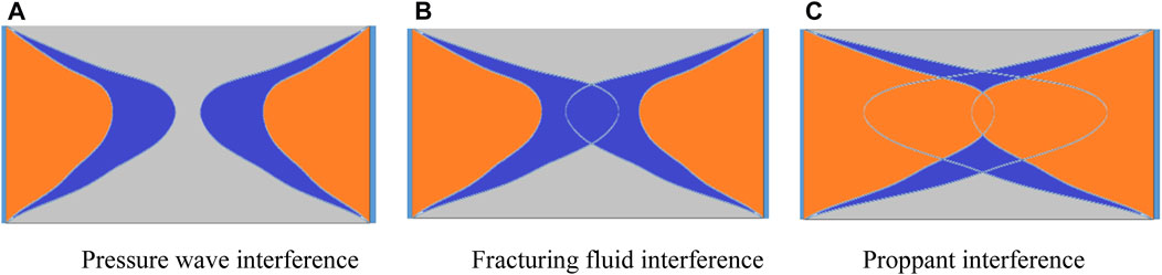
FIGURE 2. Three types of inter-well interference (Hou et al., 2022).
3 Numerical simulation method and program verification
3.1 The simulation method
The Displacement discontinuity method (DDM) is an approach employed for computing the static and dynamic responses of structures, primarily applied to solve complex nonlinear problems. This method is founded upon the finite element framework, where the domain is discretized into multiple non-continuous elements. Its primary objective is to enhance the precision of solutions, particularly for problems involving discontinuities or lack of smoothness. DDM is built upon the principles of continuum mechanics and involves subdividing fracture surfaces into numerous small sub-elements. It calculates the distribution of displacements, stresses, and strains within each sub-element to depict the behavior of fracture deformation and propagation more accurately. This discretization approach allows for a finer representation of deformation and stress distribution on the fracture surface. Additionally, the DDM method naturally handles multi-physics coupling problems and nonlinear issues, making it highly suitable for scenarios featuring discontinuities such as fractures and defects in the petroleum industry.
3.2 The verification of the developed program
3.2.1 The reliability of calculating the fracture aperture
Fracture aperture is a key parameter. The purpose of hydraulic fracturing is to create complex fractures with high conductivity. Fracture conductivity is determined by fracture aperture and fracture permeability. During hydraulic fracturing, the fracturing fluid is injected into the reservoir with high pressure. When the injection pressure is beyond the in-situ stresses, hydraulic fractures can be generated with an aperture. The fracture aperture determines the fracture conductivity and the value of the induced stresses. When the created fracture closes with a zero aperture, the fracture cannot contribute to the well production. The accurate calculation of the fracture aperture is of great value for the design of hydraulic fracturing. The analytical solution in Eq. 1 was applied to verify the reliability of the program. As shown in Figure 3, the half fracture length of a is set as 1 m, the in-fracture net pressure of Pnet is set as 2 MPa, Young’s modulus of E is set as 38 GPa, and the Poisson’s ratio of v is set as 0.27.
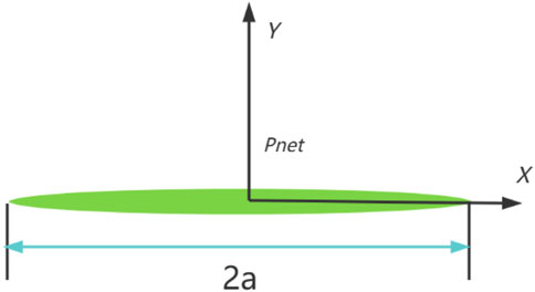
FIGURE 3. Schematic diagram of a linear fracture under internal pressure.
Figure 4 gives the calculation results of the fracture aperture based on the analytical solution and the developed program. The fracture width obtained based on DDM aligns well with that based on the analytical solution. Therefore, the developed program can be applied to simulate the fracture geometry.
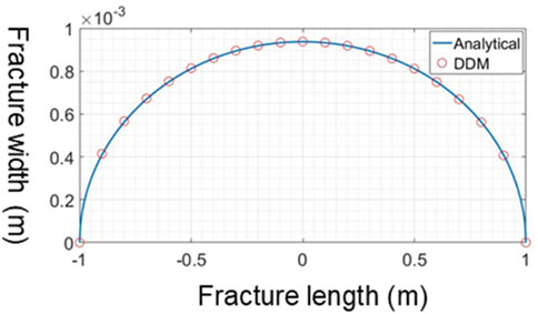
FIGURE 4. Fracture aperture comparison between the analytical solution and the developed program.
Where w is the fracture aperture, Pnet is the in-fracture net pressure, E is Young’s modulus, a is the half fracture length, and v is Poisson’s ratio.
3.3 Stress field verification
During hydraulic fracture propagation, the in-fracture fluid exerts pressure on the fracture surface and the rock around the fracture will be squeezed. In this way, the induced stresses will be generated and the spatial stress will be altered. The advantages of integral fracturing lie in fully utilizing the spatial stress field. The analytical solution is applied to verify the reliability of the developed program in calculating stress. Figure 5A and Figure 5B show the stress comparison between the analytical solution and the developed program in the x direction and the y direction, respectively., y denotes the distance between the target point and the fracture central point, a denotes the fracture half-length. The stress field from the developed program is in good agreement with that from the analytical solution. Therefore, the developed program can applied to calculate the stress field during integral fracturing.
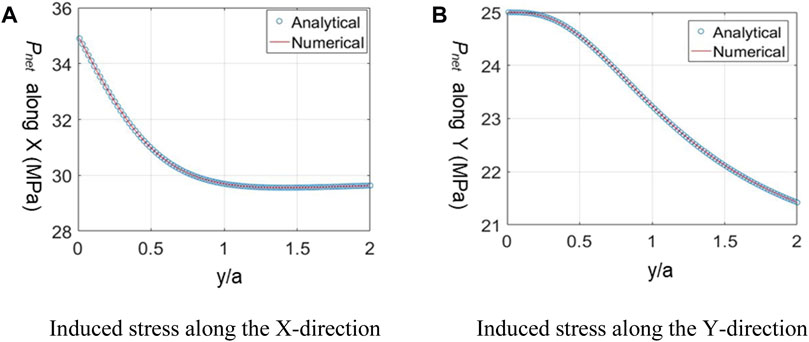
FIGURE 5. Stress comparison between the analytical solution and the developed program.
4 Numerical simulation results and analysis
This part firstly investigates the stress distribution induced by the close-spaced fractures within one fracturing stage. Secondly, this part systematically investigates the overall fracture geometry and the spatial stress distribution influenced by various factors during integral fracturing. The factors include the fracture half-length, fracturing sequence, fracture distribution mode, and in-fracture net pressure.
4.1 Stress distribution induced by close-spaced fractures
During hydraulic fracturing, the high-pressure injection fluid creates hydraulic fractures and the fracture surfaces compress the surrounding rocks. The rocks generate deformation and extra stresses. The induced stresses can be superposed to the in-situ stress field. The altered stress field can highly influence the overall fracture geometry and the stimulation effects. Therefore, it is crucial to understand the distribution of the induced stress field during integral fracturing. In this study, one fracturing stage with 3 perforation clusters was simulated to investigate the induced stress field. As shown in Figure 6A–D, the fracture spacing is set to as 10, 15, 20, and 25 m. Figure 6 gives the stress field and the overall fracture geometry based on the developed program. It shows that the fracture interference is strong with a small fracture space. The induced stress makes the side fracture propagate with a high diversion angle. There is a compressive stress region surrounding the fractures and a tensile stress region at the front of the fractures. The size of the region increases with fracture spacing. Stress reversal may occur at the region among multiple fractures and a complex fracture network can be generated. The size of the stress reversal region increases with fracture spacing. The region in front of hydraulic fractures is at a tensile state, the permeability of rock is high and reservoir fluid can smoothly flow into the fractures. The size of the tensile zone increases with fracture spacing. Therefore, both of the tensile region and the compressive region are beneficial for the development of resources. The direction of the minimum horizontal principal stress is along the X-direction and the direction of the maximum horizontal principal stress is along the Y-direction. The simple fracture geometry can be generated with a high difference between the two principal stresses. Hydraulic fractures should control the whole seepage zone along the horizontal wellbore. Moreover, the diversion angle of the side fracture decreases with fracture spacing. Proppant settlement tends to happen with a high diversion angle or a small fracture spacing. Therefore, fracture spacing should be optimized in consideration of the size of the stress reversal region, the size of the controlled seepage zone, and the risk of the proppant settlement.
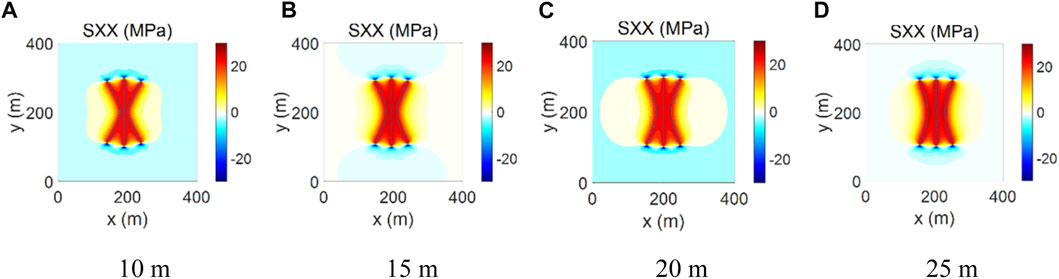
FIGURE 6. The stress distribution and fracture geometry with different fracture spacings.
4.2 The effect of half fracture length
For a given reservoir, fracture length can be controlled by designing the fluid injection rate, the fluid injection scale, and the proppant scale. Moreover, experts can inject the small size diverters to plug the fracture tips. In this way, the fracturing fluid cannot flow forward and the fracture will stop propagating. The fracture length significantly influences the size of the stress field. Shorter fractures lead to stress concentration, while longer fractures will weaken local stress. Therefore, it is particularly important to study the influence of fracture length on the evolution of the stress field. The well spacing is 300 m, and the in-fracture net pressure is 8 MPa. Based on the developed program, Figure 7A and Figure 7B simulate two cases with fracture half-lengths of 50 and 100 m, respectively. Gives the stress field and the fracture geometry. The red region represents the compressive region and the blue region represents the tensile region. Shearing fractures tend to be generated in the red region and tensile fractures tend to be generated in the blue regions. The fractures are more complex and the reservoir fluids can smoothly flow from the branch fractures into the main fractures. Moreover, there is a poorly stimulated region among the wells if the fracture half-length is too short. When the fracture half-length is 100 m, the size of the induced stress field increases, and pressure wave interference can be obtained in the fracture tip regions.

FIGURE 7. Stress field distribution with different half-fracture lengths.
4.3 The effect of fracturing sequence
The fracturing sequence indicates the fracturing order of the horizontal wells. A single well will be fractured from the first stage to the last stage continuously; For a well platform, several wells are fractured alternatively, stage by stage. The well spacing is set as 300 m, the in-fracture net pressure is set as 8 MPa and the fracture half-length is set as 100 m. Based on the developed program, two cases with different fracturing sequences are simulated. As show in Figure 8A, the sequential fracturing order indicates Well A, Well B, and Well C. As show in Figure 8A, the alternating fracturing order indicates Well A, Well C, and Well B. Figure 8 gives the stress field distribution and the overall fracture geometry. The stress compressive region is among multiple fractures and the tensile region is at the front of the fracture tips. Given the same fracture half-length and the fracture spacing, the fracturing sequence has a negligible effect on the stress field and the fracture geometry. However, for the fracturing stages along the same well, the adjacent stage has a high influence on the initiation and propagation of the hydraulic fractures. This effect is treated as inter-stage interference.
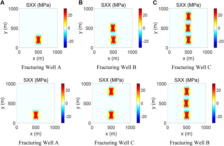
FIGURE 8. Stress field distribution with different fracturing sequences.
4.4 The effect of fracture distribution mode
Fracture distribution mode denotes whether the perforation clusters of different wells are in a straight line. There are two fracture distribution modes: the symmetrical fracture distribution and the staggered fracture distribution. Fractures of different wells will propagate in a line for the former case and propagate with a deviation in distance for the latter case. The well spacing is 300 m, and the in-fracture net pressure is 8 MPa. The fracture half-lengths are set as 50, 100, 150, and 200 m. Based on the developed program, two cases of different fracture distribution modes are simulated. Figures 9A–D, 10A–D give the stress distribution field and the overall fracture geometry under different fracture half-lengths. When the fracture half-length is 50 m, neither of the two distribution modes achieves the state of pressure wave interference. When the half-length of the fracture is 100 m, the pressure wave interference state can be realized by both kinds of distribution modes. When the fracture half-length is 150 m, symmetrical distribution mode results in liquid or proppant interferences between fractures, while pressure wave interference can still be observed under staggered distribution mode. When the fracture half-length is 200 m, the stress field and the overall fracture geometry have a negligible difference from that in the case with the fracture half-length of 150 m. The reason is the stresses are increased and the given in-fracture net pressure cannot propagate the hydraulic fracture. Therefore, the situation is unfavorable for well production. These observations highlight the influence of fracture half-length and distribution modes on the potential for interference or crosstalk during hydraulic fracturing operations.
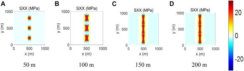
FIGURE 9. Stress field distribution of symmetrical fracture layout with different fracture half-lengths.
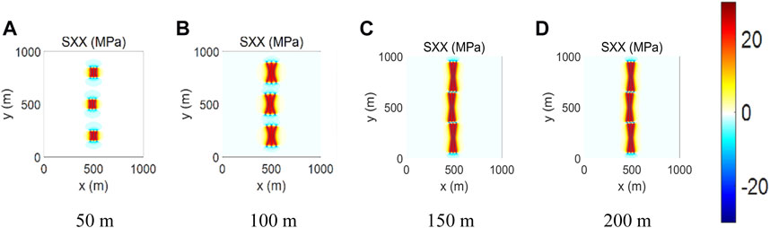
FIGURE 10. Stress field distribution of staggered fracture layout with different fracture half-lengths.
4.5 The effect of well-spacing
Well-spacing denotes the distance between the adjacent wells. The fracture half-length is set as 150 m, the in-fracture net pressure is set as 8 MPa, and two kinds of fracture distribution modes are considered. Based on the developed program, the cases of different well-spacings are simulated. The well-spacings are set as 200, 250, 300, and 350 m. Figures 11A–D, 12A–D give the stress distribution field and the overall fracture geometry under different well-spacing. Hydraulic fractures penetrate the adjacent fractures from the offset wells at the well-spacings of 200 and 250 m. When the well-spacing is 200 m in the case of the staggered distribution mode, hydraulic fractures propagate in the regions among the fractures. The fracture tips propagate with a deflection angle. In the case of symmetric fracture distribution, the middle fracture penetrates the fracture from the offset well, while the side fractures propagate with a diversion angle. In this way, fracturing interference hurts well production. When well-spacing is 250 m, the staggered distribution mode results in an even higher fracture diversion angle. When well-spacing is 300 m, the pressure wave interference can be obtained with the staggered distribution mode, while the fluid or the proppant interference will be obtained with the symmetric distribution mode. When the well-spacing is 350 m, both fracture distribution modes can generate pressure wave interference. It can be concluded that for well-spacing below 250 m, the staggered distribution mode can achieve better reservoir stimulation. An asymmetric fracture distribution mode is necessary to achieve effective reservoir improvement for well-spacing beyond 300 m.
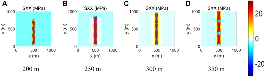
FIGURE 11. Stress field distribution of symmetrical fracture layout with different well spacings.

FIGURE 12. Stress field distribution of staggered fracture layout with different well spacings.
4.6 The effect of in-fracture net pressure
In-fracture net pressure denotes the fluid pressure minus the minimum horizontal principal stress. It highly influences the fracture aperture and the stress distribution. The in-fracture net pressure can be controlled by adjusting the fluid injection rate and the fluid viscosity. For formation with high permeability, it is difficult to enhance the in-fracture net pressure due to the fluid filtration. Experts can inject the filtrate reducer to plug the natural fracture and lower the fluid leak-off rate. The fracture half-length is set at 150 m and the well-spacing is set at 300 m. Only the staggered distribution mode is considered. Based on the developed program, the cases with different in-fracture net pressures are simulated. Figure 13 gives the stress distribution field and the overall fracture geometry. As shown in Figure 13A, it indicates that a higher in-fracture net pressure leads to a larger induced stress field area and facilitates achieving a more effective pressure wave interference effect. As shown in Figure 13B, when the in-fracture net pressure is 8 MPa, there is a blank region of the pressure wave interference among the fractures. When the in-fracture net pressure is 10 MPa, the pressure wave interference is desirable and the stimulation effect can be enhanced. Moreover, the compressive region among the fractures of the same well is more likely to generate shearing fractures. Well, production can be increased due to the mature stimulation effect.
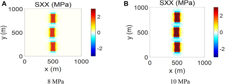
FIGURE 13. Stress field distribution with different in-fracture net pressures.
5 Discussion
5.1 Fracturing interference solution
During hydraulic fracturing, pressure wave interference is beneficial for well production while fluid interference or proppant interference can dramatically decrease well production. To obtain the pressure wave interference effects, the operation parameters of integral fracturing should be optimized and adjusted. Based on the simulation results, the following solutions can be applied to avoid the fluid or the proppant interference: 1) The parent wells should be pre-filled to improve the stress of the parent well and avoid the asymmetric fracture propagation of the child wells. 2) Active well prevention, that is, pumping the present wells while fracturing the new well, effectively weakens the interference of the child well on the parent well production. 3) Apply the temporary plugging and diverting fracturing method. It can achieve balanced stimulation within one fracturing stage. It can avoid the single “super fracture” burst into the fractures of the offset wells. 4) For far-field steering, the temporary plugging material (100 mesh quartz sand and 325 mesh silica powder) can be pumped into the fracture tip to bridge the fracture length. In this way, the fracture tips can be plugged and the fracture length can be controlled. It more likely to obtain the pressure wave interference with short fractures. 5) Reduce the stress barrier. The stress barrier can be formed by pressuring the well close to the parent well. It can avoid attracting the whole platform from the failure area of the parent well. Moreover, the interference can be significantly reduced through batch drilling and batch pressuring. For example, fracturing interference occurred between two adjacent wells. The interference had little impact on production after the integral fracturing of a 4-well platform.
5.2 Collaborative optimization of stress interference and production interference
The fracture half-length plays a pivotal role in determining the induced stress range and the degree of pressure wave interference. The fracturing sequence directly impacts the fracture network complexity and the stimulation volume in each fracturing stage. Additionally, variations in fracture length under different distribution modes can lead to distinct types of inter-well interference. It is necessary to consider the synergistic relationships among various fracturing operation parameters when fracturing the platform wells. It is crucial for promoting beneficial inter-well interference. This approach not only enhances overall stimulation effectiveness but also establishes favorable conditions for stable production stress. It can also prevent inter-well production interference during the later production stages. Experts can integrate the Petrel and CMG platforms to realize the collaborative optimization of integral fracturing. Petrel can establish the fine geological model in consideration of the reservoir heterogeneity. CMG can accurately simulate the fluid flow within the fractures and the rock matrix. Various parameters can be optimized at the same time by use of the intelligent search algorithm. Here is an example of optimizing the overall operation parameters. Figure 14 gives the optimization model. In this model, the fracture half-length, well-spacing, fracture distribution mode, and the in-fracture net pressure can be considered. Based on the intelligent search algorithm, these parameters can be optimized at the same time. It is a big difference from the single-factor analysis. The former can achieve the globally optimal result while the latter can just obtain the local optimal result. Through integral optimization, the pressure wave interference can be obtained with an optimal parameter combination of fracture half-length, well-spacing, fracture distribution mode, and in-fracture net pressure. The production potential of the platform wells can be fully excavated.
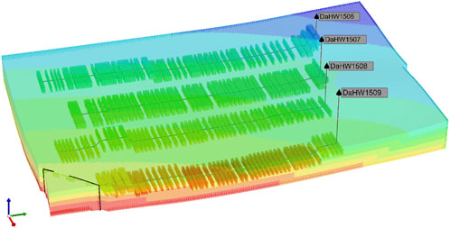
FIGURE 14. The optimization model of the overall operation parameter.
6 Conclusion
A simulation program for integral fracturing was developed based on the DDM and fracture mechanics theory. Systematic investigations were conducted to discover the impact of fracture half-length, fracturing sequence, fracture placement mode, well spacing, and in-fracture net fracture on stress field distribution and fracture geometry. The conclusions are as follows.
(1) Integral fracturing applies one-time well placement, one-time well completion, and 3D fracturing operation. It offers a dual advantage of efficiency improvement and cost reduction. This approach facilitates vertical multi-layer deployment and 3D development, ensuring the efficient extraction of unconventional oil and gas resources.
(2) Hydraulic fracturing involves the high-pressure injection of fluid, leading to the formation of a high-stress field on both sides of the fracture and a low-stress field in the fracture tip region. The high-stress field promotes the creation of a fracture zone, while the low-stress field favors the development of tensile fractures, significantly enhancing fluid permeability within the fracturing area.
(3) The effects of fracture half-length, well spacing, fracture distribution mode, fracturing sequence, and in-fracture net pressure work together. Collaborative optimization is necessary to avoid fluid/proppant and obtain pressure wave interference. Based on the simulation results, better stimulation effect and higher production can be obtained by setting the fracture half-length of 100 m, designing well spacing of 300m, applying the staggered fracture distribution mode, and controlling in-fracture net pressure of 10 MPa.
Data availability statement
The raw data supporting the conclusion of this article will be made available by the authors, without undue reservation.
Author contributions
BL: Writing–original draft. ZL: Writing–original draft. YL: Writing–original draft. JC: Writing–original draft. LZ: Writing–original draft. BW: Writing–original draft, Writing–review and editing.
Funding
The author(s) declare financial support was received for the research, authorship, and/or publication of this article. This work was funded by the National Natural Science Foundation of China (No. 52104011), the Natural Science Foundation of Xinjiang Uygur Autonomous Region (2022D01B77), and the Karamay Innovative Environment Construction Plan (Innovative talents) project (NO. 20232023hjcxrc0037).
Conflict of interest
Authors BL, ZL, YL, and JC were employed by PetroChina Xinjiang Oilfield Company.
The remaining authors declare that the research was conducted in the absence of any commercial or financial relationships that could be construed as a potential conflict of interest.
Publisher’s note
All claims expressed in this article are solely those of the authors and do not necessarily represent those of their affiliated organizations, or those of the publisher, the editors and the reviewers. Any product that may be evaluated in this article, or claim that may be made by its manufacturer, is not guaranteed or endorsed by the publisher.
References
Chen, J., Xu, Z., and Leung, J. Y. (2022). Analysis of fracture interference – coupling of flow and geomechanical computations with discrete fracture modeling using MRST. J. Petroleum Sci. Eng. 219, 111134. doi:10.1016/j.petrol.2022.111134
Chen, Z. M., Liao, X. W., and Zeng, L. B. (2020). Pressure transient analysis in the child well with complex fracture geometries and fracture hits by a semi-analytical model. J. Petroleum Sci. Eng. 191, 107119. doi:10.1016/j.petrol.2020.107119
Cong, Z., Li, Y., Liu, Y., and Xiao, Y. (2021). A new method for calculating the direction of fracture propagation by stress numerical search based on the displacement discontinuity method. Comput. Geotechnics 140, 104482. doi:10.1016/j.compgeo.2021.104482
Dong, X., and Ma, X. (2022). Influence of natural fractures on hydraulic fracture propagation behaviour. Eng. Fract. Mech., 276108932. doi:10.1016/j.engfracmech.2022.108932
Escobar, R. G., Mejia Sanchez, E. C., Deane, R., and Romanel, C. (2019). Xfem modeling of stress shadowing in multiple hydraulic fractures in multi-layered formations. J. Nat. Gas Sci. Eng. 70, 102950. doi:10.1016/j.jngse.2019.102950
Han, Z., Zeng, X., Wu, J., Chen, H., Li, W., and Yang, X. (2021). Phase-field modeling of interactions between double cracks on brittle fracture of Zircaloy-4 cladding. Comput. Mater. Sci. 197, 110565. doi:10.1016/j.commatsci.2021.110565
Hou, B., Zhang, Q., Liu, X., Pang, H., and Zeng, Y. (2022). Integration analysis of 3D fractures network reconstruction and frac hits response in shale wells. Energy 260, 124906. doi:10.1016/j.energy.2022.124906
Hu, M., Ge, H., Bai, J., Wang, X., Zhang, J., Shen, Y., et al. (2021). Variation of induced stress field during hydraulic fracture closure and its influence on subsequent fracture. Energy Rep. 7, 7785–7803. doi:10.1016/j.egyr.2021.10.105
Hu, M., Wang, X., Ge, H., Chen, L., Yao, Y., Shen, Y., et al. (2022). Balanced stress fracturing theory and its application in platform well fracturing during unconventional oil and gas development. Energy Rep. 8, 10705–10727. doi:10.1016/j.egyr.2022.08.214
Huang, L., Tan, J., Fu, H., Liu, J., Chen, X., Liao, X., et al. (2023). The non-plane initiation and propagation mechanism of multiple hydraulic fractures in tight reservoirs considering stress shadow effects. Eng. Fract. Mech. 292, 109570. doi:10.1016/j.engfracmech.2023.109570
Jaripatke, O. A., Barman, I., Ndungu, J. G., Schein, G. W., Flumerfelt, R. W., Burnett, N., et al. (2018). “Review of permian completion designs and results,” in Proceedings of the SPE Annual Technical Conference and Exhibition, Dallas, Texas, USA, September 2018.
Liu, Y., Zheng, X., Peng, X., Zhang, Y., Chen, H., and He, J. (2022). Influence of natural fractures on propagation of hydraulic fractures in tight reservoirs during hydraulic fracturing. Mar. Petroleum Geol., 138105505doi:10.1016/j.marpetgeo.2021.105505
Pankaj, P. (2018). “Characterizing well spacing, well stacking, and well completion optimization in the Permian Basin – an improved and efficient workflow using cloud based computing,” in Proceedings of the Unconventional Resources Technology Conference, Houston, Texas, USA, July 2018.
Pankaj, P., Shukla, P., Kavousi, P., and Carr, T. (2018). “Determining optimal well spacing in the Marcellus shale: a case study using an integrated workflow,” in Proceedings of the SPE Argentina Exploration and Production of Unconventional Resources Symposium, Neuquen, Argentina, August 2018.
Prieto, M., Aristizabal, J. A., Pradilla, D., Gómez, J. M., et al. (2022). Simultaneous numerical simulation of the hydraulic fractures geometry in multi-stage fracturing for horizontal shale gas wells. Comput. Geotechnics 140, 104482. doi:10.1016/j.jngse.2022.104567
Ren, L., Yu, Z., Zhao, J., Lin, R., Wu, J., Wu, J., et al. (2022). Hydraulic fractures simulation in non-uniform stress field of horizontal shale gas well. J. Petroleum Sci. Eng. 216, 110843. doi:10.1016/j.petrol.2022.110843
Saber, E., Qu, Q., Sarmadivaleh, M., Aminossadati, S. M., and Chen, Z. (2023). Propagation of multiple hydraulic fractures in a transversely isotropic shale formation. Int. J. Rock Mech. Min. Sci. 170, 105510. doi:10.1016/j.ijrmms.2023.105510
Saberhosseini, S. E., Ahangari, K., and Mohammadrezaei, H. (2019). Optimization of the horizontal-well multiple hydraulic fracturing operation in a low-permeability carbonate reservoir using fully coupled XFEM model. Int. J. Rock Mech. Min. Sci. 114, 33–45. doi:10.1016/j.ijrmms.2018.09.007
ShiqianQihongSen, X. F. W., Javadpour, F., and Li, Y. (2018). Optimization of multistage fractured horizontal well in tight oil based on embedded discrete fracture model. Comput. Chem. Eng. 117, 291–308. doi:10.1016/j.compchemeng.2018.06.015
Tang, H., Wang, S., Zhang, R., Li, S., Zhang, L., and Wu, Y. S. (2019). Analysis of stress interference among multiple hydraulic fractures using a fully three-dimensional displacement discontinuity method. J. Petroleum Sci. Eng. 179, 378–393. doi:10.1016/j.petrol.2019.04.050
Wang, L., Duan, K., Zhang, Q., Li, X., Jiang, R., and Zheng, Y. (2023a). Stress interference and interaction between two fractures during their propagation: insights from SCDA test and XFEM simulation. Int. J. Rock Mech. Min. Sci. 169, 105431. doi:10.1016/j.ijrmms.2023.105431
Wang, W., Zhang, G., Hu, C., Chen, L., and Zhao, C. (2023b). Generation mechanism and influencing factors of fracture networks during alternate fracturing in horizontal wells. Theor. Appl. Fract. Mech. 0167–8442. doi:10.1016/j.tafmec.2023.104082
Wang, Z., Yang, L., Gao, R., Xu, G., Liu, Z., Mo, S., et al. (2022). Numerical analysis of zipper fracturing using a non-planar 3D fracture model. Front. Earth Sci. 10, 808183. doi:10.3389/feart.2022.808183
Yang, C.-X., Yi, L.-P., Yang, Z.-Z., and Li, X.-G. (2022). Numerical investigation of the fracture network morphology in multi-cluster hydraulic fracturing of horizontal wells: a DDM-FVM study. J. Petroleum Sci. Eng. 215, 110723. doi:10.1016/j.petrol.2022.110723
Yoshioka, K., Mollaali, M., and Kolditz, O. (2021). Variational phase-field fracture modeling with interfaces. Comput. Methods Appl. Mech. Eng. 384, 113951. doi:10.1016/j.cma.2021.113951
Zhang, H., and Sheng, J. (2020). Optimization of horizontal well fracturing in shale gas reservoir based on stimulated reservoir volume. J. Petroleum Sci. Eng. 190, 107059. doi:10.1016/j.petrol.2020.107059
Zhang, J., Yu, H., Wang, Q., Lv, C., Liu, C., Shi, F., et al. (2022). Hydraulic fracture propagation at weak interfaces between contrasting layers in shale using XFEM with energy-based criterion. J. Nat. Gas Sci. Eng., 101104502. doi:10.1016/j.jngse.2022.104502
Zhang, Y., and Yang, D. (2021). Evaluation of transient pressure responses of a hydraulically fractured horizontal well in a tight reservoir with an arbitrary shape by considering stress-sensitive effect. J. Petroleum Sci. Eng. 202, 108518. doi:10.1016/j.petrol.2021.108518
Zhao, X., Jin, F., Liu, X., Zhang, Z., Cong, Z., Li, Z., et al. (2022). Numerical study of fracture dynamics in different shale fabric facies by integrating machine learning and 3-D lattice method: a case from Cangdong Sag, Bohai Bay basin, China. J. Petroleum Sci. Eng. 218, 110861. doi:10.1016/j.petrol.2022.110861
Keywords: integral fracturing, stress interference, fracture propagation geometry, the displacement discontinuity method, the fracture mechanics criteria
Citation: Lv B, Lv Z, Luo Y, Chen J, Zhang L and Wang B (2023) Investigation into the dynamic change pattern of the stress field during integral fracturing in deep reservoirs. Front. Energy Res. 11:1328789. doi: 10.3389/fenrg.2023.1328789
Received: 27 October 2023; Accepted: 20 November 2023;
Published: 06 December 2023.
Edited by:
Yan Peng, China University of Petroleum, ChinaReviewed by:
Daobing Wang, Beijing Institute of Petrochemical Technology, ChinaJie Wang, Greatwall Drilling Company (CNPC), China
Copyright © 2023 Lv, Lv, Luo, Chen, Zhang and Wang. This is an open-access article distributed under the terms of the Creative Commons Attribution License (CC BY). The use, distribution or reproduction in other forums is permitted, provided the original author(s) and the copyright owner(s) are credited and that the original publication in this journal is cited, in accordance with accepted academic practice. No use, distribution or reproduction is permitted which does not comply with these terms.
*Correspondence: Bo Wang, d2FuZ2JvQGN1cGsuZWR1LmNu