 Xinzhe Zhang1,2
 Xian Wang
 Guojie Zhang
- 1School of Aerospace Engineering, Zhengzhou University of Aeronautics, Zhengzhou, China
- 2Henan Key Laboratory of General Aviation Technology, Zhengzhou University of Aeronautics, Zhengzhou, China
- 3School of Mechanical and Power Engineering, Zhengzhou University, Zhengzhou, China
The aero-engine wide-chord hollow fan blade with a cavity stiffener structure can effectively reduce the weight and greatly increase the rotational speed. However, during the high-speed rotation process of the hollow fan, there is a strong coupling effect between the solid domain of the blade and the incoming air. This effect leads to a certain deformation of the rotor blade, which has a large impact on the structural strength of the blade. Aiming at the problem of the fluid–structure interaction in its operation, the finite-element method was used to simulate the two-layer structure of the TC4 titanium alloy wide-chord hollow fan blade. The centrifugal force and fluid–structure coupling effect were considered when carrying out the research on the structural mechanical characteristics of the blade. The results show that the maximum equivalent stress of the blade considering the fluid–structure coupling effect is 508 MPa at the rotational speed of 2,900 r/min, which is approximately 18% higher than the maximum stress when only the centrifugal force is considered. This phenomenon indicates that the effect of aerodynamic force on the blade stress cannot be ignored. The stress concentration area of the blade is located in the third stiffener from the leading edge and near the root of the blade, and the aerodynamic force has a more significant effect on the radial stress distribution of the blade. Further analysis of the equivalent stress distribution along the blade tip direction shows a trend of first increasing and then decreasing. The maximum equivalent stress appears at a distance of 30 mm up to the bottom of the stiffener.
1 Introduction
The rapid innovation of aerospace propulsion technology is prompting the development of aero-engine toward high loads and high thrust-to-weight ratios. An aero-engine fan blade, as the first-stage rotor, plays a very important role in the initial compression of incoming air and energy conversion (Shi et al., 2023). Therefore, due to the importance of the aero-engine fan blade, the aerospace industry has higher demands on the performance of the fan blade. Compared with the traditional aero-engine fan blade, the wide-chord hollow fan blade has the advantages of high efficiency, light weight, and strong resistance to external damage, which is widely used in turbofan engines with high rotational speed and high air intake (Zhang et al., 2012; Chen et al., 2018).
In recent years, with the gradual application of the wide-chord hollow fan blade on turbofan engines, new technical difficulties have begun to emerge. Due to the reduced mass of the blade, the wide-chord hollow fan blade is more prone to flutter under airflow impact (Zhang et al., 2018; Liu et al., 2019). The cavity stiffener structure also very easily causes blade vibration, and long-term high-stress working conditions will cause fatigue damage to the blade, even leading to blade fracture in severe cases, posing a threat to the flight safety of the aircraft (Wang et al., 2008). According to the statistics of aero-engine maintenance data (Rouleau et al., 2022), nearly one-third of turbofan engines need regular maintenance for fatigue deformation of the blade, which is mainly due to the vibration of the blade caused by the stress changes arising from the impact of the airflow. In addition, due to the thin thickness of the wide-chord hollow fan blade and coupled with the reduced mass, the stiffness will decrease accordingly, the response of external unsteady loads will become more and more significant, and the aerodynamic force effect on the blade cannot be ignored (Qu et al., 2015; Zhang and Fei, 2016). Therefore, the stress and structural strength characteristics of the wide-chord hollow fan blade under the aerodynamic force are of great significance for aero-engine fan blade design and maintenance (Wang et al., 2016).
Many researchers focus on the stress response and structural strength of the wide-chord hollow blade (Zhang et al., 2009; Zheng and Yang, 2011; Nikhamkin and Bolotov, 2014). Teichman and Tadros (1991) designed and carried out the experiments to record large blade deformations during bird impact and validated and calibrated the analytical models. They also described the analytical models and testing program and presented the dominant fan blade response and failure modes. Meguid et al. (2008) first studied the non-linear transient dynamic response of an artificial bird striking a rigid flat target, and then, they studied the impact behavior of an artificial bird impinging a flexible aero-engine fan blade. However, they only focused on the three most frequently used bird body configurations: straight-ended, hemispherical-ended cylinder, and ellipsoid. Hou and Chen (2015) analyzed the strength of a certain type of an aero-engine wide-chord hollow fan blade and verified that this type of fan blade meets the static strength design requirements and has a large safety reserve. Wang et al. (2018) calculated and verified the radial, circumferential, and axial displacement and stress of a titanium alloy wide-chord solid fan blade at working rotational speed and explored the mechanical response characteristics of the blade. Ji et al. (2013a) and Ji et al. (2013b) designed a wide-chord hollow fan blade, proposed two types of stiffener structure, checked their centrifugal load and bending moment load, and verified that the hollow blade of both structures can meet the design strength requirements. Anton (2021) constructed a large-bypass ratio hollow fan blade and analyzed the mechanical response characteristics of the blade skin and stiffener by numerical simulation. However, due to various objective factors such as experimental conditions, the above study only analyzed the mechanical characteristics of the fan blade without considering aerodynamic force and, thus, did not analyze the effect of the fluid–structure coupling interaction on the blade.
As researchers have realized the impact of aerodynamic force on the fan blade, aerodynamic simulation and experimental research on the wide-chord hollow fan blade have been conducted. Zeng et al. (2015), Pereira et al. (2021), and Martin (1990) presented a PW/WHAM impact analysis method, which coupled the WHAM program, a transient geometric and material non-linear plate finite-element analysis, a fluid finite-element projectile, and contact algorithms to form an advanced numerical calculation tool used to predict impact damage on structural components. Mao et al. (2007) studied the bird strike using the Lagrangian blade-bird formulations, and the bird was modeled as a fluid jet with a homogenized fluidic constitutive relation, also using the Brockman hydrodynamic model. Shi et al. (2011) compared the differences in mechanical performance parameters of a fan blade in coupled and uncoupled states by applying aerodynamic force on the blade structural mesh through two different data exchange methods, three-dimensional linear interpolation and constant volume transformation. Zhang et al. (2022) analyzed the fluid–structure coupling characteristics of a simplified fan rotor through aerodynamic numerical simulation and experimental measurement and compared the stress and deformation of the fan blade with only centrifugal force considered. They found that the stress on the surface of the blade after considering the effect of the fluid–structure coupling has a significant difference compared with only centrifugal force considered. Yi et al. (2020) calculated the deformation of a fan blade under aerodynamic force based on a fluid–structure coupling algorithm and applied the results to pre-deformation design of the blade. Vinha et al. (2020) constructed the governing equations of solid interaction through the strong-coupling and the weak-coupling methods and analyzed the stress and deformation of a certain aero-engine fan blade. All of the above studies have investigated the difference in the mechanical response of the solid blade under the influence of the fluid–structure coupling interaction effect. However, none of them has involved the cavity stiffener structure of the hollow fan blade, quantitatively analyzed the stress situation of the hollow blade stiffener, or explored the specific stress distribution of the weaker parts of the hollow fan blade (Chen and Liu, 2008; Li et al., 2023). However, the cavity stiffener structure is an extremely important part in the design of the hollow fan blade. Considering the influence of the fluid–structure coupling interaction effect, the strength analysis of the stiffener and the weak parts of the wide-chord hollow fan blade can make the results closer to the real situation and be more meaningful in engineering. At the same time, the research results can also provide theoretical reference for improving the aerodynamic performance and safe operation of the wide-chord hollow fan blade.
In order to investigate the influence of the fluid–structure coupling interaction effect on the mechanical properties of the wide-chord hollow fan blade, this paper will carry out numerical simulation of a two-layer cavity stiffener structure titanium alloy wide-chord hollow fan blade by ANSYS. The structural strength of this fan blade will be analyzed when aerodynamic force is considered, and the differences in blade stress between coupled and uncoupled states will be compared. The weak regions of this blade will be found, and the stress distribution in the weak parts of the blade, such as stiffener-skin, will be investigated.
2 Fluid–structure interaction method and blade finite-element model
2.1 Numerical method
In this paper, a unidirectional fluid–structure interaction method is used to analyze the effect of incoming air on the hollow fan blade, mainly because this method can greatly reduce the difficulty of model solving setup and improve the efficiency and stability of numerical calculation. The unidirectional fluid–structure interaction method mainly describes the node behaviors through the coupled fluid–structure governing equations and transfers various physical quantities from the fluid domain mesh to the solid domain mesh through the fluid–structure interfaces based on the principle of energy conservation. The basic governing equations for the fluid–structure coupling interaction can be formulated by Eq. (1), and as follows (Zhang et al., 2011):
where U = [x, y, z]T, U, P represent column vectors composed of pressure at each node in the whole domain. Each total coefficient matrix consists of the corresponding coefficient matrices of each element in the whole domain superimposed in a uniform manner and can be written as Eq. (2):
where Ae is the mass matrix, Be is the convection matrix, Ce is the pressure matrix, De is the depletion matrix, Ee is the area force matrix, Fe is the volume force matrix, Ge is the continuity matrix, and He is the boundary velocity matrix.
In the blade and air-coupled system explored in this paper, the air is compressible Newtonian fluid, and the mass conservation equation can be described as Eq. (3):
where ρ is the density of air, u is the velocity of air, and Sm is the air mass change of control volume, and this term is zero since the content studied in this paper does not involve phase transitions.
The motion law of the fan blade must follow Newton’s second law (Yan, 2020) as Eq. (4) shown:
where ρs is the blade material density, σs is the blade nodal Cauchy stress tensor, fs is the air volume force vector, and ds is the local acceleration vector in the blade region.
The fluid–structure coupling interaction should follow the basic conservation law that at the fluid–structure coupling interface, the variables of each node, such as stress (σ), displacement (d), heat (q), and temperature (T), should satisfy the equality or conservation between the fluid domain and the solid domain and can be described as follows (as Eq. (5) shown):
where the subscript f denotes the fluid, which, in this paper, refers to air. The subscript s denotes the solid, which, in this paper, refers to the fan blade.
In the numerical simulation analysis of this paper, the fluid turbulence model is set as the SST model. This model retains the highly sensitive k-ω model equation in the near-wall region, while the k-ε model equation is used in the fully developed region far from the wall, which has good applicability to the fluid domain with certain requirements for boundary layer simulation accuracy. The eddy-viscosity coefficient νt, k equation, and ω equation of the SST turbulence model can be described by Eqs 6–8 (Zhang et al., 2023a):
where F1 and F2 are mixed factor functions.
Based on the basic governing equation of fluid–structural coupling, the SST turbulence model is used to calculate the physical quantities in the air domain, and then, the flow field calculation results are transferred to the blade structural mesh through the fluid–structural coupling interface. Therefore, compared with the single k-ε model and the single k-ω model, a more accurate calculation result of aerodynamic force and centrifugal force coupling can be obtained, which can make the fluid–structural coupling interaction analysis of the wide-chord hollow fan blade more realistic and credible.
2.2 Construction of the wide-chord hollow fan blade and air domain finite-element model
In this paper, the fan blade of a turbofan engine shown in Figure 1A is taken as the study object (Yan, 2020), and its 3D solid model was constructed in CATIA. The fan blade is a two-layer cavity containing four stiffener structures. The blade is approximately 600 mm high and 210 mm wide, the twist angle is 60°, and the skin and stiffener are 2 mm thick. According to current blade manufacturing process technology, a very smooth structural transition can be achieved at the blade body and the blade rabbet; thus, the presence or absence of the transition zone has little impact on the results of the whole blade vibration characteristic analysis (Kou et al., 2016; Zhang et al., 2023b). Therefore, this paper simplifies the blade geometric model to achieve a high-quality mesh in the smooth transition zone between the blade body and the blade rabbet. The 3D solid model of the blade is obtained from a set of cross-section curves swept and then by Boolean operation, as shown in Figures 1B, C.
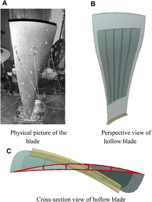
FIGURE 1. Two-layer cavity stiffener fan blade structure.
The 3D solid model of the fan blade is imported into workbench for meshing. Due to the complex geometry of the internal cavity and stiffener of the blade, the tetrahedral Solid 186 element type with more control nodes is selected for meshing the blade model (Zhang et al., 2023). For the Solid 186 element type, each element is defined by 20 nodes, and each node has three degrees of freedom for translation along the X-, Y-, and Z-direction. In addition, this element type can also have arbitrary spatial anisotropy and hyperelasticity, with the ability to large deformation and strain. The finite-element computational model and mesh of the wide-chord hollow fan blade are shown in Figure 2.
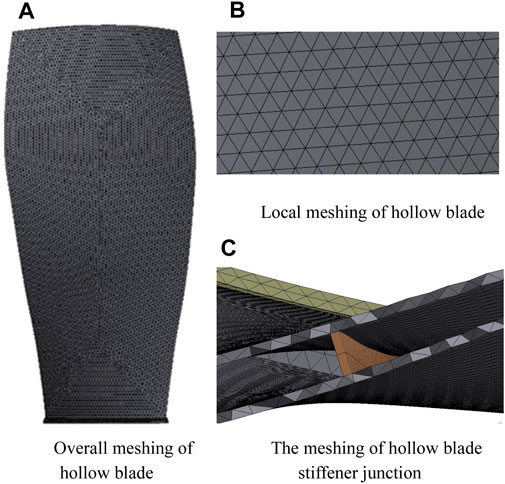
FIGURE 2. Meshing of the hollow fan blade.
In order to facilitate the observation and analysis of the mechanical response of the blade stiffener, this paper divides the stiffener and skin of the hollow blade into two parts and then connects them as a whole for analysis. In the actual production of the blade, the stiffener is welded to the blade skin, so the normal and tangential directions of the contact surface between the stiffener and the skin are not allowed to separate. Furthermore, the augmentation Lagrange contact algorithm is used for solving calculation to reduce computational time. The parameters related to Ti-6Al-4V titanium alloy material used for the wide-chord hollow fan blade are shown in Table 1.
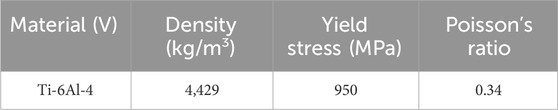
TABLE 1. Blade material parameters.
When setting the boundary conditions for the blade, considering that the radius of the blade disk is approximately 300 mm, the action point for applying angular velocity at all nodes of the blade is chosen to be 300 mm directly below the bottom surface of the blade. A clamped supported constraint is set on the action point, and full constraints are applied to the other degrees of freedom except RX so that the blade rotates around the X-axis.
To simulate the intake situation at the circular inlet of the turbofan engine, three fan-shaped bodies are constructed to form the flow field of a whole single fan blade. The blade tip is 8 mm away from the top of the flow field, and the air flowed in from the left inflow and out from the right outflow. Due to the regular geometry of the flow field, a hexahedral mesh is selected to meshing the flow field, and the mesh direction is aligned with the airflow direction as much as possible. The thickness of the first layer of the mesh is set to be 1 × 10⁻³ mm to meet the requirement of the mesh size value Y+ for the computational accuracy of the SST turbulence model (Zhang et al., 2024b). The finite-element calculation model and the mesh of the air flow field are shown in Figure 3.
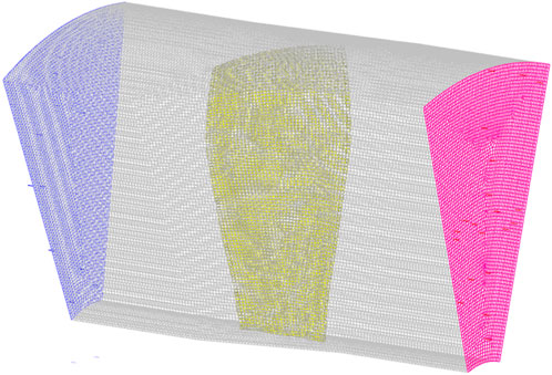
FIGURE 3. Finite-element calculation model of flow field.
Boundary conditions are set for the air flow field, which are the inlet of the flow field for flow control and the outlet for pressure control, and the rest of the boundary parameters are shown in Table 2.
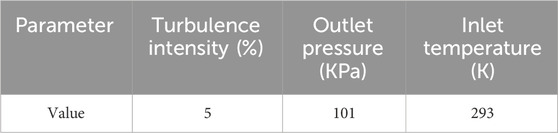
TABLE 2. Flow field boundary conditions.
2.3 Validation of mesh independence for the computational model
To determine the most reasonable mesh size in the numerical calculation, this study first conducts the mesh independence verification. The maximum stress of a certain blade mesh node at 2,900 r/min is set as the target solution, the other boundary conditions are kept consistent, and the mesh size is gradually reduced. When the mesh size is reduced from 20 mm to 3 mm, the target solution converged to approximately 433 MPa, as shown in Figure 4, and the computation time increased sharply when the mesh size is reduced from 4 mm to 3 mm, so 4 mm is selected as the mesh size. The numbers of the element and node after division are 90,536 and 172,099, respectively.
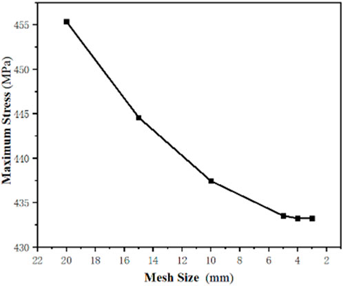
FIGURE 4. Maximum stress of the blade corresponding to different mesh sizes at 2900 r/min.
Then, the mesh independence verification of the flow field is conducted to determine the most reasonable mesh size for the flow field. The maximum aerodynamic force on the fan blade surface at an air flow rate of 35 kg/s is set as the target solution, the other boundary conditions are kept consistent, and the mesh size is gradually reduced. When the mesh size decreases from 15 mm to 7 mm, the target solution converged to 1.31 × 10⁵ Pa, as shown in Figure 5, and the computation time increases abruptly if the mesh size continues to be reduced, so the mesh size of the flow field is determined to be 7 mm. The numbers of the element and node after division are 535,854 and 501,037, respectively.
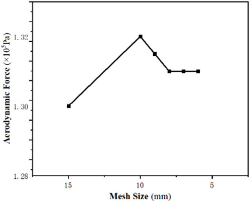
FIGURE 5. Maximum aerodynamic force on the blade surface for different mesh sizes at an air mass flow rate of 35 kg/s.
3 Results and discussion
3.1 Frequency margin analysis of the hollow fan blade
The hollow fan blade is subjected to various forms of excitation force under different working conditions. If the excitation force frequency is equal to or an integer multiple of the hollow fan blade natural frequency, the blade will resonate. At this time, a small external excitation can cause significant deformation of the blade, causing a sharp stress increase in the internal structure of the blade and easily leading to the blade fatigue fracture. The aero-engine fan blade operates for a long time during idle speed period, cruise speed period, and maximum takeoff speed period. In order to ensure the normal operation of the blade during these periods, the aero-engine fan blade design requires a margin of 10%–20% between the blade excitation force frequency and the blade natural frequency (Yang et al., 2018). The formula of external excitation force frequency can be described as follows (as Eq. (9) shown):
where K is the blade structural harmonic coefficient, which can be taken as n times the blade rotational speed (K = 1, 2, ., n), the magnitude of K value depends on the type of excitation force, and N is the aero-engine rotational speed.
The Campbell diagram describes the variation of blade natural frequency and external excitation force frequency with rotational speed and can be used to find the rotational speed at which the blade resonates (Tian et al., 2022). In this paper, K = 56 and K = 32 are taken to represent the high-frequency excitation force formed by the number of outlet guide blades and the difference between the number of guide blades and rotor blades, and the low-frequency excitation force is represented by K = 1, 2, 3, 4, and 5 (Kou et al., 2014). The Campbell diagram of the wide-chord hollow fan blade is shown in Figure 6.
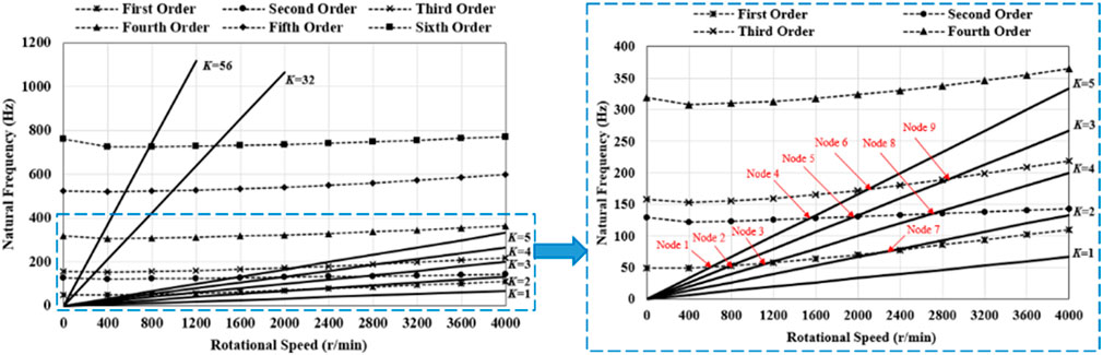
FIGURE 6. Campbell diagram of the wide-chord hollow fan blade.
The resonance point is the intersection of the positive proportion ray of K times the excitation force frequency and the natural frequency plot line. As the low-order excitation force is very harmful to the longer blade, and the lower the frequency, the more significant effect on the fan blade. Therefore, in this paper, the influence of the low-frequency excitation force on blade vibration characteristics is mainly considered. There are nine intersections in the first three natural frequencies, which are the intersection of the excitation force frequency at K = 2 with the second natural frequency, the intersection of the excitation force frequency at K = 3 with the first and second natural frequencies, the intersection of the excitation force frequency at K = 4 with the first, second, and third natural frequencies, and the intersection of the excitation force frequency at K = 5 with the first, second, and third natural frequencies.
Therefore, when the rotational speed of the turbofan engine is accelerated from 0 r/min to 4,000 r/min, it passes through nine resonance points at 600 r/min (node 1), 800 r/min (node 2), 1,100 r/min (node 3), 1,500 r/min (node 4), 1950 r/min (node 5), 2,150 r/min (node 6), 2,300 r/min (node 7), 2,700 r/min (node 8), and 2,850 r/min (node 9). When the fan blades work at these nine resonance points for a long time, a resonance phenomenon will occur, even creating danger. In order to avoid the resonance points during blade operation and to find a reasonable working range, it is necessary to further calculate the resonance frequency margin of the blade. The resonance frequency margin of the blade can be calculated by Eq. (10):
where fmd is the natural frequency of the mth-order mode at working rotational speed and fmi and fmi+1 are the corresponding frequencies of Ki and Ki+1 at working rotational speed, respectively.
According to Eq. 10, the first- to sixth-order frequency margins of the blade at rotational speed from 0 r/min to 4,000 r/min are shown in Figure 7. It can be seen that the first-order frequency margin is less than 10% at rotational speed from 1800 r/min to 2,900 r/min, and the first-order frequency margin is also more than 10% at rotational speed above 2,900 r/min. The second-order frequency margin is more than 10% at rotational speed from 2,900 r/min to 3,800 r/min. The third- to sixth-order modes of the blade from 1,200 r/min to 2,800 r/min have frequency margins approximately equal to 0. The turbofan engine inevitably passes through the resonance point when accelerating, but cannot stay at the resonance rotational speed for a long time. For the fan blade, the lower the modal order, the greater the vibration energy and the most dangerous the vibration generated. So, the engineering is most concerned about the frequency margin of the first three order modes. Generally, only the margin of the first three orders is considered, and the first- and second-order frequency margins are required to be greater than 10% (Yang et al., 2007).
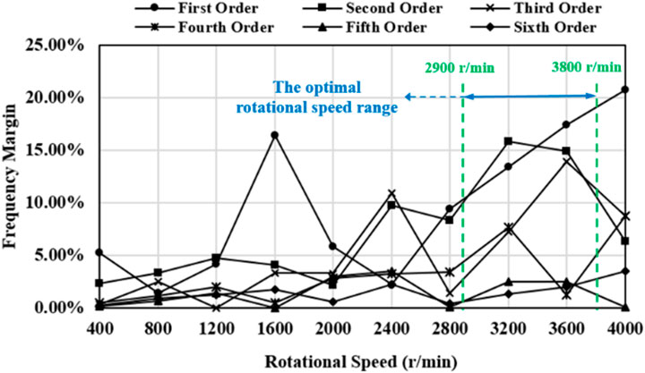
FIGURE 7. Frequency margin of the blade at each order from 0 r/min to 4,000 r/min.
The frequency margin of the blade at each order from 0 r/min to 4,000 r/min is shown in Figure 7. When the fan blade works at rotational speed from 2,900 r/min to 3,800 r/min, the frequency margins of the first and second orders are above 10%, the frequency margin of the third order is not less than 5%, and the other higher-order frequency margins are relatively low, fluctuating approximately 5%. Due to the lower energy generated by higher-order vibrations, the frequency margins of the fourth-, fifth-, and sixth-order vibrations are not considered. Therefore, the blade can quickly accelerate to 2,900 r/min, pass through the low-order resonance point, and then, work in the range of rotational speed from 2,900 r/min to 3,800 r/min, which is the optimal rotational speed range.
Therefore, in the subsequent research of this paper, the rotational speed of the fan blade is set at 2,900 r/min. Because at this rotational speed, the hollow fan blade is able to operate at a good frequency margin to ensure the safety and stability of the turbofan engine.
3.2 Static strength characteristics of the fan blade
When the blade operates under the normal operating conditions, it will be subjected to various loads and structural constraints, mainly due to its own centrifugal force. After a long time of operation, the mechanical properties and performance of the blade will be reduced, which may even lead to blade fracture in serious cases. Therefore, this paper first analyzes the response characteristics of the blade when it is only subjected to centrifugal force and then carries out the fluid–structural coupling analysis of the fan blade on this basis. Considering that the fan blade has a good frequency margin at 2900 r/min, the strength characteristics of the blade at this rotational speed are analyzed. After calculation, the equivalent stress distribution of the blade skin and stiffener at 2,900 r/min is shown in Figure 8.
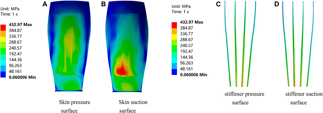
FIGURE 8. Stress distribution of the fan blade skin and stiffener at 2900 r/min.
As shown in Figures 8A, B, when the blade rotational speed is 2,900 r/min, the maximum equivalent stress of the hollow fan blade is distributed in the suction surface near the skin of the blade root, which reaches 433 MPa. As shown in Figures 8C, D, the maximum equivalent stress of the stiffener is distributed in the root of the blade both in the suction surface and the pressure surface, and the part in contact with the inner surface of the skin is subjected to the maximum equivalent stress, which reaches 408 MPa.
3.3 Analysis of the aerodynamic characteristics of the fan blade
As the first-stage rotor of the turbofan engine, the fan blades are subjected to not only their own centrifugal force but also other loads, mainly composed of aerodynamic force. When the fan blades are running, the air flow rate through a single blade can reach 35 kg/s, and the influence of aerodynamic force on the blades cannot be ignored. Therefore, it is particularly important to analyze and study the distribution of aerodynamic force on the blade surface and its impact on the blades. The distribution of aerodynamic force on the blade when the air flow rate is 35 kg/s is shown in Figure 9.
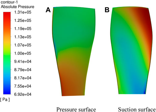
FIGURE 9. Aerodynamic distribution on the outer surface of the fan blade.
From Figure 9A, it can be seen that when air impacts the blade, the geometric shape of the blade root on the pressure surface is concave, which leads to a larger volume of the meridional air at that location and, therefore, receives a larger aerodynamic force of 1.31 × 10⁵ Pa. In contrast, the tip of the blade, due to the blade’s twisted geometrical shape, turns its back to the incoming direction and, therefore, receives a smaller aerodynamic force of 6.92 × 10⁴ Pa. Figure 9B shows that due to the large torsion angle of the blade, the leading edge of the suction surface is facing the direction of the incoming flow, resulting in the maximum aerodynamic force on the leading edge of the suction surface, reaching 1.31 × 10⁵ Pa. The aerodynamic force on the middle part of the suction surface blade is less due to the convex geometry, resulting in the fast air flow speed in this place, so the aerodynamic force on the middle part of the suction surface blade is smaller, which is only approximately 8.17 × 10⁴ Pa. Applying the aerodynamic force on the outer surface of the blade to the structural mesh of the fan blade, the stress distribution of the blade under only aerodynamic force was obtained, as shown in Figure 10.
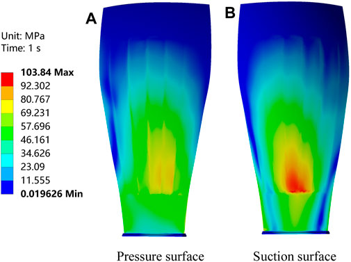
FIGURE 10. Blade stress distribution subjected to aerodynamic forces only.
From Figures 10A, B, it can be seen that when the fan blade is only subjected to the aerodynamic force, the maximum equivalent stress is distributed on the suction surface near the skin of the blade root, and the maximum value reaches 103 MPa. The distribution of the equivalent stress of the stiffener is also consistent with that when only the centrifugal force is considered; whether it is in the suction surface or in the pressure surface, the maximum equivalent stress of the stiffener is distributed in the root of the blade, and the maximum value reaches 100 MPa.
In this paper, the mechanical response of the fan blade is considered when centrifugal force and aerodynamic force are separately affected, but the loads on the fan blade during operation are usually the combined effect of the two superimposed. Therefore, further centrifugal force and aerodynamic force coupling analyses of the fan blade are required.
3.4 Mechanical response of the fan blade under the fluid–structure coupling interaction effect
The aerodynamic force calculation is carried out, and then, the aerodynamic force is applied to the structural mesh of the fan blade by using the numerical interpolation method. The centrifugal force analysis is carried out by using the fluid–structure coupling algorithm, and the mechanical response of the fan blade under centrifugal force and aerodynamic force coupling can be obtained by synthesizing the forces. Keeping the air flow rate as 35 kg/s, when the blade rotational speed is 2,900 r/min, the equivalent stress distribution of the fan blade in the uncoupled and coupled cases is shown in Figure 11.
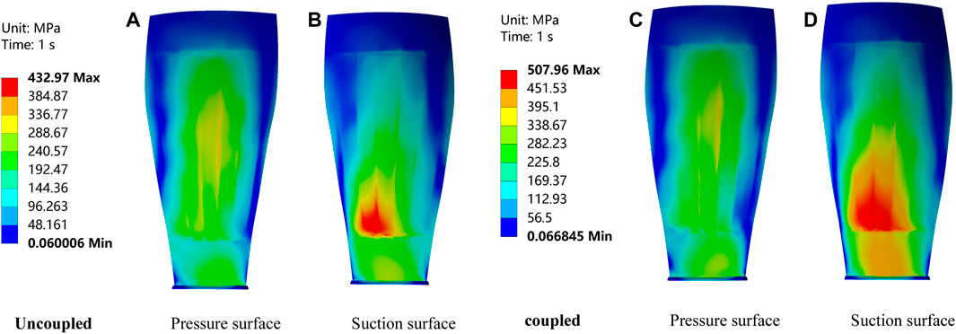
FIGURE 11. Comparison of blade equivalent stresses in uncoupled and coupled states.
From Figures 11A–D, it can be seen that the relative distribution of equivalent stresses on the pressure surface and suction surface of the blade after considering the aerodynamic forces is roughly similar to those when only the centrifugal force is considered, but the maximum equivalent stress reaches 508 MPa, which is approximately 18% higher than that when only the centrifugal force is considered. In addition, the stress values on the suction surface are substantially increased along both radial and axial directions. This indicates that the effect of the aerodynamic force is relatively significant for the overall stress value and has an undeniable contribution.
3.5 Mechanical response of the fan blade stiffener under the fluid–structure coupling interaction effect
The overall mechanical response characteristics of the wide-chord hollow fan blade considering aerodynamic force are explored. However, the stiffener–skin joint of the wide-chord hollow fan blade is the weaker part of the whole blade; so, a more detailed stress analysis of the stiffener and the stiffener–skin joint is needed.
The fan blade has four stiffeners, regardless of the centrifugal force alone, aerodynamic force alone, or the two coupled; the leading edge of the third stiffener near the root of the blade is always subjected to the largest equivalent stress, so the stiffener root stresses are discussed in different directions, as shown in Figure 12. The axial, circumferential, and radial stress distribution of the stiffener in coupled and uncoupled states are shown in Figure 13.
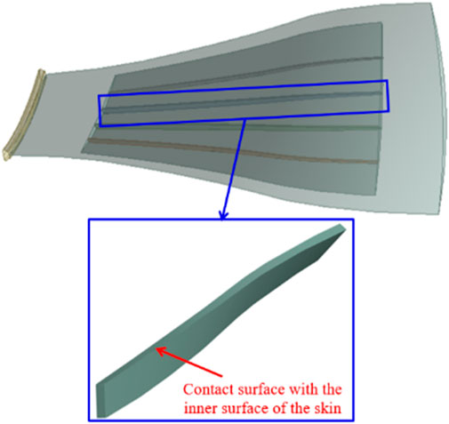
FIGURE 12. Location of the weak stiffener.
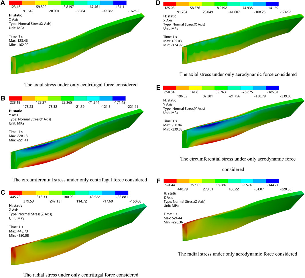
FIGURE 13. Axial, circumferential, and radial stress distribution of the stiffener when only centrifugal force and aerodynamic force are considered.
From Figures 13A–C, it can be seen that when only the centrifugal force is considered, the axial, circumferential, and radial stresses of the stiffener are 123 MPa, 228 MPa, and 446 MPa, respectively. As shown in Figures 13D–F, after considering the aerodynamic force, the stresses of the stiffener in each direction are increased as follows: the axial stress is increased approximately 1.2%, the circumferential stress is increased approximately 9%, and the radial stress is increased approximately 18%. This indicates that the aerodynamic force has a more significant impact on radial stress than other directional stresses and has the largest proportion in the increment of equivalent stress. Therefore, under the impact of some extreme external loads, such as bird and sand impact, the results obtained by considering high-flow aerodynamic force are likely to differ significantly from those without considering the aerodynamic force.
In order to further investigate the mechanical response of the stiffener–skin contact area, it is necessary to analyze the radial stress distribution of the joint area between the stiffener and the skin and compare the difference when it is subjected to aerodynamic force. The bottom of the stiffener is selected as the reference point, and the distance between the reference point and the bottom of the stiffener is 0 mm. On the common edge between the stiffener and the skin, several mesh nodes are sequentially arranged along the radial direction, as shown in Figure 14, and these nodes are located in the area of high stress at the contact area between the stiffener and the skin. To avoid discontinuity caused by singular points in the finite-element algorithm and the effect on the result analysis, the first node that spans from the solid part to the cavity part is removed. After obtaining the equivalent stress values for each node, the stress distribution along the radial direction and the percentage difference of the shared nodes considering only centrifugal force and fluid–structure interaction are shown in Figure 14. As shown in Figure 15, difference represents the percentage difference, ORI represents only centrifugal force, and FSI represents the fluid–structure interaction.
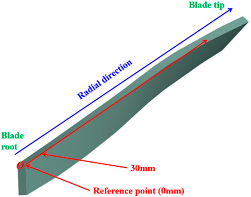
FIGURE 14. Common area of the stiffener and skin.
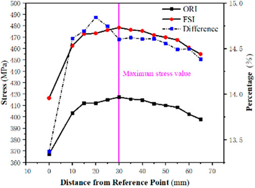
FIGURE 15. Radial stress distribution of the stiffener and skin shared nodes considering only centrifugal force and the fluid–structure interaction.
As can be seen from Figure 15, regardless of whether the influence of the aerodynamic force is considered, the equivalent stress at this point is relatively low due to the fact that the reference node is shared with the solid part. After that, the node equivalent force values begin to change gently, showing a trend of increasing and then decreasing, which is caused by the change in radial section centroid moment due to the complex structure of the hollow fan blade. At a distance of 30 mm from the bottom of the stiffener, the equivalent stresses in both cases reached their maximum values, reaching 418 MPa and 479 MPa. This indicates that the thickness of the stiffener at the root of the blade should be increased appropriately when designing the hollow fan blade in order to increase its load-resisting capacity. In addition, Figure 15 shows that as the distance between the node and the root of the stiffener increases, the incremental distribution of the equivalent stress when considering aerodynamic force is more uniform than that when only the centrifugal force is considered, which are all kept in the range of 14.5%–15% and are the most contributed by the increase in the radial force.
4 Conclusion
In this paper, the structural strength analysis of the turbofan engine wide-chord hollow fan blade under the effect of the fluid–structure coupling interaction is carried out. The results will have positive significance for the efficient aerodynamic performance design and structural lightweight optimization design of the wide-chord hollow fan blade. The conclusions are given as follows:
(1) The wide-chord hollow fan blade studied in this paper has a good resonance margin when the rotational speed is set from 2,900 r/min to 3,800 r/min, the frequency margins of the first and second orders are above 10%, and the frequency margin of the third order is not less than 5%. Moreover, this rotational speed range is the optimal working condition for the wide-chord hollow fan blade.
(2) When only considering centrifugal force load, the maximum equivalent stress of the hollow fan blade is distributed on the suction surface of skin near the root of the blade. The maximum equivalent stress of the stiffener is distributed at the root of the blade on both the suction surface and pressure surface, and the part in contact with the inner surface of the skin is subjected to the maximum equivalent stress.
(3) After considering the aerodynamic force, the distribution of equivalent stress on the blade is almost consistent with that when only the centrifugal force is considered, but the maximum equivalent stress increment can be up to 18% compared with that when only the centrifugal force is considered, and the impact of radial force is the most significant.
(4) The weak area of the fan blade is located in the third stiffener from the leading edge and near the root of the blade. After collecting enough analysis of the equivalent stress distribution along the radial direction of the blade stiffener–skin contact area, it can be seen that the overall equivalent stress trend is first increasing and then decreasing. The location of the maximum equivalent stress is approximately 30 mm from the bottom of the stiffener.
Data availability statement
The raw data supporting the conclusion of this article will be made available by the authors, without undue reservation.
Author contributions
XZ: conceptualization, methodology, software, and writing–original draft. XW: conceptualization, investigation, writing–original draft, and writing–review and editing. GL: data curation, writing–original draft, and writing–review and editing. YZ: formal analysis, writing–original draft, and writing–review and editing. GZ: project administration, supervision, writing–original draft, and writing–review and editing.
Funding
The authors declare that no financial support was received for the research, authorship, and/or publication of this article.
Acknowledgments
The authors are grateful for the financial support provided by the National Natural Science Foundation of China (52206059), the Science and Technology R&D Program of Henan Province (222102240028 and 232102230046), the Foundation of Henan Key Laboratory of General Aviation Technology (ZHKF-230202), and the Scientific Research Team Plan of Zhengzhou University of Aeronautics (23ZHTD01010).
Conflict of interest
The authors declare that the research was conducted in the absence of any commercial or financial relationships that could be construed as a potential conflict of interest.
Publisher’s note
All claims expressed in this article are solely those of the authors and do not necessarily represent those of their affiliated organizations, or those of the publisher, the editors, and the reviewers. Any product that may be evaluated in this article, or claim that may be made by its manufacturer, is not guaranteed or endorsed by the publisher.
References
Anton, S. (2021). 3D optimization of the hollow fan blade internal structure. J. Phys. Conf. Ser. 1891 (1), 012015. doi:10.1088/1742-6596/1891/1/012015
Chen, G., Wang, Y., Wang, Z., Zhu, R., Yang, H., and Luo, Z. (2018). Analysis of C5 palsy in cervical myelopathy with massive anterior compression following laminoplasty. Aerosp. Power 13 (05), 26–30. doi:10.1186/s13018-018-0715-3
Chen, M. Z., and Liu, B. J. (2008). Fan/compressor aero design technology for high bypass ratio turbofan. Acta Aeronautica Astronautica Sinica 29 (3), 513–526.
Hou, J. D., and Chen, S. X. (2015). Stress analysis of wide-chord fan blade from an aero engine. Aeronaut. Comput. Tech. 45 (02), 10–12.
Ji, F. S., Ding, Q., and Li, H. L. (2013a). Design and analysis of hollow wide-chord fan blade with two-layers and three-layers plate. Aeroengine 39 (02), 49–51+56.
Ji, F. S., Ding, Q., and Li, H. L. (2013b). Design and analysis of hollow fan blade structure. Aeroengine 39 (04), 42–44+66.
Kou, H. J., Fu, X., and Zhang, J. H. (2016). Stress and strength analysis of fan blades for a turbofan engine. China Sci. 11 (22), 2561–2567.
Kou, H. J., Zhang, J. H., and Lin, J. W. (2014). Aero-engine fan blade vibration characteristic analysis. J. Xi'an Jiaot. Univ. 48 (11), 109–114.
Li, C., Lang, L. H., and Sardar, M. I. (2023). Review on manufacture of aeroengine wide chord hollow fan blade. J. Aerosp. Power 38 (11), 2675–2687.
Liu, J., Zhong, D. D., Li, Y. L., Tang, Z., Gao, X., Zhang, Z., et al. (2019). Numerical simulation and test on damage of rotary engine blades impacted by bird. Int. J. Crashworthiness 24 (1), 106–120. doi:10.1080/13588265.2018.1452548
Liu, Z. Y. (2019). Study on impact dynamic responses of aero engine fan blade after bird striking[D]. Tianjin: Tianjin University, 20–21.
Mao, R. H., Meguid, S. A., and Ng, T. Y. (2007). Finite element modeling of a bird striking an engine fan blade. J. Aircr. 44 (2), 583–596. doi:10.2514/1.24568
Martin, N. F. (1990). Nonlinear finite-element analysis to predict fan-blade damage due to soft-body impact. J. Propuls. Power 6 (4), 445–450. doi:10.2514/3.25455
Meguid, S. A., Mao, R. H., and Ng, T. Y. (2008). FE analysis of geometry effects of an artificial bird striking an aeroengine fan blade. Int. J. Impact Eng. 35 (6), 487–498. doi:10.1016/j.ijimpeng.2007.04.008
Nikhamkin, M., and Bolotov, B. (2014). Experimental and finite element analysis of natural modes and frequencies of hollow fan blades. Mater. Sci. Mech. Eng. 467, 306–311. doi:10.4028/www.scientific.net/amm.467.306
Pereira, M., Ravelet, F., Azzouz, K., Azzam, T., Oualli, H., Kouidri, S., et al. (2021). Improved aerodynamics of a hollow-blade axial flow fan by controlling the leakage flow rate by air injection at the rotating shroud. Entropy 23 (7), 877. doi:10.3390/e23070877
Qu, H. C., Huang, Y. Q., and Wang, T. (2015). Modality and resonance analysis of civil aero-engine fan blade. J. Civ. Aviat. Univ. China 33 (06), 13–16.
Rouleau, L., De, S. O., and De, J. F. (2022). Vibration prediction of rotating composite fan blades comprising viscoelastic damping treatments. J. Sound Vib. 536, 117135. doi:10.1016/j.jsv.2022.117135
Shi, L., Guo, S. H., Yu, P., Zhang, X., and Xiong, J. (2023). A review on leading-edge erosion morphology and performance degradation of aero-engine fan and compressor blades. Energies 16 (7), 3068. doi:10.3390/en16073068
Shi, Y. Q., Wang, Q. Q., and Yang, Q. Z. (2011). Analysis of fluid-structure coupling characteristics in fan/compressor rotor. Comput. Simul. 28 (07), 115–119.
Teichman, H. C., and Tadros, R. N. (1991). Analytical and experimental simulation of fan blade behavior and damage under bird impact. J. Eng. Gas Turbines Power 113 (4), 582–594. doi:10.1115/1.2906281
Tian, S., Wu, Y. H., and Jia, Z. T. (2022). Analysis of resonance margin of aero⁃engine turbine blade based on campbell theory. Metrology Meas. Technol. 42 (4), 42–50.
Vinha, N., Vallespin, D., Valero, E., de Pablo, V., and Cuesta-Lopez, S. (2020). Numerical prediction of vortex trajectories and vortex-blade interaction on the CROR engine. Aircr. Eng. Aerosp. Technol. 92 (9), 1345–1356. doi:10.1108/aeat-03-2020-0044
Wang, S. B., Li, S. B., and Song, X. Z. (2016). Investigations on static aeroelastic problems of transonic fans based on fluid–structure interaction method. Proc. Institution Mech. Eng. Part A J. Power Energy 230 (7), 685–695. doi:10.1177/0957650916668456
Wang, Y., Tao, Z., and Du, F. R. (2008). Response analysis of fluid and solid coupling characteristics for a wide-chord hollow fan blade. J. Aerosp. Power 23 (12), 2177–2183.
Wang, Z. L., Chen, Y., and OuYang, H. (2018). Vibration characteristics of titanium wide-chord fan blade. J. Aerosp. Power 33 (11), 2593–2601.
Yan, L. (2020). Research on structural optimization design of aero-engine wide-chord fan blade[D]. Xiamen: Huaqiao University, 13–15.
Yang, W., Du, F. R., and Hao, Y. (2007). Investigation of dynamic response property of wide-chord hollow fan blade. Int. J. Aeronautical Space Sci. 03, 444–449.
Yang, W. X., Cai, Z. J., and Lu, J. W. (2018). Experimental research on vibration characteristics of aeroengine blade. Equip. Environ. Eng. 15 (02), 84–87.
Yi, G. D., Zhou, H. F., Qiu, L. M., and Wu, J. (2020). Geometry-load based hybrid correction method for the pre-deformation design of a steam turbine blade. Energies 13 (10), 2471. doi:10.3390/en13102471
Yu, P. C., Zhang, D. Y., Ma, Y. H., and Hong, J. (2018). Dynamic modeling and vibration characteristics analysis of the aero-engine dual-rotor system with Fan blade out. Mech. Syst. Signal Process. 106 (4), 158–175. doi:10.1016/j.ymssp.2017.12.012
Zeng, C., Jiang, X. H., Chai, X. H., and Tong-cheng, S. (2015). TC4 hollow fan blade structural optimization based on bird-strike analysis. Procedia Eng. 99, 1385–1394. doi:10.1016/j.proeng.2014.12.674
Zhang, D. H., and Fei, Q. G. (2016). Effect of bird geometry and impact orientation in bird striking on a rotary jet-engine fan analysis using SPH method. Aerosp. Sci. Technol. 54 (C), 320–329. doi:10.1016/j.ast.2016.05.003
Zhang, G., Li, Y., Jin, Z., Dykas, S., and Cai, X. (2024a). A novel Carbon Dioxide Capture Technology (CCT) based on non-equilibrium condensation characteristics: numerical modelling, nozzle design and structure optimization. Energy 286, 129603. doi:10.1016/j.energy.2023.129603
Zhang, G., Wang, X., Chen, J., Tang, S., Smołka, K., Majkut, M., et al. (2023b). Supersonic nozzle performance prediction considering the homogeneous-heterogeneous coupling spontaneous non-equilibrium condensation. Energy 284, 129274. doi:10.1016/j.energy.2023.129274
Zhang, G., Yang, Y., Chen, J., Jin, Z., and Dykas, S. (2024b). Numerical study of heterogeneous condensation in the de Laval nozzle to guide the compressor performance optimization in a compressed air energy storage system. Appl. Energy 356, 122361. doi:10.1016/j.apenergy.2023.122361
Zhang, G., Yang, Y., Chen, J., Jin, Z., Majkut, M., Smołka, K., et al. (2023a). Effect of relative humidity on the nozzle performance in non-equilibrium condensing flows for improving the compressed air energy storage technology. Energy 280, 128240. doi:10.1016/j.energy.2023.128240
Zhang, L. M., Wang, K. M., and Wu, Z. G. (2011). The choice of appropriate element type in blade modal analysis. J. Shenyang Aerosp. Univ. 28 (02), 21–24.
Zhang, S., Tao, Y., and Gao, L. (2018). Numerical investigations on supersonic unstalled flutter of fan based on fluid-structure interaction approach. Mech. Res. Appl. 31 (05), 52–56+60.
Zhang, S., Zhang, Q. B., and Dong, J. (2022). Numerical simulation and experimental measurement of aero-engine fan blade stress considering influence of fluid-structure interaction. J. Propuls. Technol. 43 (02), 1–10.
Zhang, X., Wang, Y. R., and Zhang, X. W. (2009). Study on the fluid solid coupling method based on multi-movinggrids technique. Ship Eng. 31 (01), 64–66+74.
Zhang, Y. M., Zhang, X. Z., Wang, J. J., Ren, X., and Chen, R. (2023c). High cycle fatigue life prediction model based on crystal plasticity and continuum damage mechanics for Ni-based single crystal superalloys under a multiaxial stress state. Int. J. Plasticity 162, 103526. doi:10.1016/j.ijplas.2023.103526
Zhang, Z., Hou, A. P., and Tuo, W. (2012). A review of numerical research on aeroelastic dynamical response of aero-engine blades. Adv. Mech. 42 (05), 572–582.
Zheng, Y., and Yang, H. (2011). Coupled fluid-structure flutter analysis of a transonic fan. Chin. J. Aeronautics 24 (3), 258–264. doi:10.1016/s1000-9361(11)60031-9
Keywords: hollow fan blade, cavity stiffener, fluid–structure interaction, blade stress, numerical simulation
Citation: Zhang X, Wang X, Li G, Zhang Y and Zhang G (2024) Mechanical response analysis of the wide-chord hollow fan blade considering the fluid–structure interaction. Front. Energy Res. 11:1322343. doi: 10.3389/fenrg.2023.1322343
Received: 16 October 2023; Accepted: 20 December 2023;
Published: 11 January 2024.
Edited by:
Wei Li, Jiangsu University, ChinaReviewed by:
Yongfei Yang, Nantong University, ChinaJiang Bian, China University of Petroleum (East China), China
Copyright © 2024 Zhang, Wang, Li, Zhang and Zhang. This is an open-access article distributed under the terms of the Creative Commons Attribution License (CC BY). The use, distribution or reproduction in other forums is permitted, provided the original author(s) and the copyright owner(s) are credited and that the original publication in this journal is cited, in accordance with accepted academic practice. No use, distribution or reproduction is permitted which does not comply with these terms.
*Correspondence: Guojie Zhang, emhhbmdndW9qaWUyMDE4QHp6dS5lZHUuY24=