 Xiaoke Zhang1
 Hengyou Zhang
- 1Electric Power Research Institute of State Grid Henan Electric Power Supply Co., Ltd., Zhengzhou, China
- 2College of Instrumentation and Electrical Engineering, Jilin University, Changchun, China
- 3State Grid Henan Electric Power Co., Ltd., Zhengzhou, China
The continuous integration of renewable energy into the grid has reduced its inertia and damping levels. When disturbances occur, the grid is prone to frequency excursion issues, which restrict the further utilization of renewable energy. Consequently, an increasing number of grid codes require active participation of renewable energy sources in the system’s frequency regulation (FR). Direct-drive permanent magnet synchronous wind power systems, characterized by their simple structure and high reliability, have gradually become the mainstream in wind power systems. By controlling the pitch angle to reserve surplus power, the wind turbines can actively engage in frequency regulation during disturbances. However, due to limited power reserve capacity, traditional FR methods struggle with parameters tuning, thus failing to achieve the desired effect. To this end, this paper proposes an FR strategy for direct-drive permanent magnet synchronous wind power systems based on the principle of rapid power compensation (RPC). It circumvents the challenges associated with parameter tuning, and achieves optimal FR performance for wind turbine inverter under power-limited conditions. Firstly, it is demonstrated that the proposed RPC control, when making full use of power reserves, can achieve FR effects equivalent to optimal PD control through rigorous mathematical analysis. Subsequently, the RPC control is divided into four operating modes to address FR requirements under different conditions. The transitions between these modes are explained, and the detailed implementation of the RPC control is provided. Finally, the effectiveness and superiority of the proposed control strategy are validated through simulation based on Matlab/Simulink.
1 Introduction
As the environmental pollution caused by the continuous consumption of fossil fuels has become increasingly severe, the search for alternative energy sources to traditional fossil fuels has also become urgent. Wind energy, as a clean and pollution-free high-quality renewable energy source, has gained widespread attention both domestically and internationally, Mousavi et al. (2022); Ratnam et al. (2020). However, with the continuous increase in wind power penetration, the power system has witnessed a significant reduction in inertia and damping levels. When disturbances occur, they can easily trigger frequency relays, leading to events such as generator tripping and load shedding, which pose a serious threat to the secure and stable operation of the power system, Yang et al. (2023); Guo et al. (2022); Xiong et al. (2022); Zhang et al. (2024). Therefore, maintaining grid frequency stability under high wind power penetration scenarios is very important.
Direct-drive permanent magnet synchronous wind power systems and doubly-fed induction wind power systems are two major wind power technologies. Among them, the direct-drive permanent magnet wind power system is connected to the grid through the full-power converter, and the wind turbine’s shaft is directly linked to a multi-pole low-speed permanent magnet synchronous generator (PMSG). This design eliminates the need for a gearbox, resulting in lower mechanical failure rates and significantly enhanced operational stability and reliability of the power generation system. As a result, it has gradually become the mainstream turbine type in wind farms, Musarrat et al. (2019). Currently, grid codes in some countries and regions require renewable energy sources to provide frequency support during disturbances and actively participate in the system’s frequency regulation (FR) process to enhance grid frequency stability, Van de Vyver et al. (2016). Depending on the source of FR energy, this can be divided into two main categories: energy storage system (ESS) based FR, Berrueta et al. (2023); Liu et al. (2020); Chauhan et al. (2019) and reserve power based FR, Sun et al. (2021); Tu et al. (2022). Due to the higher construction cost of ESS, utilizing reserve power for FR is more feasible in practical engineering. Therefore, the focus of this study is on using the reserve power of wind power systems for conducting FR. Considering that direct-drive permanent magnet synchronous wind power systems are connected to the grid in the form of the full-power converter, its flexible and controllable nature can be leveraged to enhance the frequency response capability through modifications to the converter control strategy, Saha et al. (2023).
Addressing the frequency indicators commonly concerned in frequency stability, namely, frequency deviation and the rate of change of frequency (RoCoF), corresponding suppression methods have been proposed and applied in engineering practice, Ratnam et al. (2020). Common controls include droop control, inertia control, proportional integral (PD) control, virtual synchronous generator (VSG) control, and various intelligent algorithms, Van de Vyver et al. (2016); Liu et al. (2022a,b); Sun et al. (2020); Xiong et al. (2020); Wang et al. (2018). Each control has its own advantages, disadvantages, and applicable scenarios. Specifically, Van de Vyver et al. (2016) demonstrates that droop control is a straightforward and effective inertia response strategy, but it does not consider the impact of energy sources for FR. Li et al. (2022) focuses on PMSG and proposes a virtual inertia control strategy based on fuzzy logic algorithms to enhance grid frequency stability. However, it does not thoroughly consider the influence of frequency deviation on grid frequency stability. Dai et al. (2022) suggests an adaptive frequency control strategy using rotor kinetic energy as reserve power, but the released rotor energy is a function of rotor speed, lacking a universal design principle and limiting its widespread application.
In general, the aforementioned methods are limited by the reserve capacity of wind power systems or the constraints of existing energy in equipment, resulting in complex design of control parameters. Furthermore, improper control parameters could lead to ineffective FR or even adverse effects, jeopardizing the secure and stable operation of the power system. To address these issues, this paper proposes an FR method based on the principle of rapid power compensation (RPC), and the proposed approach can achieve FR effects equivalent to optimal PD control, utilizing the full reserve power of the generation system while avoiding complex parameter design, thus providing better frequency support for the power system and effectively reducing frequency deviation and RoCoF.
The remainder of the manuscript is as follows. Section 2 introduces the structure and control principles of the direct-drive permanent magnet synchronous wind power system, elucidating the necessity of wind power system providing FR, and presenting commonly used control methods and the challenges they face. Next, Section 3 comprehensively discusses the fundamental principles of RPC control and its detailed implementation in the wind turbine system. Section 4 validates the superiority of the proposed RPC control through simulation analysis. Finally, conclusions are drawn in Section 5.
2 Grid-tied wind turbine system
2.1 Necessity of wind power system providing frequency regulation
Figure 1 shows the basic structure and control principle of the direct-drive permanent magnet synchronous wind power generation system, which is connected to the grid through a full-power converter. In this system, the wind turbine is directly connected to the PMSG without the need for additional intermediary structures, thus offering advantages such as high reliability, strong stability, and good economic performance. The rotor-side converter (RSC) is directly connected to the rotor of the PMSG and is usually controlled using the maximum power point tracking (MPPT) strategy, and the grid-side converter (GSC) is typically controlled with a voltage-current dual closed-loop strategy for grid connection.
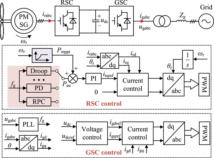
FIGURE 1. Grid connection control diagram of direct-drive PMSG wind power system.
For wind turbines within the same wind farm operating under the same wind speed conditions, their internal interactions can be ignored, and the wind farm can be approximated as an equivalent unit. During the inertia response phase of the power grid frequency, the influence of primary frequency control and secondary frequency control can be neglected. Therefore, the frequency response process of the grid-tied wind farm system can be described using the swing equation as
where f is the grid frequency, TJ is the inertia time constant, P is the power generated by the wind turbine system, and Pg is the power absorbed by the grid.
To retain FR capability, the power generated by the wind turbine P would include the MPPT power PMPPT and the auxiliary power Pau, i.e.,
In addition to the load power PL, the power absorbed Pg also includes inherent grid frequency response power, such as the power from the frequency response capability of asynchronous motor loads. Therefore, Pg can be expressed as
where Kg is the inherent grid frequency response coefficient, and fN is the rated frequency of the grid.
In the case of a disturbance ΔPL, both the grid and the wind turbine system need to respond to the disturbance power. Thus, combining (1), (2), and (3), the dynamic response model of the power system can be obtained as
Since the PMPPT is equal to the steady-state load power PL0, i.e., PMPPT = P0, (4) can be further simplified as
Without auxiliary FR power Pau, the power deviation on the right-hand side of (5) would be larger, resulting in greater frequency deviation and RoCoF, seriously affecting the system’s frequency stability. Therefore, it is very crucial for utilizing the grid-tied wind turbine system to provide necessary frequency support.
2.2 Pitch angle control
By adjusting the pitch angle of the wind turbine, the captured power can be altered, causing the operating point of the wind turbine to deviate from the maximum power point. It, in turn, provides the wind turbine with reserve capacity to participate in system FR. The specific operational principle of pitch angle control is analyzed as follows.
Wind energy is the kinetic energy generated by the flow of air and can be analyzed using aerodynamic theory. Specifically, the blades of a wind turbine can convert received wind energy into mechanical energy, and the captured mechanical power Pm can be represented as
where, ρ is the air density, R is the radius of the wind turbine blades, Cp is the wind energy capture coefficient, vm is the actual wind speed, β is the pitch angle of the blades, and λ is the tip-speed ratio of the wind turbine, which can be expressed as
where ωr is the rotational speed of the wind turbine rotor. It can be seen that for a certain type of wind turbine, the tip-speed ratio can be uniquely determined by the wind turbine speed ωr and wind speed vm.
It needs to be highlighted that apart from Cp and vm, the other parameters in (6) are mechanical structural parameters determined by the inherent structure of the wind turbine and cannot be altered after manufacturing, i.e., under certain wind speed conditions, the wind energy captured by the wind turbine is uniquely determined by the wind energy capture coefficient Cp. Therefore, a higher Cp captures more wind energy, while a lower Cp captures less. Additionally, the value of Cp is related to the tip-speed ratio λ and the pitch angle β, and their relationship can be described using a high-order nonlinear function as
The relationship between Cp, λ and β can be infered from (8), i.e., at a fixed wind speed, if the pitch angle remains constant, Cp is only affected by the wind turbine’s rotational speed ωr. At this point, the wind turbine has a specific speed that captures the maximum wind energy. If the wind turbine’s rotational speed remains constant, gradually decreasing the pitch angle results in an increased Cp, and thus more wind energy is captured. The additionally captured energy can then be utilized for FR, which is the fundamental principle of using pitch angle control for FR.
When employing pitch angle control, the auxiliary FR power of the wind turbine can be represented as:
where d is the derating rate used to characterize the wind turbine system’s reserve capacity, and Pmax is the maximum power.
As shown in Figure 2, the operational range of a direct-drive permanent magnet synchronous wind power generation system can generally be divided into four areas: grid-tied area, Cp constant area, rotor speed constant area, and power constant area. The grid-tied area represents the transition from the turbine being shut down to starting up, during which the turbine’s speed increases from 0 to ωr0. The second region is the Cp constant area (segments AB), where the turbine’s speed continuously increases to track the maximum power, while Cp remains at its maximum value. The third region is the rotor speed constant area (segment BC). As wind speed increases, the rotational speed of the wind turbine also increases until it reaches the maximum speed. However, the power output of the wind turbine has not yet reached its maximum value in this region, so the rotational speed remains constant. The fourth region is the power constant area (segment CD), and the control objective is to maintain the wind turbine’s output power near its rated value. Even as wind speed increases, the generator and inverter power remain at their maximum values. The pitch angle control proposed in this paper is performed within the power constant area.

FIGURE 2. Power tracking curve of permanent magnet direct-drive wind turbine.
Pitch angle control can be implemented through a simple PI control, Dai et al. (2022), which maintains a certain amount of reserve power in the power constant area to achieve dynamic frequency adjustment. The specific implementation is illustrated in Figure 3, where fg represents the grid frequency, fref is the reference frequency given, β0 is the rated pitch angle, and T is the time constant of the low-pass filter (LPF). To ensure the safe and stable operation of the wind turbine, the pitch angle should also operate within a certain safety range, and the rate of change of the pitch angle should be limited. βmin and βmax are the minimum and maximum values of the pitch angle, respectively, and the rate of change of the pitch angle is also restricted by a rate limiter module.
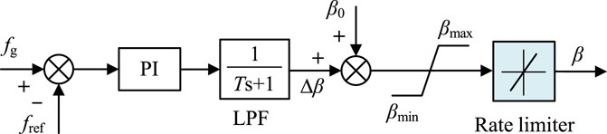
FIGURE 3. Principle diagram of pitch angle control.
Figure 4 displays the power output curves of the wind turbine under different control methods. The red curve PMPPT represents the output power curve under MPPT control, and the purple curve Pβ represents the output power curve under pitch angle control. It can be observed that pitch angle control leaves the wind turbine with reserve capacity. When a disturbance occurs, this reserve power can be released by adjusting the pitch angle, thus providing frequency support to the power system.
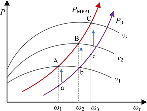
FIGURE 4. Comparison of wind turbine output power under different control methods.
2.3 Challenges of existing controls
Pitch angle control reserves spare capacity for wind turbine systems to participate in power system FR. Currently, the primary methods used to achieve system FR are droop control, inertia control, PD control and VSG control.
Droop control is the simplest frequency control scheme, introducing frequency deviations into the control loop to improve the FR of the wind turbine system. Since it acts as if it enhances the damping capacity of the grid, it is mainly used to suppress frequency deviations. As a result, the provided FR power of the droop control can be expressed as
where Kd is the droop coefficient and fN is rated frequency.
Inertia control introduces the RoCoF into the power control loop, effectively increasing the inertia level of the power system, and it can effectively reduce the RoCoF index of the power system. Thus, the provided FR power of inertia control is given by
where Ki is the inertia control parameter, and s is the differential operator.
PD control combines the advantages of both droop and inertia control, offering a better frequency response capability to the power system. The output FR power can be written as
where kp and kd are the proportional and derivative coefficients of PD control, respectively.
From the aforementioned analysis, it can be seen that both droop and inertia controls can be considered as special cases of PD control, Xiong et al. (2020); Dreidy et al. (2017). When Kd = 0, PD control becomes droop control, and when Kp = 0, PD control becomes inertia control. Therefore, PD control can be used to analyze the issues faced by these three control methods.
However, for PD control, it is a cumbersome issue for electing appropriate control parameters reasonably. As shown in Figure 5, if the control parameters are chosen inadequate, it is difficult to achieve the desired FR effect (e.g., curves Pi1 and Pd1), and the risk of frequency relay triggering still exists. On the other hand, larger control parameters might exceed the maximum power the wind turbine can provide (e.g., curves Pi2 and Pd2), still failing to achieving desired control results. While it is possible to find the optimal PD control parameters through rigorous mathematical analysis, these parameters heavily depend on power system parameters such as inertia and damping, which are difficult to obtain in practical power systems. Thus, finding the optimal PD parameters is challenging, and achieving the expected optimal PD control in practical engineering is almost impossible. Moreover, unreasonable PD parameters may even worsen the power system’s frequency indicators, negatively impacting its frequency stability. For instance, inappropriate inertia control parameters can lead to oscillation problems in the grid Zhang et al. (2024).
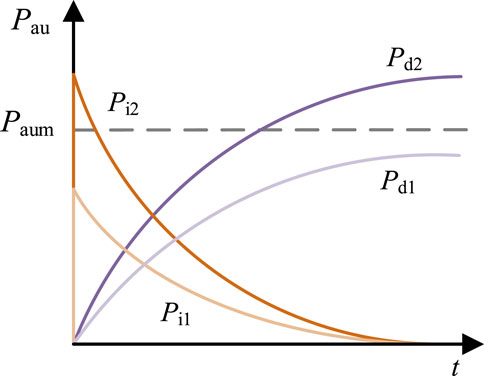
FIGURE 5. Frequency response characteristics under PD control.
VSG control may be a potential solution to the problems mentioned above. It simulates the rotor motion equation of a synchronous generator to provide inertia and damping capabilities to the power system. The pertinent mathematical model can be expressed as
where J is the inertia of the power system, D is the damping coefficient, and PG is the power output of the generators.
By designing J and D rigorously, the inertia and damping capabilities of the power system can be significantly enhanced, providing effective frequency support to the power system and reducing the risk of frequency relay action. However, as VSG control simulates the rotor motion equation of a synchronous generator, the inherent oscillation problem of synchronous generators still exists in wind power generation under VSG control, limiting the wide application of VSG control in wind power systems. Furthermore, due to the constraint of wind turbine pitch angle control’s spare capacity, designing the parameters J and D in VSG control poses difficulties. Inappropriate J and D parameters can still exceed the wind turbine’s spare capacity, deteriorating the power system’s frequency response characteristics.
3 RPC principle and implementation
3.1 Principle
As indicated from the analysis in the previous section, the main challenge in selecting PD control parameters arises from the limitation of wind turbine spare capacity and the difficulty in accurately obtaining inertia and damping parameters of the actual power system. Therefore, the core idea of the RPC principle is to utilize the entire available spare capacity of the wind turbine for FR during significant disturbances, abandoning linear control strategies. By doing so, the problem of difficult parameter tuning can be circumvented. Consider the derating rate of the wind power system as 0, i.e., d = 0. Combining (6) and (9), the wind turbine’s output power under this condition can be derived as
When applying the RPC principle for FR, the wind turbine’s maximum available auxiliary power Paum is used as the FR power provided by the wind turbine system, i.e.,
Substituting (15) into (5) yields the power system frequency response when the wind power system adopts the RPC control strategy, i.e.,
Solving the above differential equation provides the time-domain expression of power system frequency when the wind power system employs the RPC control strategy, namely,
From (17), the power system frequency deviation ΔfRPC under the RPC control strategy can be obtained as
Taking the derivative of (18) gives the RoCoF of the power system under the RPC control strategy as
When the wind power system adopts PD control, substituting (12) into (5) gives the power system frequency response model under the PD control strategy as
Solving (20) yields the time-domain expression of the power system frequency under the PD control strategy
Taking the derivative of (21) yields the rate of change of the power system frequency under the PD control strategy
Substituting (21) and (22) into (12), the additional FR power provided by the wind turbine under the PD control strategy can be obtained as
To avoid exceeding the wind turbine’s spare capacity limitation and achieve optimal PD control effects, the control parameters must satisfy:
Substituting (24) into (21) and (22), we have
Furthermore, by substituting (24) into (23), the following important conclusion can be drawn
By combining (25) and (26), it can be observed that under the constraint of the wind turbine’s maximum available spare capacity, the frequency response effect achieved through the RPC control strategy is equivalent to optimal PD control. This constitutes the specific principle of RPC control. Clearly, the adoption of RPC control can avoid the challenges of designing optimal PD parameters and reduces the complexity of controller design.
3.2 Implementation
Frequency deviation and RoCoF are two important indicators reflecting the grid’s frequency response characteristics. By comparing the operating ranges of these two indicators, the power system’s status can be assessed, indicating whether the system is in a power balance state and whether the generation system needs to increase or decrease power output. Specifically, when the frequency deviation is significantly larger than the deadband threshold and the RoCoF R is negative, it signifies an increase in load power of the power system. In this case, the wind turbine system should increase power generation to mitigate the impact of disturbance power on the power system frequency. Conversely, when the frequency deviation is significantly smaller than the deadband threshold and R is positive, it implies a decrease in load power in the power system. Here, the wind turbine system should decrease power generation. When both frequency deviation and RoCoF are negligible, it indicates that the power system has not been notably disturbed, and the wind turbine system does not need to provide extra FR power. Additionally, as the frequency deviation and RoCoF decrease gradually, in order to avoid consuming and occupying wind turbine FR resources with maximum spare capacity over prolonged periods, the system can smoothly exit the RPC FR mode using droop control.
Based on the above analysis, and according to different operational ranges of frequency indicators and considering the direction of disturbance power (increasing or decreasing load power), the RPC control strategy can be divided into the following four modes. The operational modes of each are explained as follows.
1. Steady State Mode: When the power system is not disturbed or only slightly disturbed, both the frequency deviation and RoCoF indicators are small, and the wind turbine system does not need to provide extra FR power.
2. Droop Control Mode: When the frequency deviation and RoCoF indicators of the power system reach certain values and exceed the FR deadband range, the wind power system needs to utilize droop control to provide a certain amount of FR power. Moreover, this mode can also be used to smoothly exit the state of using maximum available spare power.
3. Positive RPC Mode: When the power grid’s frequency deviation significantly increases or the RoCoF indicator drops significantly, exceeding the range tolerated by the droop mode, the wind turbine system needs to rapidly release power to effectively suppress further degradation of frequency indicators.
4. Negative RPC Mode: When the frequency deviation of the power system rapidly decreases or the RoCoF indicator rapidly increases, surpassing the operational range of both the steady state mode and droop control mode, it means that the power output of the system exceeds the absorbed load power. At this point, the wind turbine’s power output should be rapidly reduced.
The frequency indicators corresponding to different modes are shown in Table 1. Here, fdz and Rdz are the maximum allowable frequency deviation and RoCoF of the steady state mode. When the frequency indicators exceed these limits, the operational mode transitions from steady state mode to droop control mode. fd and Rd are the frequency deviation and RoCoF when transitioning from droop control mode to RPC control mode, respectively; they define the maximum operational threshold of the droop control mode. Frequency indicators exceeding these values will cause the system to transition from droop mode to RPC mode, where KD is the droop coefficient during this mode. The frequency thresholds corresponding to different FR modes can be determined according to various grid codes, Xiong et al. (2021). To ensure the safe operation of the power system, the following relationships must be satisfied by these mode thresholds.
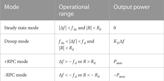
TABLE 1. Different operating modes and their operational ranges.
The transitions between different FR modes are illustrated in Figure 6. By evaluating the range of the power grid frequency indicators, the corresponding FR mode can be selected.
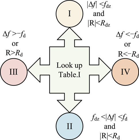
FIGURE 6. Transitions between different FR modes.
The RPC-based FR strategy proposed for direct-drive permanent magnet synchronous wind power generation system can be implemented according to the schematic in Figure 7. Firstly, using a Phase-Locked Loop (PLL) algorithm, the real-time frequency deviation and RoCoF indicators of the power system are measured online. Then, based on the measured frequency indicators’ operational range, the corresponding FR mode is selected according to Figure 6. Finally, the wind turbine power command in the control strategy shown in Figure 1 is adjusted to actively participate in the power grid FR process.
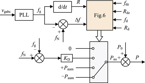
FIGURE 7. Implementation of the proposed RPC strategy.
4 Validation
To validate the effectiveness and advancement of the proposed wind power system FR strategy, this section conducts simulation analysis on the MATLAB/Simulink. The IEEE Four-Machine Two-Area (IEEE 4M2A) system serves as a testbed for studying power system dynamic stability, power flow, and damping oscillations. This system comprises 11 buses, four generators, and two areas connected through weak tie lines, Xiong et al. (2021). To test the FR performance of the wind power system, this study replaces Generator G3 in Area 2 of the IEEE 4M2A simulation system architecture with an equivalent 100 MW direct-drive permanent magnet synchronous wind power system, as shown in Figure 8. Table 2 provides the main parameters of the simulation model. Under pitch angle control, the wind turbine grid system can provide a spare capacity of 40 MW. When power disturbances occur, this section will extensively compare the time-domain waveforms of key physical quantities such as frequency, RoCoF, and output power of wind turbine system for the IEEE 4M2A simulation system under natural response, droop control, PD control, and the proposed RPC control.
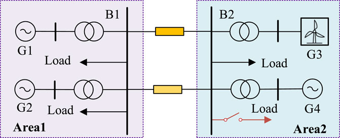
FIGURE 8. IEEE 4M2A system configuration.
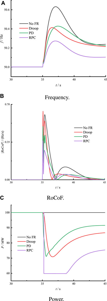
FIGURE 9. Frequency response of the system during single disturbance.
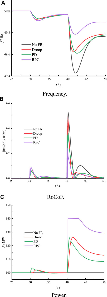
FIGURE 10. System frequency response during continuous disturbance scenario.
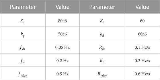
TABLE 2. Simulation parameters.
4.1 Single disturbance scenario
At 35 s, as shown in Figure 9, the load power suddenly drops by 70 MW, causing the frequency of the IEEE 4M2A system to gradually increase. Under natural response, the maximum frequency value reaches 50.62 Hz, and the maximum absolute value of RoCoF is 0.64 Hz/s. These values exceed the operating thresholds of frequency relays and RoCoF relays (0.5 Hz and 0.6 Hz/s, respectively), inevitably leading to a blackout. When droop control and PD control are respectively employed, the frequency peaks of the IEEE 4M2A system are 50.41 Hz and 50.42 Hz, and the maximum absolute values of RoCoF are 0.635 Hz/s and 0.5 Hz/s. Compared to the natural response, both indicators slightly decrease, improving the frequency response characteristics to some extent. Moreover, the simulation results also indicate that the frequency response results for the IEEE 4M2A system are similar when using these two control methods. However, PD control shows better suppression of RoCoF variation due to the smaller kp parameter, as it does not achieve a good frequency deviation suppression effect. This verifies the analysis results from Section 2, demonstrating that unreasonable PD parameters struggle to achieve a good frequency response. Regarding RPC control, since the wind power system autonomously switches to the -RPC mode during the significant disturbance, the wind turbine system’s output power decreases from 100 MW to 60 MW. As a result, the frequency peak of the IEEE 4M2A simulation system is only 50.27 Hz, and the maximum absolute value of RoCoF is 0.34 Hz/s. As the frequency gradually decreases, the wind power system’s FR strategy transitions back to the droop control mode. RPC control switches to droop control mode, and the wind turbine’s output power gradually increases according to droop control characteristics, avoiding the adverse effects of prolonged -RPC mode operation on the wind turbine system.
4.2 Continuous disturbance scenario
At 30 s, as shown in Figure 10, there is a sudden increase of 10 MW in the load, causing a slight reduction in the frequency of the IEEE 4M2A system and a slight fluctuation in RoCoF. Specifically, without any auxiliary frequency control service, the lowest point of the system frequency under natural response conditions is 49.91 Hz, with a maximum absolute RoCoF of 0.08 Hz/s. For droop control, the lowest frequency point of the IEEE 4M2A simulation system is 49.92 Hz, and the maximum absolute value of RoCoF is 0.078 Hz/s, suggesting a weak capability to suppress RoCoF. When using PD control, the lowest frequency point of the IEEE 4M2A system is approximately 49.93 Hz, with a maximum absolute RoCoF value of 0.06 Hz/s, due to the effect of the kd parameter in PD control inhibiting the increase of RoCoF. As for RPC control, at this point, both the frequency deviation and RoCoF of the IEEE 4M2A system are small, and the wind power grid system is in a steady-state operation mode. The changes in frequency and RoCoF indicators for the IEEE 4M2A system are the same as those under natural response conditions; since there is no need to provide additional frequency response power, wastage of FR power is avoided.
At 40 s, the load power of the IEEE 4M2A system suddenly increases by 60 MW, which is a large disturbance, causing a rapid decrease in the frequency and a significant increase in the RoCoF of the IEEE 4M2A system. Under the natural response condition, the system frequency rapidly drops to 49.42 Hz, and RoCoF reaches its peak value of 0.53 Hz/s. At this point, the frequency deviation is greater than the action threshold of the frequency relay (0.5 Hz), inevitably leading to a blackout. When using droop control and PD control, the lowest frequency points and RoCoF indicators of the IEEE 4M2A system are 49.63 Hz and 0.49 Hz/s, and 49.61 Hz and 0.39 Hz/s, respectively. The simulation results indicate that both droop control and PD control have some capacity to suppress frequency deviation and RoCoF indicators. However, when using RPC control, the lowest frequency point of the IEEE 4M2A system is 49.78 Hz, and RoCoF is 0.31 Hz/s. The lowest frequency point and RoCoF indicators are significantly lower than those of droop control and PD control, demonstrating optimal frequency response characteristics. The core reason is that when the frequency indicators of the IEEE 4M2A system exceed the threshold of the +RPC mode, the wind power system’s FR strategy switches to the +RPC mode. At this point, the wind turbine system’s output power reaches 140 MW, rapidly suppressing the frequency fluctuation phenomenon of the IEEE 4M2A system. When the frequency indicators return to the range of the droop control mode threshold, the wind turbine system’s output power gradually decreases according to the droop characteristics, achieving the expected goal of smoothly exiting the +RPC mode.
5 Conclusion
This paper proposes an FR strategy for a direct-drive permanent magnet synchronous wind power generation system based on the RPC principle, along with its implementation method. This strategy effectively reduces power system frequency deviation and RoCoF, while circumventing the challenge of optimal parameter tuning faced by traditional linear control methods. Through comprehensive theoretical analysis and comparative simulation verification, the following main conclusions are drawn.
1. Direct-drive permanent magnet synchronous wind power generation systems can reserve spare power through pitch angle control and actively participate in system FR when the grid experiences random disturbances.
2. Traditional control methods such as droop control, inertia control, and PD control are limited by spare capacity constraints and the difficulty of accurately determining grid inertia and damping parameters. Consequently, it is challenging to obtain control parameters that correspond to optimal FR performance, leading to suboptimal frequency response.
3. RPC control effectively utilizes the spare capacity of the wind turbine system. By continuously measuring grid frequency indicators and autonomously switching its FR control mode, it rapidly suppresses power system frequency fluctuations. The FR performance of RPC control is entirely equivalent to the frequency response of optimal PD control.
In future studies, the wind power system with grid forming converter will be analyzed for further modification of the RPC strategy proposed in this paper.
Data availability statement
The original contributions presented in the study are included in the article/Supplementary material, further inquiries can be directed to the corresponding author.
Author contributions
XZ: Conceptualization, Data curation, Formal Analysis, Software, Validation, Visualization, Writing–original draft, Writing–review and editing. DX: Conceptualization, Investigation, Project administration, Resources, Software, Validation, Visualization, Writing–original draft, Writing–review and editing. HZ: Validation, Writing–review and editing. JW: Investigation, Project administration, Supervision, Validation, Writing–original draft, Writing–review and editing.
Funding
The author(s) declare that no financial support was received for the research, authorship, and/or publication of this article.
Conflict of interest
Authors XZ and DX were employed by Electric Power Research Institute of State Grid Henan Electric Power Supply Co., Ltd.; Author JW was employed by State Grid Henan Electric Power Co., Ltd.
The remaining author declares that the research was conducted in the absence of any commercial or financial relationships that could be construed as a potential conflict of interest.
Publisher’s note
All claims expressed in this article are solely those of the authors and do not necessarily represent those of their affiliated organizations, or those of the publisher, the editors and the reviewers. Any product that may be evaluated in this article, or claim that may be made by its manufacturer, is not guaranteed or endorsed by the publisher.
References
Berrueta, A., Sacristan, J., Lopez, J., Rodríguez, J. L., Ursúa, A., and Sanchis, P. (2023). Inclusion of a supercapacitor energy storage system in dfig and full-converter pmsg wind turbines for inertia emulation. IEEE Trans. Industry Appl. 59, 3754–3763. doi:10.1109/tia.2023.3249145
Chauhan, P. J., Reddy, B. D., Bhandari, S., and Panda, S. K. (2019). Battery energy storage for seamless transitions of wind generator in standalone microgrid. IEEE Trans. Industry Appl. 55, 69–77. doi:10.1109/tia.2018.2863662
Dai, J., Ding, C., Zhou, X., and Tang, Y. (2022). Adaptive frequency control strategy for pmsg-based wind power plant considering releasable reserve power. Sustainability 14, 1247. doi:10.3390/su14031247
Dreidy, M., Mokhlis, H., and Mekhilef, S. (2017). Inertia response and frequency control techniques for renewable energy sources: a review. Renew. Sustain. Energy Rev. 69, 144–155. doi:10.1016/j.rser.2016.11.170
Guo, X., Zhu, D., Zou, X., Yang, Y., Kang, Y., Tang, W., et al. (2022). Analysis and enhancement of active power transfer capability for dfig-based wts in very weak grid. IEEE J. Emerg. Sel. Top. Power Electron. 10, 3895–3906. doi:10.1109/jestpe.2021.3089235
Li, Q., Ren, B., Li, Q., Wang, D., Tang, W., Meng, J., et al. (2022). Virtual inertial control strategy based on fuzzy logic algorithm for pmsg wind turbines to enhance frequency stability. Front. Energy Res. 10. doi:10.3389/fenrg.2022.907770
Liu, H., Li, M., Liu, L., and Shi, J. (2022a). Frequency trajectory planning-based transient frequency regulation strategy for wind turbine systems. IEEE J. Emerg. Sel. Top. Power Electron. 10, 3987–4000. doi:10.1109/jestpe.2021.3113822
Liu, H., Liu, X., Xiong, L., Li, M., and Zhu, Y. (2022b). Adaptive power compensation-based frequency regulation strategy of wind turbine system. IEEE J. Emerg. Sel. Top. Circuits Syst. 12, 260–267. doi:10.1109/jetcas.2022.3142452
Liu, W., Geng, G., Jiang, Q., Fan, H., and Yu, J. (2020). Model-free fast frequency control support with energy storage system. IEEE Trans. Power Syst. 35, 3078–3086. doi:10.1109/tpwrs.2019.2961955
Mousavi, Y., Bevan, G., Kucukdemiral, I. B., and Fekih, A. (2022). Sliding mode control of wind energy conversion systems: trends and applications. Renew. Sustain. Energy Rev. 167, 112734. doi:10.1016/j.rser.2022.112734
Musarrat, M. N., Islam, M. R., Muttaqi, K. M., and Sutanto, D. (2019). Enhanced frequency support from a pmsg-based wind energy conversion system integrated with a high temperature smes in standalone power supply systems. IEEE Trans. Appl. Supercond. 29, 1–6. doi:10.1109/tasc.2018.2882429
Ratnam, K. S., Palanisamy, K., and Yang, G. (2020). Future low-inertia power systems: requirements, issues, and solutions - a review. Renew. Sustain. Energy Rev. 124, 109773. doi:10.1016/j.rser.2020.109773
Saha, S., Saleem, M. I., and Roy, T. K. (2023). Impact of high penetration of renewable energy sources on grid frequency behaviour. Int. J. Electr. Power and Energy Syst. 145, 108701. doi:10.1016/j.ijepes.2022.108701
Sun, D., Liu, H., Gao, S., Wu, L., Song, P., and Wang, X. (2020). Comparison of different virtual inertia control methods for inverter-based generators. J. Mod. Power Syst. Clean Energy 8, 768–777. doi:10.35833/mpce.2019.000330
Sun, M., Min, Y., and Chen, L., (2021). Optimal auxiliary frequency control of wind turbine generators and coordination with synchronous generators. CSEE J. Power Energy Syst. 7, 78–85. doi:10.17775/CSEEJPES.2020.00860
Tu, G., Li, Y., and Xiang, J. (2022). Coordinated rotor speed and pitch angle control of wind turbines for accurate and efficient frequency response. IEEE Trans. Power Syst. 37, 3566–3576. doi:10.1109/tpwrs.2021.3136822
Van de Vyver, J., De Kooning, J. D. M., Meersman, B., Vandevelde, L., and Vandoorn, T. L. (2016). Droop control as an alternative inertial response strategy for the synthetic inertia on wind turbines. IEEE Trans. Power Syst. 31, 1129–1138. doi:10.1109/tpwrs.2015.2417758
Wang, H., Yang, J., Chen, Z., Ge, W., Ma, Y., Xing, Z., et al. (2018). Model predictive control of pmsg-based wind turbines for frequency regulation in an isolated grid. IEEE Trans. Industry Appl. 54, 3077–3089. doi:10.1109/tia.2018.2817619
Xiong, L., Liu, X., Liu, H., and Liu, Y. (2022). Performance comparison of typical frequency response strategies for power systems with high penetration of renewable energy sources. IEEE J. Emerg. Sel. Top. Circuits Syst. 12, 41–47. doi:10.1109/jetcas.2022.3141691
Xiong, L., Liu, X., Zhang, D., and Liu, Y. (2021). Rapid power compensation-based frequency response strategy for low-inertia power systems. IEEE J. Emerg. Sel. Top. Power Electron. 9, 4500–4513. doi:10.1109/jestpe.2020.3032063
Xiong, L., Liu, X., Zhang, D., and Zhuo, F. (2020). Modeling and stability issues of voltage-source converter dominated power systems: a review. CSEE J. Power Energy Syst. Early access 8 (6), 1530–1549. doi:10.17775/CSEEJPES.2020.03590
Yang, D., Wang, X., Yan, G.-G., Jin, E., Huang, J., Zheng, T., et al. (2023). Decoupling active power control scheme of doubly-fed induction generator for providing virtual inertial response. Int. J. Electr. Power and Energy Syst. 149, 109051. doi:10.1016/j.ijepes.2023.109051
Keywords: frequency regulation (FR), direct drive permanent magnet synchronous wind power generation system, rapid power compensation (RPC), pitch angle control, PD control
Citation: Zhang X, Xia D, Zhang H and Wang J (2023) Frequency regulation strategy of direct drive permanent magnet synchronous wind power generation system based on RPC principle. Front. Energy Res. 11:1309587. doi: 10.3389/fenrg.2023.1309587
Received: 08 October 2023; Accepted: 10 November 2023;
Published: 23 November 2023.
Edited by:
Yonghui Liu, Hong Kong Polytechnic University, Hong Kong SAR, ChinaReviewed by:
Dejian Yang, Northeast Electric Power University, ChinaHuimin Wang, Zhejiang Sci-Tech University, China
Jianquan Shi, Nanjing Institute of Technology (NJIT), China
Copyright © 2023 Zhang, Xia, Zhang and Wang. This is an open-access article distributed under the terms of the Creative Commons Attribution License (CC BY). The use, distribution or reproduction in other forums is permitted, provided the original author(s) and the copyright owner(s) are credited and that the original publication in this journal is cited, in accordance with accepted academic practice. No use, distribution or reproduction is permitted which does not comply with these terms.
*Correspondence: Hengyou Zhang, emhhbmdoeTIxQG1haWxzLmpsdS5lZHUuY24=