 Jinliang Xie
 Zongjie Mu1*
- 1The Karamay Branch of State Key Laboratory of Petroleum Resources and Engineering, China Petroleum University-Beijing at Karamay, Beijing, China
- 2Downhole Service Company of Xibu Drilling Engineering Company, Beijing, China
Horizontal well technology is a promising method for oil and gas development. During cementing operations in horizontal wells, it was found that conventional casing centralizers could not meet the requirements for casing cementing in expanded wellbores. Therefore, a new type of casing centralizer needs to be designed for horizontal well sections that have undergone enlargement. By analyzing the most common materials currently used, 45 steel was selected for the spring leaf of the novel casing centralizer. To evaluate the centralization effect of the horizontal well casing centralizer, a casing centralization degree evaluation function was established, and a wellbore-centralizer mechanical model was proposed using the finite element method to simulate the working conditions of the centralizer spring leaf in ϕ215.9 and ϕ311.2 mm well sections. On this basis, a wellbore-centralizer-casing coupling model that does not consider the effect of wellbore fluid on the casing was established to simulate the centralization characteristics of the new casing centralizer and traditional centralizer under different wellbore sizes. Simulation results show that the average casing centralization degree of the new centralizer is 85.53%, while that of the traditional centralizer is 55.58%. That is, the horizontal well casing centralizer can maintain a good centralization effect on the casing string.
1 Introduction
During the conventional oil and gas development processes, the quality of cementing plays a vital role. Insufficient cementing quality can prevent the achievement of expected production outcomes and may even lead to severe operational accidents (De Andrade and Sangesland, 2016; Zhang and Wang, 2017; Ma et al., 2022). With the advancement of exploration techniques in the petroleum industry in China, the development methods have become increasingly diverse (Dao et al., 2023). Among these methods, the utilization of horizontal wells and large-scale hydraulic fracturing has emerged as a significant solution for petroleum resource development (Lei et al., 2022; 2021). Additionally, as conventional oil and gas reservoirs deplete, there is growing attention towards the development of unconventional oil and gas reservoirs (Jiao, 2019; Al-Shami et al., 2021). In the ongoing exploration of unconventional reservoirs, the implementation of large-scale multistage hydraulic fracturing has become a crucial approach for exploiting these resources (Jia et al., 2012; Jia and Tian, 2012; Li et al., 2020).
Casing centralization refers to the degree of alignment between the casing axis and the wellbore axis. The proper centration of casing is crucial for the quality of subsequent cementing operations. The use of casing centralizers is the only tool for maintaining casing centralization and safeguarding cementing quality (Sabins, 1990; Liu and Weber, 2012; Sanchez et al., 2012). However, conventional centralizers face technical limitations when employed in wellbore sections with expanded diameters, leading to inadequate centralizing forces exerted on the casing (Xianglin et al., 2010). As a consequence, gravity influences the casing during cementing, causing downward displacement towards the wellbore and resulting in the formation of an uneven annular gap around the casing, as shown in Figure 1. Within the cementing operation, the presence of an eccentric annular gap hinders the effective displacement of drilling fluids during the cement slurry displacement process (McLean et al., 1967). This leads to uneven cement thickness and incomplete cementing around the wellbore after cementing (Salehi and Paiaman, 2009; Zhao et al., 2016), preventing the cementing quality in horizontal wells from meeting subsequent construction requirements (Jung and Frigaard, 2022). In the hydraulic fracturing development process, poor cementing effects in certain wellbore sections can lead to issues such as inter-well interference (Zhao et al., 2016; Liu et al., 2023), cement sheath failure (Zhao et al., 2019; Kuanhai et al., 2020), and casing deformation (Al Farsi, 2014; Han et al., 2022; Shangyu et al., 2023).
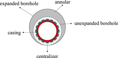
FIGURE 1. Illustration of the cementing effect of conventional well supporters in conventional and borehole expansion wells.
In current research on casing centralizers, the focus has primarily been on reducing the surface friction (Dall’Acqua et al., 2022; Kinzel and Calderoni, 1995) and enhancing the design strength of traditional centralizers to address the issue of high down-entry friction (Javier et al., 2015; Rodrigue et al., 2019). Efforts have been made to improve cementing by utilizing modified bow-spring centralizers (Peckins et al., 2001). However, there is limited research on the ineffective centralization performance of conventional centralizers in expanded wellbores.
Mu et al. (Mu et al., 2020) addressed the demand for casing centration in construction activities within expanded wellbore sections by designing a novel centralizer. This tool employs an underground hydraulic activation mechanism, which avoids issues such as high down-entry friction during the centralizer’s deployment, while also mitigating the potential damage to the wellbore wall that can occur with traditional bow-spring centralizers (Urdaneta Nava and Farley, 2020). It possesses the advantages of providing strong downhole casing support and meeting the requirements for centration during construction in expanded wellbore sections of horizontal wells. Despite the results, the current research lacks investigations on material selection for the new centralizer, analysis of downhole conditions, and evaluations of the centralization effects at the wellbore bottom.
In this study, a finite element analysis method was employed to establish models for the wellbore-centralizer system and the wellbore-centralizer-casing system, enabling mechanical analyses. The investigation aimed to elucidate the influence patterns of hydraulic conditions, materials, and operating conditions on the centralization effectiveness of the hydraulic centralizer. Our works in present paper are expected to offer valuable insights for enhancing the casing centralization performance of hydraulic centralizers.
2 Structure and working mechanisms of new centralizer
2.1 Structure of new centralizer
The casing centralizer primarily consists of the following components, as illustrated in Figure 2. The coupling serves as the connection point for the centralizer, ensuring the flow of fluids within the tool towards the casing centralizer. The body is externally designed with a thrust sleeve, thrust ring, hydraulic cylinder, spring plates, connecting sleeve, and lower cone sleeve.
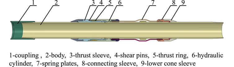
FIGURE 2. Brief diagram of the new casing centralizer.
The thrust ring is positioned between the thrust sleeve and the outer sleeve, employing an inverse tooth structure to prevent any backward movement of the mechanism after forward motion. Sealing rings are utilized to establish a seal between the thrust sleeve, thrust ring, hydraulic cylinder, and the body, while threaded sealing is employed between the remaining components and the body. The arrangement and functionality of these components contribute to the overall performance and effectiveness of the casing centralizer.
2.2 Working principle
The casing centralizer is lowered into the well along with the casing and positioned at the designated location, as shown in Figure 3A. Once in place, the ball is sent into the well. The fluid present within the well aids in the movement of the ball towards the seat. Owing to the fact that the diameter of the seat is smaller than that of the ball, the ball ceases movement upon reaching the seat. As the pump pressure escalates, there is a corresponding increase in the local pressure of the cylinder. This results in the ball becoming hydraulically lodged onto the ball seat, thereby creating a sealed environment. As the pressure builds up within the centralizer’s hydraulic cylinder, and fluid enters the hydraulic cylinder through the designated fluid inlet in the tool. The high-pressure fluid propels the hydraulic cylinder forward, causing intermittent shear pin failure and initiating stress concentration in the pre-determined arched positions of the spring plates. This leads to the opening of the spring plates at the arched positions, and the bottom spring plates push the casing upward until the upper spring plates come into contact with the wellbore wall.

FIGURE 3. Demonstration of the centralizer workflow.
A groove-shaped thrust sleeve is incorporated between the hydraulic cylinder and the thrust sleeve to ensure that the spring plates remain open even after pressure is released, thus ensuring the centralization effectiveness of the entire tool, as depicted in Figure 3B. The evenly distributed spring plates, activated by hydraulic pressure from the hydraulic cylinder, ensure a uniform opening, thereby guaranteeing the casing’s centration within the wellbore space. After that, when the cement slurry returns to the wellhead, the injection is stopped and the cement cement operation is completed, as shown in Figure 3C.
3 Model description and numerical simulation details
3.1 Simulation model
Spring plates are hydraulically actuated by the cylinder to achieve the required deformation for casing centration. The hydraulic cylinder of the tool incorporates a thrust shaft component to enforce the centralizing force on the tubular column through the spring plates. During the hydraulic transmission process, the cylinder is propelled by hydraulic pressure, which, in turn, drives the spring plates. The spring plates are fixed to the lower fixed sleeve, and a simplified analysis of the hydraulic casing centralizer model is conducted by establishing the constraints between the cylinder, spring plates, and fixed sleeve. The three-dimensional model is established, as depicted in Figure 4.
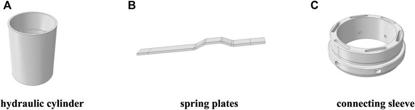
FIGURE 4. Structures of hydraulic cylinder, spring plates and connecting sleeve.
A hydraulic load P is applied at the upper end of each individual spring plate, which is pre-set with a certain inclination angle. This configuration induces significant elastic-plastic deformation at point M, exerting a thrust force FN on the wellbore wall, as illustrated in Figure 5. The maximum Mises stress of the spring plates is selected as the evaluation criterion to analyze the influence of the mesh density on the accuracy of the simulation results.
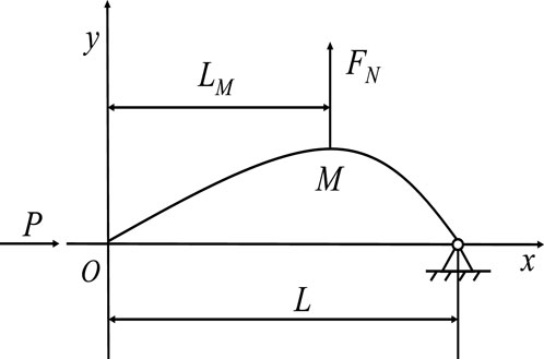
FIGURE 5. sketch of Spring plate structure.
During the function fitting process, it was found that the results using Boltzmann function regression exhibits strong correlation and minimal residuals, effectively describing the relationships between pressure load and the displacement of the spring plate. This indicates a clear physical interpretation. The Boltzmann function form for characterizing the deformation of the spring plates is established as follows:
where, y represents the maximum deformation of the casing centralizer, in millimeters; x denotes the applied load in MPa; A1, A2, dx, and x0 are coefficients.
The actual performance of casing centralizers in downhole operations is a crucial criterion for evaluating their design effectiveness. Simulating real operating conditions allows for the visual observation of the impact of casing centralizers on cementing outcomes. In this study, models were developed to analyze the construction sections, including a model with a conventional wellbore diameter (ϕ215.9 mm) and a model with an expanded wellbore diameter (ϕ311.2 mm), as shown in Figure 6.
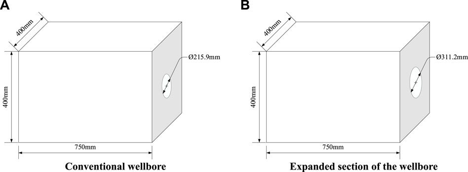
FIGURE 6. Conventional wellbore and expanded wellbore models.
Due to practical constraints, finite element modeling was employed to establish a three-dimensional model of the casing centralizer and the wellbore (Figure 7), enabling the simulation of casing centralizer performance in both conventional and expanded wellbore sections.
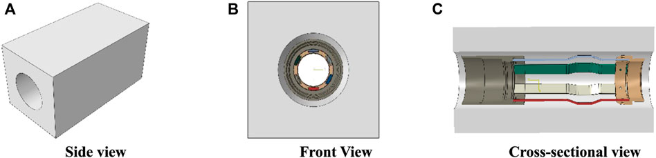
FIGURE 7. Demonstration of wellbore-casing centralizer model.
After setting the boundary conditions and meshing, a hydraulic load was applied to the casing centralizer at the hydraulic cylinder. Upon applying the load, the spring plates underwent deformation.
The centralization of the casing can be quantified using the casing eccentricity, which is calculated as follows:
In the equation, Ah represents the wellbore axis in mm; Ac represents the casing axis in mm; e represents the casing eccentricity in mm; ε represents the casing centralization in %; Dh represents the wellbore diameter in mm; and Dc represents the outer diameter of the casing in mm.
Assuming that the downhole tubulars are not influenced by the downhole fluids, we establish a wellbore-casing centralizer-casing model to evaluate the centralization performance of the tool, as shown in Figure 8. The spacing between the casing centralizers in the horizontal section of the well is set at 12.0 m (Lee et al., 1986). In the model, a 15 m long horizontal section is designed, and a centralizer is installed at the end of the casing to analyze the casing centralization. Currently, most centralizers used in horizontal wells are rigid centralizers. We establish a model for a conventional rigid centralizer with the following parameters: outer diameter of 172 mm, inner diameter of 60 mm, and tool length of 500 mm. The horizontal well casing adopts an outer diameter of 139.7 mm and an inner diameter of 121.4 mm.
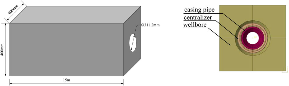
FIGURE 8. Wellbore-casing centralizer -casing model.
3.2 Parameter description
The hydraulic cylinder and fixed sleeve are made of 35CrMo material, while the material for the spring leaf is selected from 45 steel, 35CrMo, and 60Si2Mn. Parameters of the three materials are listed in Table 1.
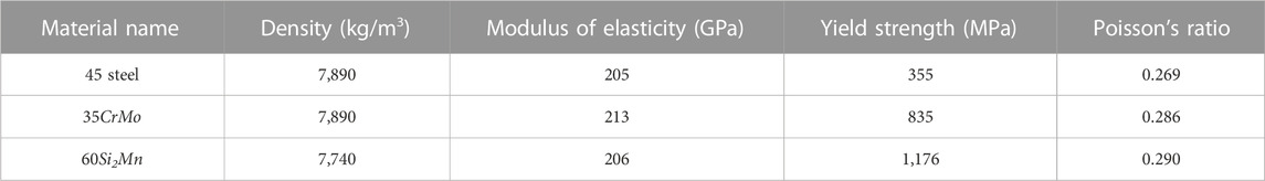
TABLE 1. Parameters for 45 steel, 35CrMo, and 60Si2Mn.
The downhole condition simulation involves simulating the opening of the casing centralizer in the wellbore and applying fixed constraints around the wellbore, as shown in Figure 9. When the spring plates are opened and supported against the wellbore wall, it is assumed that there is no sliding between the spring plates and the wellbore wall, and sliding friction contact is neglected. The outer surface of the spring plates is assumed to have full-face contact with the inner wall of the wellbore. The remaining components of the tool are designed with general contact.
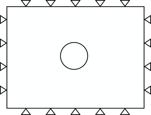
FIGURE 9. Boundary condition setting.
3.3 Grid independence verification
To ensure the reliability of the grid partitioning in the numerical model, grid independence verification was performed. The hydraulic casing centralizer is primarily responsible for providing centering and aligning effects for the casing, thus the focus of the grid independence study is on the spring plate.
The numerical simulation experiment with grid independence analysis was conducted under the boundary condition of hydraulic pressure of 70 MPa. The results, as shown in the Figure 10, indicate that when the number of grids exceeds 100,000, the relative error of the maximum equivalent displacement remains within 5%. Considering the impact on computational resources, a global seed size of 1 was selected, resulting in a total of 105,780 grids.
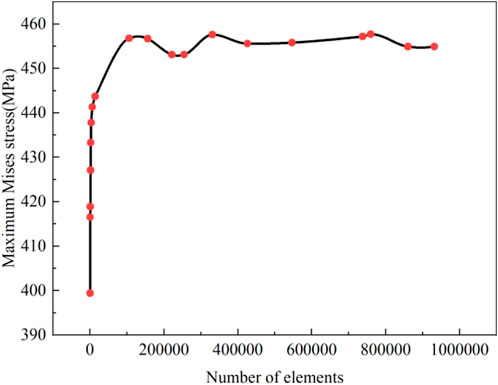
FIGURE 10. The relationship between the number of grid cells and the maximum equivalent force.
The spring plate, outer sleeve, and wellbore components were discretized using 8-node linear reduced integration hexahedral elements (C3D8R) for grid partitioning, while the lower and upper connecting sleeves were discretized using conventional 10-node tetrahedral elements (C3D10). The grid partitioning results are shown in Figure 11.
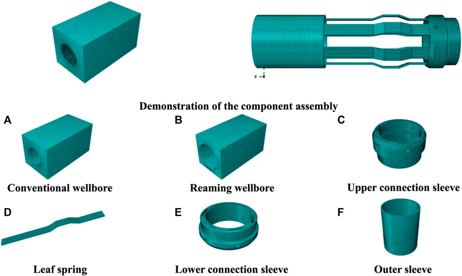
FIGURE 11. Component assembly and meshing.
4 Result and analysis
4.1 Material preference
To investigate the impact of hydraulic load on the spring plate, finite element analysis was conducted on an individual spring plate made of 45 steel material. The analysis yielded the relationship between the load and the deformation of the spring plate, as illustrated in Figure 12.
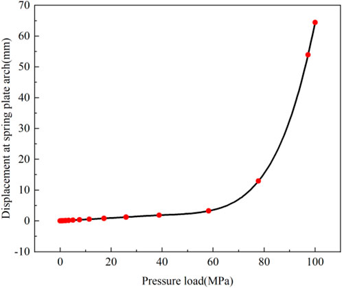
FIGURE 12. Relationship between hydraulic load and maximum deformation of spring plate.
The data shown in Figure 12 were fitted, resulting in the relationship between the hydraulic load and the maximum deformation of the spring plate. The fitted equation is as follows:
The fitted curve, with a correlation coefficient of R2 = 0.99961 (>0.99), indicates a good fit. According to Eq. 3, when a load of 93.64 MPa is applied at the end of a single spring plate, the maximum deformation at the top of the spring plate reaches 41.001 mm. This meets the construction requirements for the majority of expanded diameter well sections.
Finite element analysis was conducted on the aforementioned spring plates made of the three different materials to obtain the relationship between the maximum Mises stress, as well as the displacement at the top of the spring plates (Figure 13).
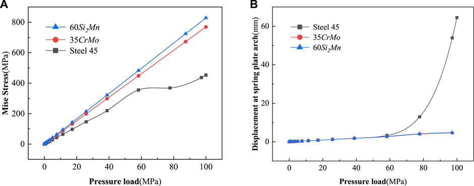
FIGURE 13. Relationship between pressure load and (A) maximum Mises stress and (B) tip displacement of different materials.
As shown in Figure 13A, with increasing pressure load, the maximum Mises stress of the spring plates made of the three materials rapidly increases. The rate of increase is higher for the structures made of 60Si2Mn and 35CrMo materials compared to that made of 45 steel. After the pressure load exceeds 60 MPa, the maximum Mises stress of the structures made of 60Si2Mn and 35CrMo materials remains below their yield strengths, while the structure made of 45 steel exceeds 355 MPa and undergoes yielding. During the pressure load stage between 60 MPa and 100 MPa, the maximum Mises stress of the structures made of 60Si2Mn and 35CrMo materials still remains below their yield strengths, indicating elastic behavior throughout the loading phase. However, the structure made of 45 steel experiences plastic deformation in elements after the pressure load exceeds 60 MPa.
Figure 13B illustrates that the displacement at the top of the spring plates made of the three materials increases with the increasing pressure load. However, the structure made of 45 steel exhibits the most significant increase. Specifically, above 60 MPa, the rate of displacement increased exponentially for the structure made of 45 steel, compared to just linear increases for the other two materials. In the case of the expanded section of the wellbore, where the outer diameter of the wellbore reaches 311.2 mm, the structure made of 45 steel satisfies the construction requirements. However, the other two materials are not capable of meeting the on-site demands effectively, as shown in Table 2.
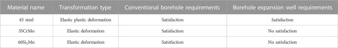
TABLE 2. Comparison between different materials.
In summary, the structure made of 45 steel exhibits plastic deformation when the load exceeds 60 MPa. The rate of increase in displacement at the top of the structure also becomes more significant. Due to the occurrence of plastic deformation, the deformed structure does not exhibit elastic recoil. On the other hand, the structures made of the other two materials remain in the elastic phase throughout the entire load application, and their top displacement fails to meet the on-site conditions. Therefore, 45 steel is selected as the material for the spring plates.
4.2 Evolution of stress-strain process
Numerical simulation was conducted to analyze the spring plates in models with different wellbore diameters. The simulation results reveal that in the wellbore sample with a diameter of 215.9 mm, the casing centralizer is positioned at the center of the wellbore, with the spring plates protruding by a distance of 14.10 mm and closely adhering to the wellbore wall, indicating good centralization performance. The simulation further indicates that after contacting the wellbore wall, the spring plates in the ϕ215.9 mm wellbore continue to move forward, providing additional internal compression force. This increases the contact area between the spring plates and the wellbore wall, enhances the internal squeezing force, and improves the centralization performance of the tool. In the wellbore sample with a diameter of 311.2 mm, the casing centralizer is also positioned at the center of the wellbore, with the spring plates protruding by a distance of 61.45 mm and closely adhering to the wellbore wall. After the spring plates are in contact with the wellbore wall, the provided stop-retreat axle locks the hydraulic cylinder and provides a reactive force to the spring plates for centralization, ensuring the working performance of the casing centralizer. Figure 14 illustrates the 10-s deformation process of the spring plates in the wellbore.
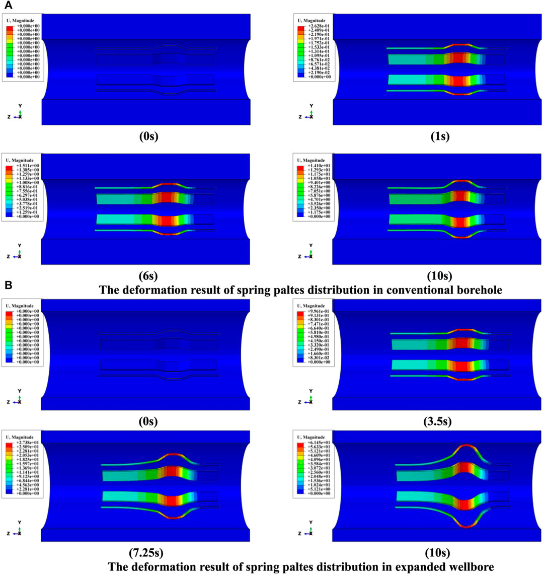
FIGURE 14. Deformation profile of the casing retainer in the wellbore model.
The spring plate is a crucial component of the casing centralizer that provides the centralization effect. To analyze the centralization performance of the casing centralizer more effectively, the finite element calculation results of the spring plate were extracted and analyzed separately, as shown in Figure 15.
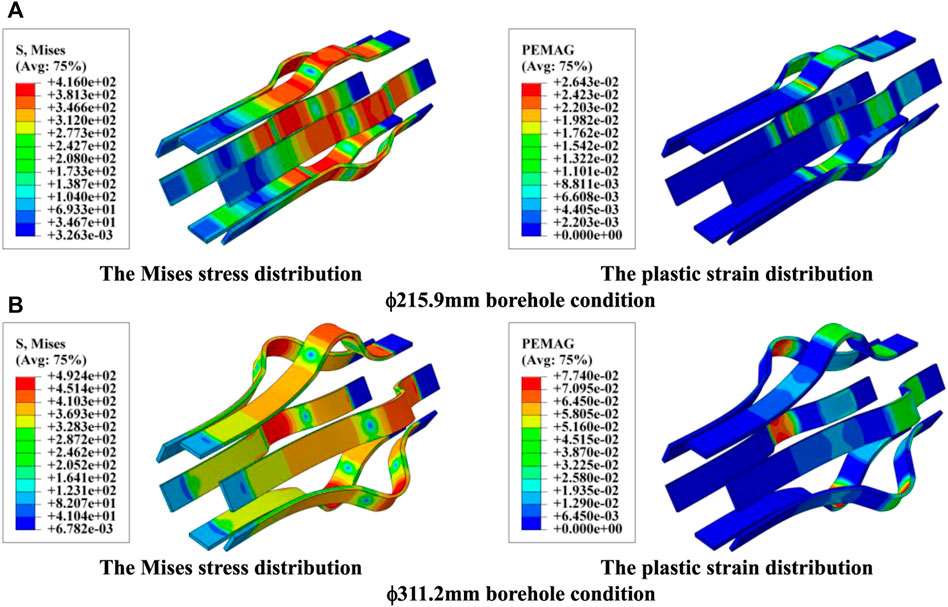
FIGURE 15. Deformation results of spring plate in horizontal wells.
The resulting contour plots illustrate the Mises stress distribution and plastic strain distribution of the spring plate after deformation in both the non-expanded and expanded wellbores, as shown in Figure 15. In the non-expanded wellbore, the hydraulic pressure continues to push the hydraulic cylinder forward, exerting pressure on the rear of the casing centralizer, leading to stress concentration in the arch region. In the contour plot of the non-expanded wellbore, the maximum Mises stress is 383.4 MPa, and the maximum plastic strain is 0.001386. In the contour plot of the expanded wellbore, the maximum Mises stress is 492.4 MPa, and the maximum plastic strain is 0.07740.
From the contour plots, it can be observed that stress concentration occurs in the arch region of the spring plate, accompanied by plastic deformation in that area, as shown in Figure 15. In the expand wellbore section, each spring plate exhibits a top displacement of approximately 61.45 mm, as shown in Figure 14B. At this point, the hydraulic cylinder advances by 18.27 mm, while the design of the casing centralizer allows for a maximum cylinder displacement of 28 mm. The simulation results demonstrate that the casing centralizer is capable of meeting the requirement of centralizing the casing in the horizontal expanded wellbore section.
4.3 Application effectiveness forecast
Two types of casing centralizers, namely, the new centralizer and the conventional rigid centralizer, were installed at the ends of the casing string. Finite element analysis was conducted to determine the vertical displacement of the casing using these two centralizers, and the results are presented in Figure 16.
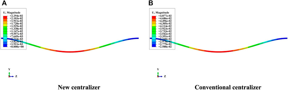
FIGURE 16. Comparison of deformation contours of (A) new casing centralizer and (B) conventional casing centralizer.
The data extracted from the numerical simulation results were used to calculate the eccentricity of the casing. The results are presented in Figure 17.
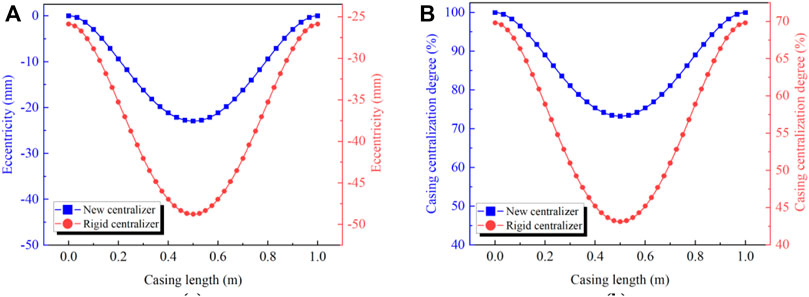
FIGURE 17. Comparison between (A) the conventional rigid centralizer and (B) the new centralizer in terms of eccentricity and casing centralization degree.
Figure 17A shows that the eccentricity at the location of the casing centralizer in the expanded section of the wellbore is zero. Due to gravity, the axis of the casing deviates from the wellbore axis in the middle section of the casing. By contrast, when using conventional rigid centralizers, their limited correcting effect in the expanded section prevents the casing from being centered, resulting in suboptimal centralization of the entire casing. To better present the evaluation criteria, Figure 17A is replotted in terms of the centralization degree in Figure 17B. It is clear that the centralization degree of the casing with conventional centralizers is significantly lower than that with new casing centralizers. The optimal centralization occurs at the position of the rigid centralizer installation, with a centralization degree of approximately 69.82%, while the worst centralization occurs at the midpoint between the two centralizer installation positions, with a centralization degree of approximately 43.14%. The average centralization degree of the casing with rigid centralizers is 55.58%. On the other hand, the casing equipped with hydraulic casing centralizers exhibits optimal centralization at the centralizer placement position, with a centralization degree of 100%. The worst centralization occurs at the midpoint between the two centralizer installation positions, with a centralization degree of approximately 73.25%. The average centralization degree of the casing with casing centralizers is 85.74%.
Based on the results of numerical simulations, comparisons of casing eccentricity and centralization, it was observed that the degree of centralization for casing strings equipped with conventional rigid centralizers was suboptimal, with deviations occurring at the centralizer installation. However, the implementation of a new centralizer design has addressed this issue, resulting in an increase in the average degree of casing centralization by 30.16%.
4.4 Indoor experimental verification
An indoor experiment was conducted to test the effectiveness of the new casing centralizer. In this experiment, we used clear water to replace the cement slurry circulating in the casing and conducted the experiment at room temperature. We used hydraulic testing to evaluate the performance of the new casing centralizer (Figure 18).
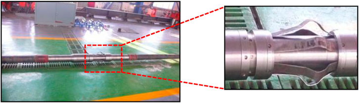
FIGURE 18. Activated centralizer with the spring plate open.
Based on the experimental conditions described above, the following results were obtained.
1. The spring leaf opened smoothly. When the pump pressure rose to 12 MPa, the shear pin was cut off, and the spring leaf quickly expanded.
2. After maintaining a pressure of 30 MPa for 20 min, the test pump showed no pressure drop, and the spring plates did not retract upon pressure release. This indicates that the hydraulic cylinder exhibited good sealing performance.
3. After 24 h, measurements were taken of the spring plates, which remained in an open state without any rebound. The deformation observed in the arched position of the spring plates aligned with both numerical and experimental results, providing evidence that the casing centralizer can effectively maintain the centralization of the casing string.
These results demonstrate that the casing centralizer effectively ensures the expansion and sealing of the spring plates, verifies the sealing performance of the hydraulic cylinder, and confirms the ability of the new centralizer to maintain proper centralization of the casing string.
5 Conclusion
To investigate the material selection for the new centralizer and evaluate its centralization effects under actual operating conditions, in this work, a spring plate model was established, models of a conventional wellbore-casing centralizer system and an expanded wellbore-casing centralizer system were established to determine the effect of the casing centralizer in the horizontal section, and a wellbore-casing centralizer-casing model was established. A comparative analysis was conducted between a conventional rigid centralizer and the casing centralizer. The findings lead to the following conclusions.
1. Based on the displacement of the spring plate’s top end, the material for the casing centralizer was optimized, and it was determined that the spring plate performed optimally when made of 45 steel.
2. Modeling results show that the spring plates of the casing centralizer experienced stress concentration and plastic deformation in the arched region, preventing the spring plates from rebounding while increasing the displacement at the top end, thereby enhancing their effectiveness.
3. The average casing centralization when using the conventional rigid centralizer was 55.58%, while the new casing centralizer achieved 85.74% centralization. This resolves the issues of high friction during the installation of conventional rigid centralizers and poor casing centralization. In laboratory tests using water as the medium, the spring plates rapidly expanded when the pump pressure reached 12 MPa. The spring plates remained in their expanded state without any rebound after 24 h.
Data availability statement
The original contributions presented in the study are included in the article/Supplementary material, further inquiries can be directed to the corresponding author.
Author contributions
JX: Writing–original draft, Writing–review and editing. ZM: Writing–review and editing. BL: Software, Writing–review and editing. CZ: Writing–review and editing. YG: Writing–review and editing.
Funding
The author(s) declare that financial support was received for the research, authorship, and/or publication of this article. The National Natural Science Foundation of China (Grant No. 52274017), Natural Science Foundation of Xinjiang Uygur Autonomous Region (Grant No. 2021D01E23) and Youth Science and Technology Top Talent Project of Tianshan Elite (2022TSYCCX0052).
Acknowledgments
The authors give their thanks to the financial support of The National Natural Science Foundation of China (Grant No. 52274017), Natural Science Foundation of Xinjiang Uygur Autonomous Region (Grant No. 2021D01E23) and Youth Science and Technology Top Talent Project of Tianshan Elite (2022TSYCCX0052).
Conflict of interest
Author BL was employed by Downhole Service Company of Xibu Drilling Engineering Company.
The remaining authors declare that the research was conducted in the absence of any commercial or financial relationships that could be construed as a potential conflict of interest.
Publisher’s note
All claims expressed in this article are solely those of the authors and do not necessarily represent those of their affiliated organizations, or those of the publisher, the editors and the reviewers. Any product that may be evaluated in this article, or claim that may be made by its manufacturer, is not guaranteed or endorsed by the publisher.
References
Al Farsi, G. (2014). “Casing failures correlated with cementing quality in steam injection wells,” in Presented at the SPE Annual Technical Conference and Exhibition, Amsterdam, Netherlands, October, 2014. doi:10.2118/173483-STU
Al-Shami, T. M., Jufar, S. R., Negash, B. M., and Abdullahi, M. B. (2021). Impact of external excitation on flow behavior of trapped oil blob. J. Petroleum Sci. Eng. 196, 108002. doi:10.1016/j.petrol.2020.108002
Dall’Acqua, D., Taubner, S., Miller, S. M., Clark, J., and Gladney, M. (2022). “Improved out-of-slip casing running efficiency in A shale ERD application combining fixed casing centralization and rotation to reduce openhole running friction,” in Presented at the SPE Annual Technical Conference and Exhibition, Houston, Texas, USA, October, 2022, D031S055R006. doi:10.2118/210279-MS
Dao, N. H., Mahjoub, M., Menand, S., and Nguyen, K. L. (2023). Modeling of a detailed bow spring centralizer description in stiff-string torque and drag calculation. Geoenergy Sci. Eng. 222, 211457. doi:10.1016/j.geoen.2023.211457
De Andrade, J., and Sangesland, S. (2016). Cement sheath failure mechanisms: numerical estimates to design for long-term well integrity. J. Petroleum Sci. Eng. 147, 682–698. doi:10.1016/j.petrol.2016.08.032
Han, M. T., Pu, B. Y., Cheng, Z. H., Fu, J. H., Zhang, J., and Ma, T. S. (2022). Numerical simulation of casing strength in salt-gypsum stratum deep well. Strength Mater 54, 134–143. doi:10.1007/s11223-022-00387-2
Javier, U., Mauricio, T., Carlos, G., Luis, Q., Ramirez, Z., Silva, P., et al. (2015). “Application of friction reducing rigid-resin centralizers based on silicon carbide,” in Presented at the SPE Middle East Oil and Gas Show and Conference, Manama, Bahrain, March, 2015. doi:10.2118/172559-MS
Jia, C., Zheng, M., and Zhang, Y. (2012). Unconventional hydrocarbon resources in China and the prospect of exploration and development. Petroleum Explor. Dev. 39, 139–146. doi:10.1016/S1876-3804(12)60026-3
Jia, S. G., and Tian, Y. (2012). Development of hydraulic fracturing new technique. Adv. Mater. Res. 524–527, 1378–1381. doi:10.4028/www.scientific.net/AMR.524-527.1378
Jiao, F. (2019). Re-recognition of “unconventional” in unconventional oil and gas. Petroleum Explor. Dev. 46, 847–855. doi:10.1016/S1876-3804(19)60244-2
Jung, H., and Frigaard, I. A. (2022). Evaluation of common cementing practices affecting primary cementing quality. J. Petroleum Sci. Eng. 208, 109622. doi:10.1016/j.petrol.2021.109622
Kinzel, H., and Calderoni, A. (1995). Field test of a downhole-activated centralizer to reduce casing drag. SPE Drill. Complet. 10, 112–114. doi:10.2118/26752-PA
Kuanhai, D., Yue, Y., Yi, H., Zhonghui, L., and Yuanhua, L. (2020). Experimental study on the integrity of casing-cement sheath in shale gas wells under pressure and temperature cycle loading. J. Petroleum Sci. Eng. 195, 107548. doi:10.1016/j.petrol.2020.107548
Lee, H. K., Smith, U. C., and Tighe, R. E. (1986). Optimal spacing for casing centralizers. SPE Drill. Eng. 1, 122–130. doi:10.2118/13043-PA
Lei, Q., Weng, D., Xiong, S., Liu, H., Guan, B., Deng, Q., et al. (2021). Progress and development directions of shale oil reservoir stimulation technology of China National Petroleum Corporation. Petroleum Explor. Dev. 48, 1198–1207. doi:10.1016/S1876-3804(21)60102-7
Lei, Q., Xu, Y., Cai, B., Guan, B., Wang, X., Bi, G., et al. (2022). Progress and prospects of horizontal well fracturing technology for shale oil and gas reservoirs. Petroleum Explor. Dev. 49, 191–199. doi:10.1016/S1876-3804(22)60015-6
Li, Y., Zhou, D.-H., Wang, W.-H., Jiang, T.-X., and Xue, Z.-J. (2020). Development of unconventional gas and technologies adopted in China. Energy Geosci. 1, 55–68. doi:10.1016/j.engeos.2020.04.004
Liu, G., and Weber, L. (2012). “Centralizer selection and placement optimization,” in Presented at the SPE Deepwater Drilling and Completions Conference, Galveston, Texas, USA, June, 2012. doi:10.2118/150345-MS
Liu, Y., Tang, Q., Wu, H., and Ma, T. (2023). “Research status and prospect of casing deformation mechanism and control methods in shale gas wells in sichuan basin,” in Presented at the 57th U.S. Rock Mechanics/Geomechanics Symposium, Atlanta, Georgia, USA, June, 2023. doi:10.56952/ARMA-2023-0237
Ma, T., Liu, J., Fu, J., and Wu, B. (2022). Drilling and completion technologies of coalbed methane exploitation: an overview. Int. J. Coal Sci. Technol. 9, 68–31. doi:10.1007/s40789-022-00540-x
McLean, R. H., Manry, C. W., and Whitaker, W. W. (1967). Displacement mechanics in primary cementing. J. Petroleum Technol. 19, 251–260. doi:10.2118/1488-PA
Mu, Z., Li, G., Huang, Z., Kang, C., and Wang, H. (2020). Discussion of key technology on casing centralizer of horizontal well. Fault-Block Oil Gas Field 27, 657–600. doi:10.6056/dkyqt202005022
Peckins, O., Akhideno, M., and Faugeras, H. (2001). “New centralizers improve horizontal well cementing by 100% over conventional centralizers in the Niger delta basin,” in Presented at the SPE Production and Operations Symposium, Oklahoma City, Oklahoma, March, 2001. doi:10.2118/67197-MS
Rodrigue, M., Kendziora, L., and Farley, D. (2019). “Myth-busting performance properties of nonmetallic rigid centralizers,” in Presented at the SPE/IADC International Drilling Conference and Exhibition, The Hague, Netherlands, March, 2019, D011S006R002. doi:10.2118/194094-MS
Sabins, F. L. (1990). Problems in cementing horizontal wells. J. Petroleum Technol. 42, 398–400. doi:10.2118/20005-PA
Salehi, R., and Paiaman, A. M. (2009). A novel cement slurry design applicable to horizontal well conditions. Petroleum Coal 51, 270–276.
Sanchez, A., Brown, C. F., and Adams, W. (2012). “Casing centralization in horizontal and extended reach wells,” in Presented at the SPE/EAGE European Unconventional Resources Conference and Exhibition, Vienna, Austria, March, 2022. doi:10.2118/150317-MS
Shangyu, Y., Bo, Z., Yan, Y., Jing, C., Lihong, H., and Jianjun, W. (2023). Research on casing deformation mechanism and prevention technology in salt rock creep formation. J. Petroleum Sci. Eng. 220, 111176. doi:10.1016/j.petrol.2022.111176
Urdaneta Nava, L. A., and Farley, D. (2020). “Testing demonstrates the effect of bow spring centralizer passage on wellbore components,” in Presented at the International Petroleum Technology Conference, Dhahran, Kingdom of Saudi Arabia, January, 2020, D033S070R003. doi:10.2523/IPTC-20156-ABSTRACT
Xianglin, B., Haoyu, L., and Faxian, L. (2010). Dynamic simulation of auto-centralizer for horizontal well traction robot based on ADAMS. Petroleum Explor. Dev. 37, 104–110. doi:10.1016/S1876-3804(10)60019-5
Zhang, Z., and Wang, H. (2017). Effect of thermal expansion annulus pressure on cement sheath mechanical integrity in HPHT gas wells. Appl. Therm. Eng. 118, 600–611. doi:10.1016/j.applthermaleng.2017.02.075
Zhao, C., Li, J., Liu, G., and Zhang, X. (2019). Analysis of the influence of cement sheath failure on sustained casing pressure in shale gas wells. J. Nat. Gas Sci. Eng. 66, 244–254. doi:10.1016/j.jngse.2019.04.003
Keywords: casing centralizer, finite element, horizontal well, cementing quality, numerical simulation
Citation: Xie J, Mu Z, Liu B, Zeng C and Gong Y (2023) Numerical analysis on the centralization effect of improved horizontal well casing centralizer. Front. Energy Res. 11:1304813. doi: 10.3389/fenrg.2023.1304813
Received: 30 September 2023; Accepted: 20 November 2023;
Published: 29 December 2023.
Edited by:
Jiehao Wang, Chevron, United StatesReviewed by:
Tianshou Ma, Southwest Petroleum University, ChinaDan Ma, China University of Mining and Technology, China
Copyright © 2023 Xie, Mu, Liu, Zeng and Gong. This is an open-access article distributed under the terms of the Creative Commons Attribution License (CC BY). The use, distribution or reproduction in other forums is permitted, provided the original author(s) and the copyright owner(s) are credited and that the original publication in this journal is cited, in accordance with accepted academic practice. No use, distribution or reproduction is permitted which does not comply with these terms.
*Correspondence: Zongjie Mu, bXV6b25namllQGN1cGsuZWR1LmNu