 Kanjun Zhang
 Ting Wang
 Hubing Zhou1
 Aihong Tang
94% of researchers rate our articles as excellent or good
Learn more about the work of our research integrity team to safeguard the quality of each article we publish.
Find out more
ORIGINAL RESEARCH article
Front. Energy Res. , 05 December 2023
Sec. Smart Grids
Volume 11 - 2023 | https://doi.org/10.3389/fenrg.2023.1290805
This article is part of the Research Topic Planning and Operation Strategies for Enhancing Power System Flexibility in Low-Carbon Energy Transition View all 11 articles
The maintenance, inspection, and refurbishment of substation equipment are crucial for ensuring the stability of the power grid’s operation and the reliability of power supply to users. However, currently, there is a lack of methods for rapidly and effectively planning load transfer solutions during substation equipment maintenance periods. To address this, this study is founded on the principles of transmission network planning theory, and an analysis of the similarities and disparities between the planning methods for load transfer solutions during substation equipment maintenance and traditional approaches to transmission network planning is conducted. Furthermore, this paper integrates practical constraints related to maintenance engineering and power grid load flow balance constraints. With the primary optimization objectives of minimizing investment and operational costs during system maintenance while maximizing power grid reliability, a load transfer planning model for equipment maintenance in the substation has been developed. Simultaneously, in conjunction with linear programming theory, the nonlinear constraint terms of the model have been equivalently simplified to enhance the computational performance of the model. Simulation analysis is conducted on case studies constructed based on the IEE-RBTS6 and IEEE-RTS79 systems to validate the effectiveness of the proposed model in solving the optimal maintenance planning problem.
The substation plays a crucial role in the power system of China. Serving as the hub of the transmission and distribution network, its reliability is essential. It not only affects the supply of electrical power to the lower-level distribution loads but also has a significant impact on the stability of the transmission system grid (Bagen et al., 2019; Sarantakos et al., 2019). Hence, it is crucial to perform necessary operational maintenance, inspections, and improvements on the substation structure. This is essential for maintaining the stability of the power grid and ensuring reliable electricity supply to customers. The maintenance of the substations is divided into two types: one is multi-bay maintenance, and the other is complete shutdown maintenance. The former refers to the maintenance where specific equipment within the substation is powered down. For instance, during the maintenance of a single busbar, the isolating switches and circuit breakers on both sides of that busbar will be taken out of operation, resulting in a partial shutdown of the power supply to certain sections. The latter refers to a complete shutdown of all equipment in the substation for a comprehensive equipment fault investigation. For example, during a complete shutdown maintenance of the dual busbars within the station, all the isolating switches on both sides of the two busbars are disconnected, leading to a complete interruption of power supply to all sections of the substation.
Regardless of the maintenance mode, the power system primarily faces two operational challenges: (1) During the period of equipment maintenance at the substation, the external transmission lines will be affected and shut down. As a result, the existing structural stability of the electrical network in the vicinity of the substation will be weakened, leading to a reduction in the reliability of power supply within the regional electrical network. (2) During the period of substation maintenance, there is a possibility that the transformers may be affected and require shutdown, potentially resulting in partial or complete loss of the electrical load they carry. This can have an impact on the normal power supply to the users.
Currently, to address the maintenance issue mentioned above, power companies typically employ a method of connecting the outgoing lines with on-site transformers while simultaneously connecting the remaining outgoing lines outside the substation. This approach ensures uninterrupted power supply to the loads during the substation maintenance period and enhances the overall reliability of the power grid operation. However, there is still a lack of effective evaluation measures for selecting the optimal maintenance plan.
During the design of maintenance plans, the staff first needs to develop various alternative maintenance plans. Subsequently, they evaluate and select the most reliable plan based on the reliability levels of each option. Reference (DING and FENG, 2004) employs the Monte Carlo risk assessment method to evaluate various maintenance plans for different 220 kV power grids. Based on the assessment results, it determines the risk levels of different plans, thus identifying the optimal maintenance measures. Reference (WANG et al., 2015), based on power grid operational risk and its management theory, establishes a risk framework. It comprehensively employs various system analysis methods to analyze different schemes and select the optimal planning and control measures to reduce system risk. In reference (Qi et al., 2018), the risk assessment process takes into account conditional risk value factors. It quantitatively compares different power grid planning schemes and selects the optimal one among them. However, when the substation structure is complex, and there are numerous alternative plans, using risk assessment methods can incur significant computational time costs.
Therefore, in response to the aforementioned issues, this paper draws upon the theoretical foundations of power grid planning (Majidi-Qadikolai and Baldick, 2016; Garcí a-Bertrand and Mí nguez, 2017; ZHANG et al., 2017; LIU et al., 2019) and incorporates engineering practicalities. Considering the cost-effectiveness and safety implications, we propose the development of a comprehensive planning model for the maintenance of 220 kV substations on the basis of economic and reliability considerations. This model aims to assist personnel in efficiently formulating appropriate maintenance strategies for the 220 kV substation. This paper firstly elaborates on the definition of substation maintenance planning and highlighting the similarities and differences between substation maintenance planning and general power transmission network planning, which providing the theoretical foundation for the development of the maintenance planning model; Subsequently, this paper integrates practical constraints from maintenance engineering and power grid load flow balance constraints. It formulates a maintenance planning model with the objective of optimizing the combined investment and operational costs as well as reliability costs during the maintenance period; Finally, this paper designs case studies based on the IEEE-RBTS6 and the IEEE-RTS79 system to validate the effectiveness of the model.
The substation maintenance planning model is primarily utilized for making decisions on how to carry out temporary structural modifications of the power grid during substation maintenance to minimize system operational risks and economic costs to the greatest extent possible. Specifically, it involves two aspects of decision-making: How to establish internal power supply transfer paths within the substation to ensure continuous operation of the main transformers that are forced to be shut down during maintenance; How to combine the transmission lines that are forced to shut down due to maintenance in order to enhance the stability of the power grid, which are referred as external line combination.
For instance, as illustrated in Figure 1, the topology of 220 kV side in a substation. Using the typical 220 kV substation’s 220 kV side structure as an example to illustrate the specific form of maintenance planning.
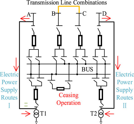
FIGURE 1. Topology of 220 kV side in a substation.
The substation’s 220 kV side structure, as illustrated in the figure, is a typical double-bus configuration. It is interconnected with the 220 kV transmission system through four incoming lines labeled A, B, C, and D. Additionally, it is linked to the low-voltage system via two main transformers, denoted as T1 and T2. When the 220 kV side of the substation undergoes a complete shutdown maintenance, the main busbar equipment within the grey area in the diagram goes out of operation. This indirectly leads to the disconnection of the main transformers T1 and T2 from the 220 kV system. During this period, it is possible to establish an internal power supply transfer path to enable the internal load of the substation to be supplied. By establishing power pathways on both sides of A and T1, as well as on both sides of D and T2, as shown in the diagram, it ensures the continuous supply of partial loads. The amount of power that the supply pathways can transmit is determined by the rated capacity of the lines and the distribution of the system’s power flows.
Besides, during the maintenance of the 220 kV side of the substation, the lines A, B, C, and D shown in Figure 1 are out of service. And various methods of interconnection can be employed to combine the transmission lines to stabilize the system network configuration. For instance, as illustrated in Figure 2, the diagram for line connection outside of the substation.
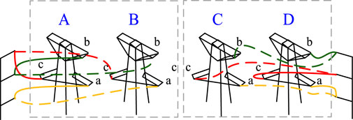
FIGURE 2. Diagram for line connection outside of the substation.
The common aspects between substation maintenance planning and transmission network planning include:
(1) In the investment planning phase, both require assessing the optimal connectivity and disconnection status of lines under constraint conditions. In the investment phase of transmission network planning, decision-makers often need to decide on the construction feasibility of existing transmission corridor lines (MA et al., 2015; LIU et al., 2018; Qian et al., 2018).However, in the investment phase of maintenance planning, decision-makers need to determine, based on the system’s topology after the substation’s components are out of operation, how to establish internal power pathways within the substation, as well as how to combine the remaining lines that are forced to shut down outside the substation. Since all feasible combinations of pre-established alternative power pathway options and the interconnection of external lines are known, the maintenance planning involves deciding the construction of different power pathways and whether to build specific line combinations, making it quite similar in form to transmission network planning.
(2) In the operational phase, both require calculating the system operating costs under constraint conditions. Whether it is transmission network planning or maintenance planning, both need to determine the optimal combination of unit operation and load shedding strategy to minimize the sum of unit operating costs and load shedding penalty loss costs.
(3) Both share similar network constraint conditions. Whether it is optimizing substation maintenance plans or transmission network planning, both need to satisfy comparable constraints related to power balance and variable boundary conditions (Mavalizadeh et al., 2014; Chen and Wang, 2016; Zhang and Conejo, 2018).
However, there are still certain differences between maintenance planning and transmission network planning, specifically including:
(1) In substation maintenance planning, decision-makers are more concerned with the safe and stable operation of the system during the maintenance period. At the same time, due to the significant power transmission tasks often borne by the 220 kV side of the substation, even with the establishment of internal power supply transfer paths, it can be challenging to ensure the transfer of the entire load.
(2) In addition to determining the external line connection form, substation maintenance planning also involves deciding on the optimal method for constructing internal power supply routes within the substation. Furthermore, substation maintenance plans have maintenance constraints (MC) that differ from those in transmission planning.
(3) In transmission network planning, investment cost primarily refers to the cost of line construction, and the planning typically considers longer timeframes, usually in terms of years. In maintenance planning, investment cost primarily refers to the operation and maintenance of transfer equipment and the temporary combination of lines. The maintenanceperiod is not excessively long, typically measured in weeks or months.
In summary, both maintenance planning and transmission network planning share many similarities in terms of optimization objectives and constraint conditions, yet they also exhibit distinct differences. Therefore, this paper is based on transmission network planning theory and takes into account the characteristics of maintenance planning to construct an optimization model for substation maintenance planning.
Assuming that the maintenance is carried out at substation located at node i, The power value carried by the transformer
Where
As mentioned above, the optimization objectives of the substation maintenance planning model can be divided into three categories. The first is unit operating costs, the second is investment costs, and the third is load shedding penalty costs that reflect the system’s reliability.
Since load shedding occurs during the operational phase and is determined in real-time, it is possible to combine the unit combination operating costs with the necessary load shedding penalty costs into a comprehensive operational cost. The investment cost of substation maintenance planning can be categorized into two types: one is the cost of reconstructing the transmission network and constructing in the substation, and the other is the cost associated with load shedding penalties imposed due to the necessary forced outages. The former includes the cost of shutting down external lines and the cost of constructing internal power supply transfer paths within the substation; The latter includes additional penalty costs due to load shedding caused by insufficient capacity and quantity of load transfer lines.
We define an integrated cost “C", encompassing investment-related load shedding penalties and margin-based rewards, to evaluate the transfer capability of different plans for the load carried by the substation during the investment phase. Its expression is presented in Eq. 3.
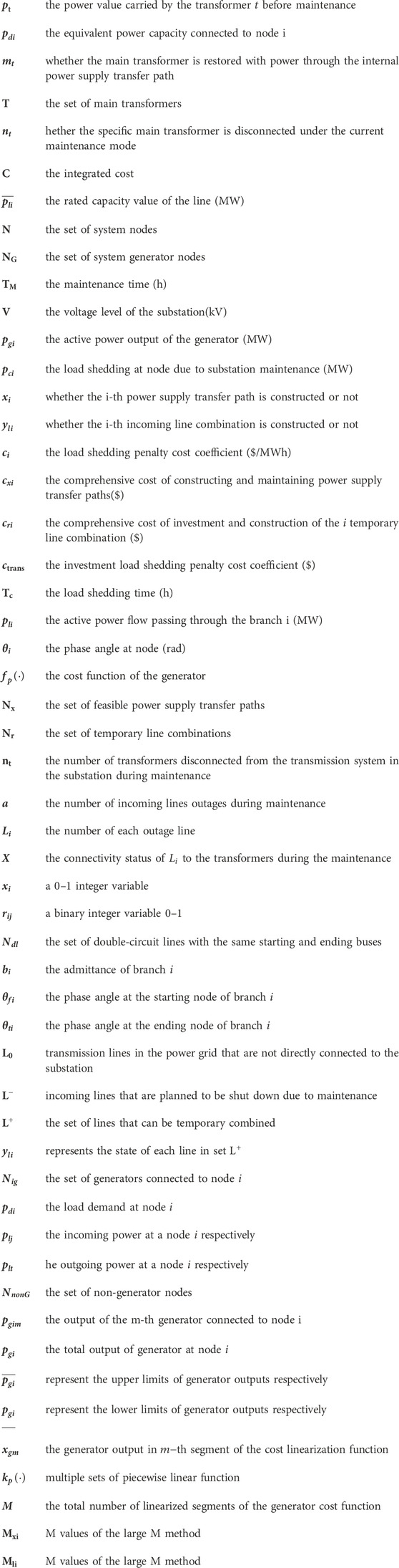
Where represents the rated capacity value of the line (MW),N represents the set of system nodes, represents the set of system generator nodes, represents the maintenance time (h),V represents the voltage level of the substation(kV).
The above equation consists of two cost components. The first component is the cost incurred due to load shedding during maintenance when the temporary transfer transformer capacity is insufficient. The reduced load is equal to the maximum capacity of the temporary transfer line minus the user load demand. The second component is the cost used to measure the capacity margin cost for different lines acting as transfer lines. This is defined as an incentive cost added to the investment cost in this paper.
Therefore, the objective function of load transfer planning model for equipment maintenance in the substation can be expressed as:
Where represents the active power output of the generator (MW), represents the load shedding at node due to substation maintenance (MW), represents whether the i-th power supply transfer path is constructed or not, represents whether the i-th incoming line combination is constructed or not, represents the load shedding penalty cost coefficient ($/MWh), represents the comprehensive cost of constructing and maintaining power supply transfer paths($), represents the comprehensive cost of investment and construction of the temporary line combination ($), represents the investment load shedding penalty cost coefficient ($), represents the load shedding time (h), represents the active power flow passing through the branch (MW), represents the phase angle at node(rad), represents the cost function of the generator, represents the set offeasible power supply transfer paths,
The above optimization objective is divided into three parts. The first three terms represent the investment costs of maintenance planning, including the construction cost of power transfer routes, the cost of line connections, and the investment-related system load shedding penalty and capacity reward costs; The fourth term represents the operating cost of the system’s generator unit; The fifth term represents the cost of load shedding during maintenance, reflecting the system’s reliability.
The operating cost of the generator units follows a quadratic function relationship with the generator output, as illustrated in Figure 3, the cost function for operating a generator unit.
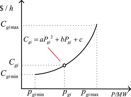
FIGURE 3. The cost function for operating a generator unit.
During the maintenance period, a total of
Let
The above equation indicates that the total number of constructed load transfer paths should be less than or equal to the total number of transformers.
Besides, the incoming lines of the substations can be stabilized through temporary combinations, resulting in a total of
Eq. 6 implies that the matrix is symmetric; Equations (7) and (8) implies that the sum of each row or each column in the connectivity matrix is not greater than 1, indicating that each line can be connected to at most one other line at the same time; Eq. 9 represents the constraint on the number of line connection combinations; In Equation 10,
In addition, the lines serving as load transfer paths during maintenance cannot be connected to other incoming lines, which following constraint:
The substations are directly connected to the transmission system, thus the maintenance planning model proposed in this paper also needs to comply with the operating constraints of the transmission system. Based on references (Samarakoon et al., 2001; LIU et al., 2021), the Network Constraints (NC) constraints for load transfer planning model are as follows.
The three equations represent the branch power flow balance equations for the transmission lines not directly connected to the substation, the incoming lines to the substation, and the new lines created through temporary combination respectively. Where
The relationship between
The
Eq. 19 represents the boundary constraint for branch power flows, Eq. 20 represents the boundary constraint for node phase angles, Eq. 21 represents the boundary constraint for generator outputs, and Eq. 22 represents the boundary constraint for node load shedding. Where
The equations (4)–(22) collectively constitute the optimization model for the load transfer planning model for equipment maintenance in the substation. To improve the efficiency of solving the model, the nonlinear objective and constraints in the above model need to be linearized.
The cost function of the generator is quadratic, we linearize this quadratic function using piecewise linearization methods. The generator output range is divided into multiple intervals, within each interval it is approximated that the generator unit operating cost is linearly related to the generator output, as shown in Figure 4, the linearized function for generator unit operating cost.
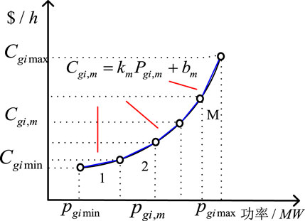
FIGURE 4. Linearized function for generator unit operating cost.
Using multiple sets of piecewise linear function
Where
Where
Eq. 11 is a nonlinear constraint. For the product
Based on the above formula, the linearized form of (11) can be obtained as follows:
Equations (13) and (14) contain the product of 0–1 integer variable and continuous variable, which belongs to nonlinear term. According to (Zhuo et al., 2020; Han et al., 2019), using the large M method, it can be transformed into the following linearized form:
Where,
The original nonlinear model is transformed into a mixed-integer linear programming (MILP) model. For this MILP model, the branch-and-bound algorithm can be employed to solve the problem. The detailed process of the branch-and-bound algorithm can be found in the literature (Gao et al., 2021).
To validate the proposed load transfer planning model, this study employs two cases based on the IEEE-RBTS6 node system and the IEEE-RTS79 system to examine the applicability of the model.
The original topology and parameters of the RBTS6 node system are presented in reference (Yang et al., 2022). This paper proposes a modification to the existing system. Assuming Bus 3 to represent the 220 kV side of a certain substation, adopting a double busbar configuration, and being connected to the low voltage level network through two main transformers, the modified RBTS-6 node system (System A) is illustrated in Figure 5, the topology of the system A.

FIGURE 5. Topology of the system A.
In Figure 5, the right half illustrates the original topology of the RBTS-6 node system, while the left half, enclosed by the dashed box, represents the primary bus configuration of Bus3. Incoming lines L1, L6, L4, and L5 carry power through transformers within the substation to supply the low-voltage system. L1 and L6 are double-circuit transmission lines on the same tower. When the entire substation undergoes a complete shutdown for maintenance, all four incoming lines are disconnected from the load at BUS3. The loads of the two transformers are equal.
In this case, the construction cost coefficient for each load transfer line is $300,000 per line. The temporary line connection cost is $2,000 per meter (including the cost of tower construction). The load penalty cost coefficient is $5,000 per MWh, The power loss due to the absence of constructed power transfer lines is set as $0.596 per kWh. The maintenance period is set as 30 days. Based on the parameters mentioned above, The following 5 maintenance strategies are analyzed:
1) Method 1: No maintenance measure is adopted.
2) Method 2: Constructing a power supply route within the substation without external line combination.
3) Method 3: Constructing a power supply route within the substation and performing external line combination.
4) Method 4: Constructing two power supply routes within the substation without performing external line combination.
5) Method 5: Constructing two power supply routes within the substation and performing external line combination.
The optimized results for the best planning scenarios are presented in the following Table 1:
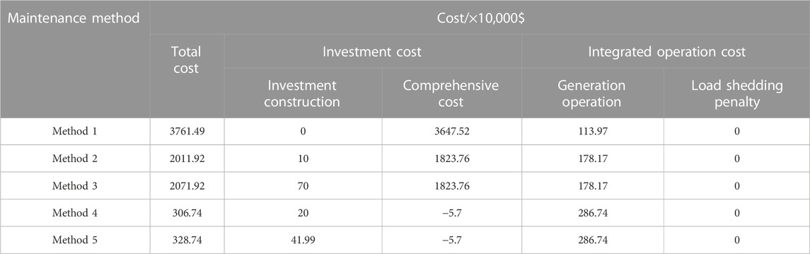
TABLE 1. Optimization results for maintenance plans in System A substation under four different shutdown methods.
The optimal topology diagrams corresponding to the above-mentioned strategies are depicted in the Figure 6, the optimal topology diagram:
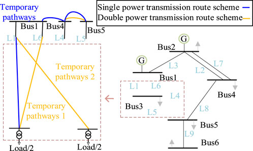
FIGURE 6. Optimal topology diagram.
When constructing multiple power paths, the total cost is much lower compared to constructing a single path or not constructing any, with a difference of nearly tenfold. This is mainly due to the significant cost of load loss during the maintenance period. Furthermore, when comparing Method 2 with Method 3, and Method 4 with Method 5, it can be observed that using external line connections actually leads to higher costs. This is because, regardless of whether external line connections are constructed or not, the system’s generation cost remains the same, while line connections add extra investment costs.
Comparing the power flow in the system before maintenance and during maintenance using methods 4 and 5, as shown in Figure 7, the comparison of power flow results between Method 4 and Method 5 in system A.
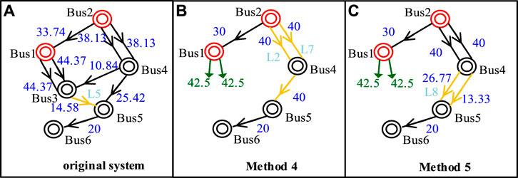
FIGURE 7. Comparison of power flow results between Method 4 and Method 5 in system A.
By connecting the lines as shown in figure (c), it can be observed that the connected lines share the power burden of L8, resulting in a reduction of about one-third in its power load. Therefore, though the method of connecting lines doesn't directly impact the system’s operational cost and adds extra investment cost, it enhances the system’s security in two ways: it resolves the long-term outage issue of the L4 and L5 lines; it alleviates the flow burden on L8, which enhances the transmission margin of the system.
In conclusion, during the maintenance of the substation, both the construction of load transfer lines and the temporary combination of incoming lines not only affect the initial investment and construction costs but also play a significant role in enhancing the system’s reliability and security.
The original topology and network parameters of the IEEE-RTS79 system are presented in reference (Kim et al., 2022). Based on the IEEE-RTS79 system, we assume that the node Bus21 is substation with a double-bus configuration, the power is transmitted to the system through two main transformers. The modified IEEE-RTS79 system (System B) is illustrated in Figure 8, the topology of the system B.
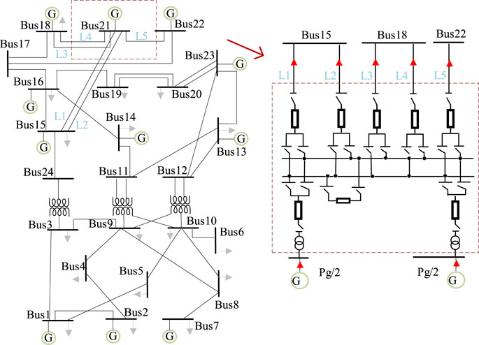
FIGURE 8. Topology of the system B.
In Figure 8, electrical power is transmitted through two transformers to 5 incoming lines marked L1-L5. When the substation undergoes a complete shutdown for maintenance, the external incoming lines are affected and shut down. The generating units at BUS21 in the system B lose its connection path to the system. As a result, the system experiences a shortfall in power supply, and it weakens the network architecture of the original system. Therefore, the maintenance plan for System B is analyzed using the load transfer planning model described in this paper. The parameters are the same as described in Section 3.1, the following 5 maintenance strategies are analyzed:
1) Method 1: Not adopting any maintenance measures
2) Method 2: Constructing a power supply route within the station without external line combination
3) Method 3: Constructing a power supply route within the station and performing external line combination
4) Method 4: Constructing two power supply routes within the station without performing external line combination
5) Method 5: Constructing two power supply routes within the station and performing external line combination
The optimized results for the best planning scenarios are presented in the Table 2:
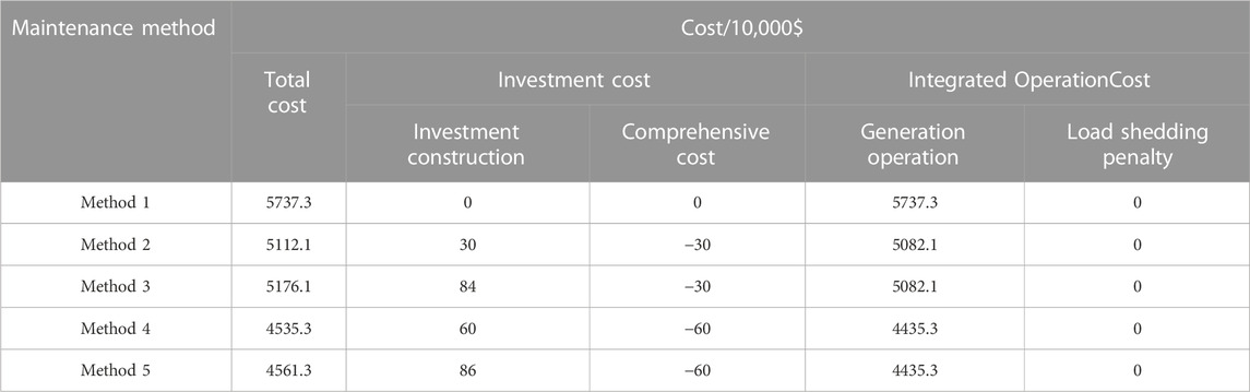
TABLE 2. Optimization results for maintenance plans in System B substation under four different shutdown methods.
The optimal topology structures for the above scenarios are shown in the following Figure 9, the optimal topology diagram:

FIGURE 9. Optimal topology diagram.
From Table 2, it can be seen that when multiple load transfer routes are constructed within the substation, the total cost is much lower compared to not constructing load transfer routes or constructing only one load transfer route. The main reason for this is that the operating costs of the connected generating units are lower within the station when there are multiple load transfer routes: in other words, the economic viability of a single generator producing a high power output is not as favorable as that of multiple generators producing lower power outputs.
In addition, by comparing Method 2 with Method 3 and Method 4 with Method 5 reveals that using external line connections actually results in higher costs for the system. This is because, regardless of whether external line connections are used or not, the system’s generation costs remain unchanged, while line connections introduce additional investment costs. The main reason for this phenomenon is the high generation capacity reserve in the RTS79 system. Even when considering the load demand at peak levels and the outage of generator at Bus21, the system still has surplus generation capacity, which is sufficient to ensure a balanced power supply. Simultaneously, the rated capacities of the transmission lines are very high, and there will not be issues of transmission congestion. Therefore, the external line connection will not affect generator outputs or improve overload of lines.
To validate the impact of incoming lines connection on the improvement of system load flow distribution, an analysis was conducted on the load flow distribution of the lines in System B under maintenance methods 4 and 5, respectively. The results are illustrated in the following Figure 10, the comparison of power flow results between Method 4 and Method 5 in system B.
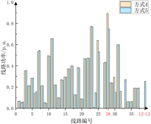
FIGURE 10. Comparison of power flow results between Method 4 and Method 5 in system B.
It can be observed that in the case of Method 4, the load in Line 28 approaches 0.9 p.u., which is close to its rated capacity. Based on the topology diagram shown in Figure 8, Line 28 is a transmission line located between BUS16 and BUS17. Under maintenance method 4, with the line between BUS15 and BUS21 out of service, leading to a significant increase in power transmission through Line 28. However, by connecting the lines L2 and L3, a new path is created between BUS15 and BUS18, which effectively reducing the load on Line 28. Therefore, under maintenance mode 5, Line 28 has a higher transmission margin, which improved the reliability of the system.
This study has established a load transfer planning model during the equipment maintenance in the substation. Drawing upon transmission network planning theory, an analysis has been conducted to highlight the similarities and differences between maintenance planning and transmission network planning. The study presents the optimization objectives, maintenance constraints, power balance constraints, and network operation safety constraints for the load transfer planning model. Furthermore, these constraints have been linearized to facilitate ease of solution. The analysis of case studies using IEEE-RBTS6 and IEEE-RTS79 demonstrates that:
(1) In the case of the IEEE-RTS6 system, compared to methods without constructing load transfer pathways and methods with the construction of a single load transfer pathway, the introduction of two load transfer pathways results in a reduction of 21% and 12% in the operational costs of generating units respectively. Furthermore, by implementing an internal load transfer pathway within the substation, it effectively mitigates economic losses caused by the load losses, leading to a noticeable enhancement in economic feasibility. Upon connecting external incoming lines, there is a slight increase in the cost of load transfer, but it simultaneously reduces the transmission power on the line with the highest load by 33%, thus improving the system’s safety and reliability.
(2) In case of the IEEE-RTS79 system, the construction of the load transfer pathway effectively prevents the increase in operating costs for the generators in the system caused by the shutdown of the power source directly connected the substation undergoing maintenance. Compared to methods without constructing load transfer pathways and methods with the construction of a single load transfer pathway, the introduction of two load transfer pathways results in a reduction of 91% and 84% in the operational costs of generating units respectively, which demonstrating a noticeable improvement in economic feasibility. Upon connecting external incoming lines, there is a slight increase in the cost of load transfer, but it simultaneously reduces the transmission power on the line with the highest load by 15%.
In conclusion, the model proposed in this paper can be applied to optimize load transfer planning during substation equipment maintenance. The case study results demonstrate that by constructing internal load transfer pathways within the substation and connecting incoming lines out of the substation, it is possible to effectively reduce the system’s economi
The raw data supporting the conclusion of this article will be made available by the authors, without undue reservation.
KZ: Conceptualization, Project administration, Writing–original draft. TW: Data curation, Formal Analysis, Writing–original draft. HZ: Funding acquisition, Investigation, Writing–original draft. HL: Methodology, Writing–original draft. AT: Project administration, Supervision, Writing–original draft. HY: Validation, Writing–original draft. JP: Visualization, Writing–original draft.
The author(s) declare financial support was received for the research, authorship, and/or publication of this article. This work is supported by the Key R&D Program of Hubei Province (2023BAB002); and the Science and technology project of State Grid Hubei Electric Power Co., Ltd. (52153223000A).
The authors declare that the research was conducted in the absence of any commercial or financial relationships that could be construed as a potential conflict of interest.
The authors declare that this study received funding from the Science and technology project of State Grid Hubei Electric Power Co., Ltd. (52153223000A). The funder had the following involvement in the study: the decision to submit it for publication.
All claims expressed in this article are solely those of the authors and do not necessarily represent those of their affiliated organizations, or those of the publisher, the editors and the reviewers. Any product that may be evaluated in this article, or claim that may be made by its manufacturer, is not guaranteed or endorsed by the publisher.
Bagen, B., Huang, D., and Fattal, K. (2019). Enhanced probabilistic approach for substation reliability assessment. IET Generation. Transm. Distribution 13 (12), 2488–2495. doi:10.1049/Q17iet-gtd.2019.0133
Chen, B., and Wang, L. (2016). Robust transmission planning under uncertain generation investment and retirement. IEEE Trans. Power Syst. 31 (6), 5144–5152. doi:10.1109/TPWRS.2016.2538960
Ding, M., and Feng, Y. Research on the modeling and algorithm to global generator and transmission maintenance scheduling. Proc. CSEE, 2004, (05): 22–27. doi:10.13334/j.0258-8013.pcsee.2004.05.004
Gao, S., Song, T. E., Liu, S., Zhou, C., Xu, C., Guo, H., et al. (2021). Joint optimization of planning and operation in multi-region integrated Energy systems considering flexible demand response. IEEE Access 9, 75840–75863. doi:10.1109/ACCESS.2021.3081798
Garcí a-Bertrand, R., and Mí nguez, R. Dynamic robust transmission expansion planning. IEEE Trans. Power Syst., 2017,32(4): 2618–2628. doi:10.1109/tpwrs.2016.2629266
Han, X., Qiang, S. I., Yu, C., Chen, Z., Wang, C., Luo, W., et al. (2019). Distribution network self-healing optimization method based on mixed-integer linear programming. Smart Grid 47 (06), 107–112+126. doi:10.3969/j.issn.1673-7598.2019.06.016
Kim, Y.-K., Lee, G.-S., Yoon, J.-S., and Moon, S.-I. (2022). Evaluation for maximum allowable capacity of renewable Energy source considering AC system strength measures. IEEE Trans. Sustain. Energy 13 (2), 1123–1134. doi:10.1109/TSTE.2022.3152349
Liu, D., Cheng, H., Jia, L., Zeng, P., Zhang, J., and Lu, J. Review and prospects of robust transmission expansion planning. Power Syst. Technol., 2019, 43(1): 135–143. doi:10.13335/j.1000-3673.pst.2018.1351
Liu, D., Lu, L., Cheng, H., Li, A., Gang, L., and Zhang, X. (2021). Transmission network planning method based on the generalized master-slave splitting theory and coordination with distribution networks. Proc. CSEE 41 (17), 5856–5866. doi:10.13334/j.0258-8013.pcsee.201322
Liu, Z., Yu, H., Wang, S., Shi, R., Wang, Z., and Luo, Y. (2018). Comprehensive transmission network planning, considering both operational efficiency and wind curtailment losses. Power Syst. Technol. 42 (03), 827–834. doi:10.13335/j.1000-3673.pst.2017.1354
Majidi-Qadikolai, M., and Baldick, R. (2016). Stochastic transmission capacity expansion planning with special scenario selection for integrating N-1 contingency analysis. IEEE Trans. Power Syst. 31 (6), 4901–4912. doi:10.1109/tpwrs.2016.2523998
Mavalizadeh, H., Ahmadi, A., and Heidari, A. (2014). Probabilistic multi-objective generation and transmission expansion planning problem using normal boundary intersection. IET Gener. Transm. &Distribution 9 (6), 560–570. doi:10.1049/iet-gtd.2014.0278
Ma, Y., Wang, W., and Wen, Q. (2015). Transmission network planning based on the chaotic search strategy and bat algorithm. Power Syst. Prot. Control 43 (15), 17–21. JournalArticle/5b3beda1c095d70f0099191a.
Qi, Z., Junjie, Q., Dahai, Y., et al. (2018). “Risk assessment for transmission network planning scheme based on conditional value-at-risk,” in 2018 8th International Conference on Power and Energy Systems (ICPES), Colombo, Sri Lanka, 21-22 December 2018, 49–53.
Qian, X., Fang, B., Zhou, L., Cheng, H., and Jia, L. Research on the embedding and transformation methods of loss-of-load probability constraints in transmission network planning models. Power Syst. Technol., 2018, 42(06): 1760–1768. doi:10.13335/j.1000-3673.pst.2017.2659
Samarakoon, H. M. D. R. H., Shrestha, R. M., and Fujiwara, O. (2001). A mixed integer linear programming model for transmission expansion planning with generation location selection. Int. J. Electr. Power & Energy Syst. 23 (4), 285–293. doi:10.1016/s0142-0615(00)00042-9
Sarantakos, I., Greenwood, D. M., Yi, J., et al. A method to include component condition and substation reliability into distribution system reconfiguration. Int. J. Electr. Power & Energy Syst., 2019, 109: 122–138. doi:10.1016/j.ijepes.2019.01.040
Wang, J., Chen, H., Zhang, Y., and Huang, H. Basic studies on risk management of power grid operation. South. Power Syst. Technol., 2015, 9(02): 1–8. doi:10.13648/j.cnki.issn1674-0629.2015.02.001
Yang, H., Zhang, K., and Tang, A. (2022). Risk assessment of main electrical connection in substation with regional grid safety constraints. IEEE Access 10, 27750–27758. doi:10.1109/ACCESS.2022.3157750
Zhang, X., and Conejo, A. J. (2018). Robust transmission expansion planning representing long-and short-term uncertainty. IEEE Trans. Power Syst. 33 (2), 1329–1338. doi:10.1109/tpwrs.2017.2717944
Zhang, H., Cheng, H., Zeng, L., Zhang, J., Lu, J., and Cong, L. (2017). Overview of transmission network expansion planning based on stochastic optimization. Power Syst. Technol. 41 (10), 3121–3129. doi:10.13335/j.1000-3673.pst.2017.1176
Zhuo, Z., Du, E., Zhang, N., Kang, C., Xia, Q., and Wang, Z. (2020). Incorporating massive scenarios in transmission expansion planning with high renewable Energy penetration. IEEE Trans. Power Syst. 35 (2), 1061–1074. doi:10.1109/TPWRS.2019.2938618
Keywords: maintenance of substation, 220 kV, transmission planning, reliability, linear
Citation: Zhang K, Wang T, Zhou H, Li H, Tang A, Yang H and Peng J (2023) Research on load transfer planning model for equipment maintenance in the substation. Front. Energy Res. 11:1290805. doi: 10.3389/fenrg.2023.1290805
Received: 08 September 2023; Accepted: 14 November 2023;
Published: 05 December 2023.
Edited by:
Mingfei Ban, Northeast Forestry University, ChinaReviewed by:
Xiaofei Wang, National Renewable Energy Laboratory (DOE), United StatesCopyright © 2023 Zhang, Wang, Zhou, Li, Tang, Yang and Peng. This is an open-access article distributed under the terms of the Creative Commons Attribution License (CC BY). The use, distribution or reproduction in other forums is permitted, provided the original author(s) and the copyright owner(s) are credited and that the original publication in this journal is cited, in accordance with accepted academic practice. No use, distribution or reproduction is permitted which does not comply with these terms.
*Correspondence: Aihong Tang, dGFoQHdodXQuZWR1LmNu
Disclaimer: All claims expressed in this article are solely those of the authors and do not necessarily represent those of their affiliated organizations, or those of the publisher, the editors and the reviewers. Any product that may be evaluated in this article or claim that may be made by its manufacturer is not guaranteed or endorsed by the publisher.
Research integrity at Frontiers
Learn more about the work of our research integrity team to safeguard the quality of each article we publish.