
95% of researchers rate our articles as excellent or good
Learn more about the work of our research integrity team to safeguard the quality of each article we publish.
Find out more
ORIGINAL RESEARCH article
Front. Energy Res. , 26 October 2023
Sec. Wind Energy
Volume 11 - 2023 | https://doi.org/10.3389/fenrg.2023.1285073
This article is part of the Research Topic Zero-emission Superconducting Techniques and Applications for Green Energy and Transportation Sectors View all 3 articles
 Hongyu Yang*Chao YuanYanan LiuRui Mei
A doubly fed induction generator (DFIG) configured for crowbar protection faces the following problems during low voltage ride through (LVRT): delayed input of crowbar protection and the difficulty in coordinating current limiting targets and DC voltage overrun with constant resistance rectification. A low voltage protection method of a DFIG based on a rotor-side double current limiting circuit is proposed. The rotor current characteristics during a fault are analyzed from a time domain perspective and used as a basis for resistance setting. The transient response characteristics of a resistive superconducting fault current limiter (RSFCL) are used for fast initial suppression of rotor currents. The adaptive crowbar resistance adjustment method is used to realize the coordinated consideration of current limiting and DC voltage non-overrun. The simulation results show that the proposed protection method effectively shortens the actual input time of the current limiting circuit and has good suppression ability for the rotor current at the early stage of fault. The adaptive and flexible resistance setting of the controllable crowbar circuit ensures that the DC voltage does not exceed the limit during the fault current limiting period, which helps improve the LVRT capability of doubly fed wind turbines.
Doubly fed induction generators (DFIGs) are widely used under the goals of China’s carbon peaking and carbon neutrality (De Souza et al., 2022). The rotor side of the DFIG induces a large electromotive force, which leads to rotor overcurrent when the grid voltage drops. The overcurrent in the rotor may cause damage to the inverter and generator and even lead to disconnection of the DFIG from the grid when more serious. Therefore, the short-circuit current and DC voltage on the rotor side are often used as important indicators to evaluate the LVRT capability of the DFIG (Okedu et al., 2012; Ren et al., 2022; Chen et al., 2021).
Oriented to the rotor current suppression during LVRT, the current research is centered on the control strategies and hardware circuits. As for control strategies, the LVRT performance of the DFIG is improved by using differential feedforward control of the stator current (Huilan et al., 2021). In Xiao et al. (2012) and Ding et al. (2021), a current limitation method has been proposed by controlling the magnetic chain. Although it does not rely on hardware circuits, it involves complex magnetic chain observation and separation techniques that are difficult to implement and not highly adaptable. Overall, it is difficult to effectively limit the rotor current by relying only on inverter control methods. Hardware circuits are still required to limit the current when the rotor current is at a higher level.
For more serious faults, the DFIG is usually equipped with an external circuit to suppress the rotor current, and one of the conventional methods used is crowbar protection (Camacho et al., 2017; Döşoğlu, 2020; Hamdan and Noureldeen, 2021). After a fault occurs, the short-circuit current is limited by blocking the rotor-side converter (RSC) and putting in a crowbar circuit. While limiting the current, the resistor also bears a part of the voltage. Although a large resistance can effectively suppress the rotor overcurrent, too large a crowbar resistance will cause the DC voltage to rise, and there will be the risk of voltage overrun (Pannell et al., 2010; Justo et al., 2015). The conventional method always has a fixed resistance setting, therefore the conventional crowbar protection is poorly coordinated and the objectives of the current limiting and avoiding DC overvoltage cannot be achieved simultaneously (Reddy and Saha, 2022). On the basis of conventional crowbar protection, there are some research devoted to the improvement of crowbar protection, such as the setting up of a resistance value for the crowbar. A method for implementing fault ride-through by the hierarchical input of protection circuits was proposed by Zhao et al. (2016). An LVRT scheme for the DFIG based on crowbar parallel dynamic resistance was proposed by Zhang and Jiang (2014). However, methods used by Zhao et al. (2016) and Zhang and Jiang (2014) result in longer investment time for parallel resistors, which is not conducive for rapid protection after a fault. An adaptive switching strategy for crowbar protection has been proposed by Tan et al. (2021). The neural networks are used to efficiently fit DFIG rotor current transient processes after resection. The application of this method in engineering practice remains to be verified. A new crowbar circuit structure was proposed by Yongqing et al. (2014), but the resistance setting value of the crowbar resistance was not specified. A new type of resistance series capacitive crowbar structure had been proposed by Zheng et al. (2012), but it is not easy to apply in practice. The crowbar protection solutions studied in the existing literature basically focus on performance optimization after the crowbar is put in, such as the adaptive resistance setting of the crowbar. They are useful for improving the LVRT performance and avoiding DC voltage overruns and have brought new solution ideas for the crowbar resistance setting. However, the assumptions of the aforementioned studies are overly ideal, that is, they assume that the crowbar resistor is put in at the moment of fault but ignore the fact that the crowbar is not actually put in instantaneously after a fault, there is a big difference with the actual response process.
In fact, according to the operating regulations of LVRT, the detection of the voltage drop (fault detection) is the basis of LVRT implementation, and there is a significant delay in the input of the actual crowbar protection. The conventional method is used to calculate the RMS value of the voltage through fast Fourier transform (FFT), which has a long calculation window. Thus, there is an obvious time delay (basically around 10 ms) in identifying faults and crowbar actions (Chakraborty and Maity, 2023). Some rapid fault detection methods have been proposed to facilitate the rapid implementation of LVRT. Fan and Liu (2012) used park transform to detect faults, but the method relies on filters, which may cause lag in the detection algorithm. Wavelet transform and Hilbert–Huang transform (HHT) methods were used to detect faults in Costa and Driesen (2012) and Hasan et al. (2020), respectively. Mathematical methods theoretically have faster detection speed, and the verification results show that the fault detection time is approximately 5 ms, but it is difficult to implement this in practice. The short-circuit current shows a decaying characteristic, and the current is maximum at the instant after the fault. However, due to the input delay of the crowbar resistor, the rotor current cannot be effectively suppressed at the early stage of the fault, which poses a serious threat to the inverter, which is also a problem at present. Although some of the aforementioned studies try to solve the delay of LVRT or crowbar protection input, they basically rely on complex mathematical methods, which have to be further tested for both practical engineering applications and implementation. Therefore, it is necessary to carry out further research on it and open up new ideas to solve the delay of the LVRT input.
Analogous to the current limiting objective of the DFIG and looking at system-level short-circuit current limiting measures, some valid studies can be found. At the system level, without changing the topology of the system, many scholars have investigated fault limiters. This is because short-circuit currents can be effectively suppressed by simply putting in a fault current limiter in the post-fault circuit, and this is especially true for resistive fault current limiters. This is the same basic logic as the DFIG input of crowbar resistors. Resistive superconducting fault current limiter (RSFCL) is usually used to limit short-circuit current in power systems. The current limiter can be considered a purely resistive element after a fault, which ultimately achieves the goal of current limitation. Bock et al. (2014) stated that RSFCL is an excellent means of limiting short-circuit currents, which has been verified. Although it is not directly applied to the current limitation of the DFIG, it opens up ideas for research in this work. Xi et al. (2019) analyzed the application of RSFCL in DC systems and showed a good current limiting effect. Jiang et al. (2021) also analyzed the application of RSFCL for reclosing of DC systems, and pointed out to its good current limiting characteristics. SE et al. (2019) connected RSFCL in series to the current limiting between the RSC and step-up transformer, which enhanced the LVRT capability of the DFIG by connecting the resistor in series, but the types of faults that can actually be coped with are not comprehensive. In summary, regarding the application of RSFCL in power systems, it is generally proved that the response is good, but its practical application to a DFIG is still relatively small. It is undeniable that the application of RSFCL in the power system has the possibility of migrating the application to the DFIG system. In particular, RSFCL has nearly transient response characteristics and the potential to shorten the delay of the traditional crowbar protection input.
It is not difficult to find that the existing studies on the adjustment of crowbar resistance ignore the fact of input delay, and the DFIG is still exposed to the risk of overcurrent at the instant of fault. While addressing the fault detection delay work, it is mostly difficult to implement, and the effectiveness is difficult to measure. The two parts (crowbar input delay and avoiding DC voltage overrun) are relatively independent and not well combined to form a perfect LVRT strategy. In order to effectively enhance the LVRT capability of the DFIG, it is expected that the current is limited quickly after a fault and guaranteed that the DC voltage will not overrun during the current limiting period. In this paper, a low voltage protection method of the DFIG based on a rotor side double current limiting circuit is proposed, which will address both of these problems from the point of view of the easiest engineering implementation. The research idea is shown in Figure 1. By putting in RSFCL at the instant of the fault, the huge increase in current at the beginning of the fault is suppressed effectively. Different crowbar resistance values are adaptively put in depending on the rotor current and the DC voltage restraint, and DC voltage overrun is prevented. A simulation verification was carried out in PSCAD. The effectiveness of the DFIG low voltage protection scheme proposed in this article is verified.
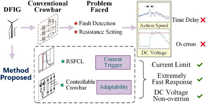
FIGURE 1. Research ideas and problems to be solved.
The setting of the crowbar resistance value depends on the rotor current, and to more accurately characterize the faults of the DFIG, the dynamic mathematical model of the rotor is first analyzed. In general, traditional crowbar resistors are calibrated to the maximum short-circuit current or to when a three-phase symmetrical fault occurs. There are two problems with this method of setting: first, three-phase short circuits occur infrequently and more asymmetrical faults occur. Second, the rectification is too harsh and the resistance value is not flexible, which may lead to problems such as DC voltage overrun.
Therefore, in conjunction with the practical situation and the methodology proposed in this work, the focus will be on analyzing the DFIG fault characteristics during asymmetric faults.
Assuming that the grid voltage falls asymmetrically due to a fault at time
where
Due to the inability to mutate the stator chain after failure and considering that the stator inductance (
where
It can be seen that there are three voltage components in the DFIG under asymmetrical faults, corresponding to which there are three current components. Therefore, the superposition theorem can be used to find the rotor current during fault.
The rotor current component during an asymmetrical fault under the action of the three voltage-forcing components is expressed by Eqs. 3–5:
Since the fault current at moment
In summary, the rotor current during an asymmetrical fault is expressed as
It can be seen that the asymmetrical fault current components are complex, and the influencing factors of the current are many and strongly coupled. Due to the negative sequence component in the rotor voltage, which leads to the DFIG rotor current component also containing a negative sequence component, the magnitude of the fault current amplitude is related to the actual fault voltage drop degree and turndown rate.
The resistive superconducting fault current limiter (RSFCL), as a kind of fault current limiting device, has zero resistance value when normal and a high resistance state after being triggering. Because of its good current limiting performance and resistance characteristics (Jiang et al., 2021), it has been applied in the field of power systems in recent years (Khatibi et al., 2022). Assuming the triggering current of RSFCL is Ic, its resistance characteristics can be represented as
where
The resistance characteristic corresponding to Eq. 8 is shown in Figure 2. Because of the very short trigger time, RSFCL can generally be considered to conduct transiently during a fault, and this characteristic has the potential to compensate for the delay in the input of the crowbar resistor.
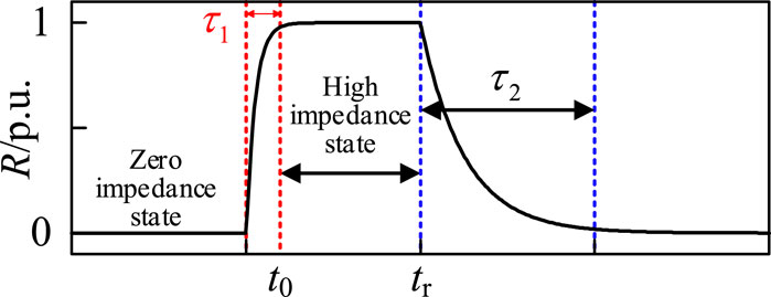
FIGURE 2. Resistance characteristics of RSFCL.
With reference to the application scenario of RSFCL in the power grid, the aforementioned analysis shows that it is feasible to apply RSFCL to the DFIG current limiting circuit, and its advantages can be summarized as follows:
1) The transient response characteristics of RSFCL compensate for the delay problem of the traditional crowbar input and limit the rotor overcurrent at the initial stage of faults.
2) No interference with the normal operation of the system. Under triggering current Ic, RSFCL exhibits zero impedance characteristics, and its impact on the original system is basically negligible.
The rotor current characteristics during faults vary depending on the degree of voltage drop, and it is hoped that the current limiting circuit will be adaptive to the actual fault current. Combining RSFCL transient response characteristics and multi-scenario current limiting objectives, a double current limiting circuit scheme with RSFCL and a controllable crowbar resistor is proposed. The topology is shown in Figure 3.
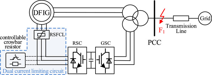
FIGURE 3. Double current limiting circuit topology.
The double current limiting circuit is constructed around the general control objective: limiting the rotor overcurrent to within 1.6 times the rated current. RSFCL is connected in series to the rotor circuit to compensate for the put-in time delay of crowbar resistance. Specifically, the double current limiting circuit operates as follows:
1) Non-serious overcurrent scenarios. It is expected that RSFCL can limit the rotor overcurrent to 1.6 times the rated current target. More importantly, RSFCL can be put into current limiting at the near-instant of fault.
2) Serious overcurrent scenarios. In this case, the current limiting ability of RSFCL may be insufficient, and the controllable crowbar resistor input for further current limit. At this stage, the controllable crowbar resistor is mainly further harmonized with the goal of current limiting and DC voltage non-overrun.
The RSFCL trigger current Ic should be set to meet rapid basic suppression of the rotor overcurrent. Ic can be set to be greater than the maximum fault current on the rotor side of the DFIG in the event of a single-phase fault on the transmission line. Ic is given by
where
For the resistance setting of RSFCL, consideration should be given to minimizing the dependence on crowbar resistance in scenarios where the rotor overcurrent is not severe. The resistance of RSFCL can be set according to the extreme condition of a single-phase grounding fault accompanied by a system voltage drop of 50%. Extreme refers to the degree of voltage drop, not to the type of fault.
In the event of a single-phase short-circuit ground fault in the grid, the stator three-phase voltage is expressed as
where
When RSFCL carries out a preliminary current limit, the current limiting circuit exists as
To solve for the value of
The controllable crowbar circuit is shown in Figure 4. The switching of R2 and R3 is controlled by two IGBTs, and the resistance value of the input circuit can be equivalently changed by changing the duty ratio of the IGBT. The specific parameters of the IGBT are shown in Table 1, which are also the parameters of the simulation model described in Section 4.
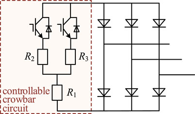
FIGURE 4. Implementation of the controlled crowbar circuit.
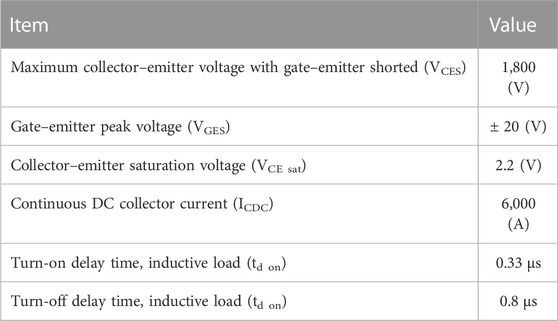
TABLE 1. Parameters of the switches IGBTs.
RSFCL and crowbar bar resistor inputs form a double current limiting circuit and exists as
According to the control objectives, it is generally believed that the peak current value on the rotor side is less than 1.6 times the rated value, and the maximum crowbar resistance
where
By solving Eq. 12 to get the value of R1, R2, R3 can realize the setting of crowbar resistance.
In addition to current limiting, controllable crowbar circuits should avoid DC voltage overruns during the current limiting process. For this consideration, during the fault period, the rotor current
where
According to Eq. 13, by changing the duty ratio of H1 and H2 of the two IGBTs, the corresponding crowbar resistance values are applied to suppress rotor overcurrent.
Based on the aforementioned analysis, it can be seen that RSFCL can compensate for the put-in time delay of the crowbar circuit. The resistance setting of controllable crowbars is more coordinated with multiple goals. Combining the aforementioned two characteristics, the control strategy of the DFIG double current limiting circuit is constructed in Figure 5.
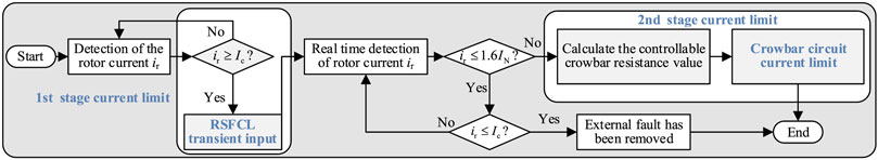
FIGURE 5. Control strategy of the double current limiting circuit.
To verify the applicability of the proposed strategy, a 5 MW DFIG simulation model was built in PSCAD, as shown in Figure 3, and the DFIG was connected to the grid via step-up transformers. The other parameters of the DFIG are listed in Table 2. The DFIG operates in constant power factor mode, and the power factor is set to 1, only active power is output during steady-state operation. For steady-state operation, the DFIG uses a dual closed-loop control strategy: an outer power loop and an inner current loop. The control is realized by PI session, and RSC uses the grid voltage directional vector control method (Zhu et al., 2015; Bekiroglu and Yazar, 2022). We assume that a fault occurs at the point of common connection (PCC) at 2 s, with a fault duration of 0.1 s. After the fault, it is triggered according to the fault threshold and switched to LVRT control, which means the crowbar is put in. It should be noted that the relevant protection configurations, operation control methods, and control parameters in the model are set according to the actual project. Therefore, the model can accurately reflect the problems of conventional crowbar protection and, at the same time, verify the effectiveness of the strategy proposed in this work.
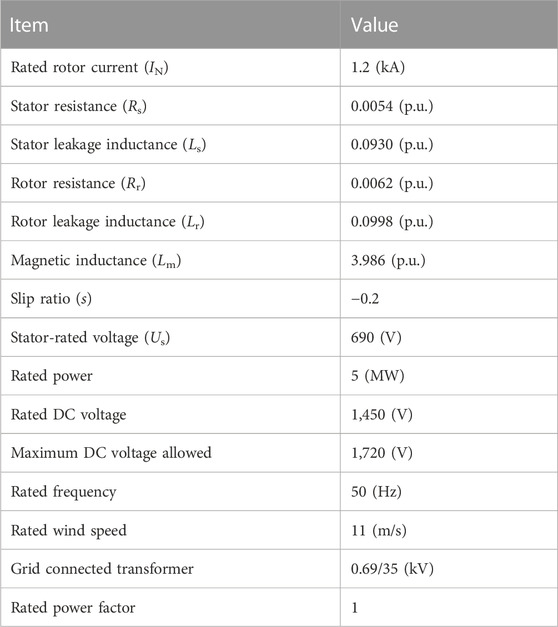
TABLE 2. Parameter of DFIG.
The initial values RSFCL = 0.21 Ω, R1 = 0.302 Ω, R2 = 0.168 Ω, R3 = 0.197, and Ic = 2.6 kA are selected.
AG, AB, ABG, and ABC faults are carried out as examples. The faults are all set at PCC, and the rotor current is analyzed.
According to the theoretical analysis provided in Section 2, the size of the rotor fault current is determined by the type of fault and the depth of voltage drop, with a sudden increase and decaying trend after the fault, which is verified by Figure 6. The rotor current during AG faults is the smallest among all types of faults (Figure 6A) and is essentially equal for AB and ABG faults (Figures. 6B, C). While during three-phase fault, although there is no additional negative sequence component, due to the maximum degree of grid voltage drop, the rotor overcurrent is the most serious and the maximum current is approximately 1.1 times the two-phase fault (Figure 6D).
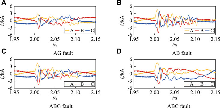
FIGURE 6. Rotor current at different types of faults. (A) AG fault. (B) AB fault. (C) ABG fault. (D) ABC fault.
In order to ensure the current limiting effect, the crowbar resistor is usually set according to the maximum overcurrent, that is, the three-phase fault corresponding to Figure 6D. The traditional method of the crowbar resistance setting is poorly coordinated, which may have a better current limiting effect, but the DC voltage will probably exceed the limit. DC voltage that overruns under conventional protection will be presented in comparison in Section 4.3.
This section verifies the action characteristics of the crowbar protection when different types of faults occur at PCC. Figure 7 shows the phase-A rotor current waveform, t0 is the time of fault, and t1 is the actual input time of the crowbar (the same below). As the severity of the fault increases (reflected in higher rotor overcurrent), the actual crowbar protection protective action time will be shorter, but not instantaneous.

FIGURE 7. Traditional crowbar protection action characteristics. (A) Rotor current with the AG fault. (B) Rotor current with the ABG fault. (C) Rotor current with the ABC fault.
In the case of AG fault, the crowbar protection delays the action by 8.1 ms; in the ABG fault, the crowbar protection delays the action by approximately 5 ms; and in the ABC fault, the crowbar protection delays the action by approximately 4.2 ms. Non-serious faults correspond to longer crowbar action times than do the serious one. This delay essentially limited by the control system’s detection of the fault is actually related to the type of fault, and different fault types have different delay input characteristics. From the short-circuit current characteristics, it can be seen that the current shows a decaying characteristic, and the short-circuit current is maximum at the instant after the fault. However, due to the input delay of the crowbar resistor, the rotor current cannot be effectively suppressed at the early stage of the fault, which poses a serious threat to the inverter, which is also a problem at present. In actual operations, single-phase faults occupy a larger proportion, and it is more important to face the problem as it is difficult to effectively suppress the overcurrent at the early stage of faults in weak fault scenarios.
The AG fault is set in this section, the voltage at PCC, rotor current, and DC bus voltage are shown in Figure 8, where t0 is the fault time and t2 represents the time of completion of RSFCL inputs.
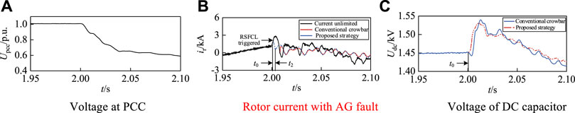
FIGURE 8. Double current limiting circuit operating characteristics for non-serious fault. (A) Voltage at PCC. (B) Rotor current with AG fault. (C) Voltage of DC capacitor.
In Figure 8A, the bus voltage drops by approximately 40%, and the drop is relatively slow. In the 2.7 ms after the fault when the RSFCL is input, the first stage of transient current limiting is completed, which satisfies t2 − t0 = 2.7 ms. Although this work emphasizes the transient conduction of RSFCL, Figure 8B shows that there is a delay of approximately 2.7 ms during AG fault for the following reasons: first, there is a time constant A (0.8–1 ms) for RSFCL conduction, which is ignored in the analysis in Section 3.1. Second, a short delay is required for the rotor current to develop to Ic. After RSFCL acts, it approximately reduces by 66.7% when compared to the traditional crowbar input time of 8.1 ms, which helps limit the short-circuit current quickly in the early stage of the fault.
As for the voltage of the DC capacitor, in the case of non-serious faults, only RSFCL limits the current, and its resistance is not rectified as harshly as the traditional crowbar rectification. The DC voltage response shown in Figure 8C exhibits two characteristics while meeting the current limiting objective: first, the rapid response, and second, the DC voltage with RSFCL smaller than that with traditional crowbar. The second characteristic becomes more obvious as the severity of the fault increases, which is analyzed in the next section. It should be noted that in considering that the DFIG is generally configured with crowbar protection and rarely without it, the main focus in Figure 8C is to compare the DC voltage of the proposed scheme and the conventional one. The same is true for the serious fault in Section 4.3.2.
The ABC fault set in this section is shown in Figure 9A; the bus voltage drops by approximately 80%, and the voltage drop is fast, with rapid fault development. According to the double current limiting circuit proposed in this work for current limiting, the rotor current waveform is shown in Figure 9B, where ① and ② are the fault moment and time when RSFCL is put into completion, respectively. While RSFCL works, the action time is also shortened by approximately 30%, the rotor current is effectively suppressed at the beginning of the fault, and there is an obvious advantage in the speed of current limiting when compared with the traditional crowbar method. It means that RSFCL can shorten the action time by at least 30% more than the conventional crowbar protection in the early stages of fault, thereby effectively suppressing the huge increase in rotor current in the early stages of the fault.
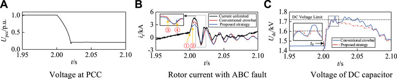
FIGURE 9. Double current limiting circuit operating characteristics for serious fault. (A) Voltage at PCC. (B) Rotor current with ABC fault. (C) Voltage of DC capacitor.
As the fault develops, only RSFCL cannot meet the current limiting objective. Therefore, at moment ③, the crowbar circuit in the double current limiting circuit is put into operation. At moment ④, the controlled crowbar circuit adjusts the resistance value for the first time to ensure that the DC capacitor voltage does not exceed the limit.
The DC capacitor is rated at 1.45 kV, and the maximum voltage allowed is 1.72 kV. Under severe ABC fault, DC voltage overruns occur with conventional crowbar protection, as shown in Figure 9C. By contrast, when using the double current limiting circuit proposed in this work, the crowbar resistance is adaptively adjusted under the DC voltage constraint of Eq. 13 to ensure that the DC voltage does not exceed the limit. After the double current limiting circuit is input, the rotor current is gradually reduced. The controllable crowbar resistor lowers the DC voltage by reducing the input resistance value, which further avoids the secondary voltage overrun. The double current limiting circuit has obvious advantages in suppressing the DC voltage overrun.
To ensure that DFIGs are not cut off from the grid during a fault, DFIGs are often configured with crowbar protection to enhance their LVRT capability. However, conventional crowbar protection configurations face the two following major problems: i) there is a delay in the action of crowbar protection triggered by the current threshold. It is difficult to effectively suppress the short-circuit current that increases in the initial period after a fault, which threatens the safe operation of the rotor and converter. ii) The current after a fault shows a tendency to decay, but the initial value of the fault current is closely related to the fault type. Therefore, the constant resistance of the crowbar is weakly adaptable to different fault types and may face the risk of DC voltage overrun. To address these problems, this work proposes a low voltage protection method of DFIG based on the rotor-side double current limiting circuit. After theoretical analysis and simulation verification, the following conclusions are arrived at:
1) The proposed RSFCL current limiting scheme can shorten the input time of the current limiting resistor and effectively limit the rotor overcurrent at the early stage of the fault. This scheme effectively fills the gap of current limiting measures in the early stage of failure. The fast response of the current limiting strategy avoids the impact of large currents on the rotor and converter.
2) The controllable crowbar resistor effectively improves the current limiting circuits’ resistance value setting problem. DC voltage constraints are constructed to dynamically adjust the resistance of the current limiting circuit to avoid the risk of DC voltage overrun and complete the second stage of current limiting.
The low voltage protection method of DFIG based on the rotor side double current limiting circuit proposed in this work is good for different fault types. It is well adapted for severe or non-severe faults. Along with the occurrence of faults, the proposed protection scheme responds quickly, which ultimately reduces the blocking time of RSC and improves the LVRT performance of the DFIG.
The original contributions presented in the study are included in the article/Supplementary Material; further inquiries can be directed to the corresponding author.
HY: methodology, visualization, manuscript writing–original, and manuscript writing–review and editing. CY: project administration, supervision, and manuscript writing–review and editing. YL: formal, investigation, analysis and manuscript writing–review and editing. RM: resources, software, validation, and manuscript writing–review and editing.
Jiangsu Frontier Electric Technology Co. Ltd. The funder had the following involvement in the study: project administration, research, authorship, and/or publication of this article.
This article has been strongly supported by Jiangsu Frontier Electric Technology Co. Ltd. The authors would like to express their sincere thanks for it.
Authors HY, CY, YL, and RM were employed by Jiangsu Frontier Electric Technology Co. Ltd.
The remaining authors declare that the research was conducted in the absence of any commercial or financial relationships that could be construed as a potential conflict of interest.
All claims expressed in this article are solely those of the authors and do not necessarily represent those of their affiliated organizations, or those of the publisher, editors, and reviewers. Any product that may be evaluated in this article, or claim that may be made by its manufacturer, is not guaranteed or endorsed by the publisher.
Bekiroglu, E., and Yazar, M. D. (2022). MPPT control of grid connected DFIG at variable wind speed. Energies 15 (9), 3146. doi:10.3390/en15093146
Bock, J., Hobl, A., Schramm, J., Krämer, S., and Jänke, C. (2014). Resistive superconducting fault current limiters are becoming a mature technology. IEEE Trans. Appl. Supercond. 25 (3), 1–4. doi:10.1109/tasc.2014.2364916
Camacho, A., Castilla, M., Miret, J., De Vicuna, L. G., and Guzman, R. (2017). Positive and negative sequence control strategies to maximize the voltage support in resistive–inductive grids during grid faults. IEEE Trans. Power Electron. 33 (6), 5362–5373. doi:10.1109/tpel.2017.2732452
Chakraborty, A., and Maity, T. (2023). Integrated control algorithm for fast and accurate detection of the voltage sag with low voltage ride-through (LVRT) enhancement for doubly-fed induction generator (DFIG) based wind turbines. Control Eng. Pract. 131, 105393. doi:10.1016/j.conengprac.2022.105393
Chen, S., Yao, J., Pei, J., Liu, Y., Liu, R., Huang, S., et al. (2021). Transient stability analysis and improved control strategy for DC-link voltage of DFIG-based WT during LVRT. IEEE Trans. Energy Convers. 37 (2), 880–891. doi:10.1109/tec.2021.3126855
Costa, F. B., and Driesen, J. (2012). Assessment of voltage sag indices based on scaling and wavelet coefficient energy analysis. IEEE Trans. Power Deliv. 28 (1), 336–346. doi:10.1109/tpwrd.2012.2218626
De Souza, V. R. F., Barros, L. S., Costa, F. B., and Junior, G. P. D. S. (2022). Doubly fed induction generator low voltage ride through improvement through modular multilevel converter. IEEE Access 10, 57914–57929. doi:10.1109/access.2022.3178960
Ding, C., Chen, Y., and Nie, T. (2021). LVRT control strategy for asymmetric faults of DFIG based on improved MPCC method. IEEE Access 9, 165207–165218. doi:10.1109/access.2021.3135574
Döşoğlu, M. K. (2020). Crowbar hardware design enhancement for fault ride through capability in doubly fed induction generator-based wind turbines. ISA Trans. 104, 321–328. doi:10.1016/j.isatra.2020.05.024
Fan, Z., and Liu, X. (2012). “A novel universal grid voltage sag detection algorithm,” in 2012 Power Engineering and Automation Conference, Wuhan, China, 18-20 September 2012 (IEEE), 1–4.
Hamdan, I., and Noureldeen, O. (2021). An overview of control method with various crowbar techniques of wind turbines during power system faults. SVU-International J. Eng. Sci. Appl. 2 (1), 35–45. doi:10.21608/svusrc.2021.80571.1010
Hasan, S., Muttaqi, K. M., and Sutanto, D. (2020). Detection and characterization of time-variant nonstationary voltage sag waveforms using segmented Hilbert–Huang transform. IEEE Trans. Industry Appl. 56 (4), 1–4574. doi:10.1109/tia.2020.2982850
Huilan, J., Shaohui, W., and Yanqi, J. (2021). Low voltage ride-through compound control strategy of doubly-fed induction generator based on stator current differential feedforward control. High. Volt. Eng. 47 (1), 198–204. doi:10.13336/j.1003-6520.hve.20200402002
Jiang, Z., Yu, Z., Zhou, Y., Liu, S., Li, X., and Pan, R. (2021). Application of resistance SFCL in MTDC grid with reclosing protection strategy. IEEE Trans. Appl. Supercond. 31 (8), 1–5. doi:10.1109/tasc.2021.3118317
Justo, J. J., Mwasilu, F., and Jung, J. W. (2015). Doubly-fed induction generator based wind turbines: a comprehensive review of fault ride-through strategies. Renew. Sustain. energy Rev. 45, 447–467. doi:10.1016/j.rser.2015.01.064
Khatibi, M., Jalilzadeh, S., Hussain, A., and Haider, W. (2022). A PSO-based approach for optimal allocation and sizing of resistive-type SFCLs to enhance the transient stability of power systems. Electronics 11 (23), 3980. doi:10.3390/electronics11233980
Okedu, K. E., Muyeen, S. M., Takahashi, R., and Tamura, J. (2012). Wind farms fault ride through using DFIG with new protection scheme. IEEE Trans. Sustain. energy 3 (2), 242–254. doi:10.1109/tste.2011.2175756
Pannell, G., Atkinson, D. J., and Zahawi, B. (2010). Minimum-threshold crowbar for a fault-ride-through grid-code-compliant DFIG wind turbine. IEEE Trans. Energy Convers. 25 (3), 750–759. doi:10.1109/tec.2010.2046492
Reddy, K., and Saha, A. K. (2022). A heuristic approach to optimal crowbar setting and low voltage ride through of a doubly fed induction generator. Energies 15 (24), 9307. doi:10.3390/en15249307
Ren, J., Wang, Y., Zheng, Z., Xiao, X., Zou, Y., Zong, Y., et al. (2022). Signature POWIs for DFIG under LVRT conditions: analysis, experiments and recommendations. Int. J. Electr. Power and Energy Syst. 136, 107622. doi:10.1016/j.ijepes.2021.107622
Se, A. W., Alaboudy, A. H. K., and Azmy, A. M. (2019). “Comparison between outer crowbar and RSFCL for LVRT capability enhancement of wind turbines conversion system,” in 2019 21st International Middle East Power Systems Conference (MEPCON), Cairo, Egypt, 17-19 December 2019 (IEEE), 884–889.
Tan, A., Wu, Y. Y., Wang, C. Q., and Li, F. Y. (2021). Adaptive switching strategy for a wind turbine crowbar based on the guarantee of low voltage ride-through capability. Power Syst. Prot. Control 49 (18), 98–109. doi:10.19783/j.cnki.pspc.201231
Xi, X., Gao, X., Huang, W., Li, S., Zhao, Y., and Lv, C. (2019). “Application analysis of resistor superconducting fault current limiter in MMC-HVDC system,” in 2019 IEEE Sustainable Power and Energy Conference (iSPEC), Beijing, China, 21-23 November 2019 (IEEE), 2260–2264.
Xiao, S., Yang, G., Zhou, H., and Geng, H. (2012). An LVRT control strategy based on flux linkage tracking for DFIG-based WECS. IEEE Trans. Industrial Electron. 60 (7), 2820–2832. doi:10.1109/tie.2012.2205354
Yongqing, M., Yu, W., and Xifan, W. (2014). Accurate calculation of DFIG transient performance and parameters optimization of Crowbar circuit. Automation Electr. Power Syst. 38 (8), 23–29. doi:10.7500/AEPS20130818001
Zhang, M., and Jiang, H. L. (2014). Adaptive low voltage ride-through of doubly-fed induction generators based on crowbar with a parallel dynamic resistor. Trans. China Electrotech. Soc. 29 (2), 271–278. doi:10.19595/j.cnki.1000-6753.tces.2014.02.033
Zhao, H., Tang, H., Zhang, W., and Wen, W. L. (2016). Transient characteristics research and integrated control strategy of DFIG for zero voltage ride through. Power Syst. Technol. 40 (5), 1422–1430. doi:10.13335/j.1000-3673.pst.2016.05.019
Zheng, Z., Yang, G., and Geng, H. (2012). Short circuit current analysis for DFIG-based wind generation system with crowbar protection under grid faults. Electr. Power Autom. Equip. 32 (11), 7–15.
Keywords: doubly fed induction generator, low voltage ride through, double current limiting circuit, resistive superconducting fault current limiter, resistance setting
Citation: Yang H, Yuan C, Liu Y and Mei R (2023) Low voltage protection method of DFIG based on rotor-side double current limiting circuit. Front. Energy Res. 11:1285073. doi: 10.3389/fenrg.2023.1285073
Received: 29 August 2023; Accepted: 11 October 2023;
Published: 26 October 2023.
Edited by:
Joshuva Arockia Dhanraj, Hindustan Institute of Technology and Science, IndiaReviewed by:
Kenneth E. Okedu, Melbourne Institute of Technology, AustraliaCopyright © 2023 Yang, Yuan, Liu and Mei. This is an open-access article distributed under the terms of the Creative Commons Attribution License (CC BY). The use, distribution or reproduction in other forums is permitted, provided the original author(s) and the copyright owner(s) are credited and that the original publication in this journal is cited, in accordance with accepted academic practice. No use, distribution or reproduction is permitted which does not comply with these terms.
*Correspondence: Hongyu Yang, eWh5MDAxMTAwQDEyNi5jb20=
Disclaimer: All claims expressed in this article are solely those of the authors and do not necessarily represent those of their affiliated organizations, or those of the publisher, the editors and the reviewers. Any product that may be evaluated in this article or claim that may be made by its manufacturer is not guaranteed or endorsed by the publisher.
Research integrity at Frontiers
Learn more about the work of our research integrity team to safeguard the quality of each article we publish.