 Jun Chen
- College of Electrical Engineering and Control Science, Nanjing Tech University, Nanjing, China
Aiming at the integrated energy microgrid, an important part of the energy internet, this paper constructs a multi-energy storage system optimization configuration model of the integrated energy microgrid in an independent mode, and proposes a configuration method that includes the rated power and capacity of the storage system and the heat storage system. The storage system model includes the estimation of battery life during heating and non-heating periods. The model takes economy as the index, and considers the relevant constraints of thermoelectric coupling of thermoelectric units, including thermal and electrical balance, unit climb, energy storage system and self-sufficiency probability, etc., and uses a The bacterial colony chemotaxis (BCC) algorithm model based on unit output and energy storage system power distribution strategy to solve the problem. The operation characteristics of cogeneration units equipped with energy storage system are discussed. The results show that the proposed multi-energy storage system configuration method has significant economic and environmental benefits in both heating and non-heating periods, and promotes the uptake of wind power.
1 Introduction
With the gradual depletion of traditional fossil energy and the increasingly serious environmental problems and global warming, vigorously developing low-carbon new energy represented by wind and light, and improving the penetration rate of renewable energy in the existing power grid has become one of the important ways to solve the above problems. As a result, the concept of energy Internet proposed by Jeremy Rifkin has received wide attention (Sezgin, 2018). The integrated energy micro network that can be applied to isolated islands, urban and rural residential areas, factories, remote areas away from the main network and other areas will become an important part of the energy Internet, and will become one of the trends in the development of the energy system in the future (Shiming et al., 2010). The concept of integrated energy micro grid is developed from the concept of micro grid, which generally includes four forms of energy: cold, heat, electricity and gas. All energy supply equipment sources in the region are integrated and dispatched using Internet of Things technology and information technology, so as to achieve the effect of optimizing energy supply for regional cold and hot electric loads and improving energy utilization efficiency (Pratama et al., 2017; Chen et al., 2016).
However, renewable energy represented by wind and light has strong intermittent and random volatility, which often leads to the generation of wind and light abandonment. Especially during heat supply, the operation mode of “power is determined by heat” of cogeneration units will reduce the peak shaving capacity of the entire microgrid, and even cause a lot of “wind abandonment” (Sadeghian et al., 2020). In order to absorb renewable energy and enhance the flexibility of the microgrid, we have introduced an energy storage system that can be used for multi energy storage in the microgrid.
The storage function of energy is called energy storage, mainly in the form of electricity storage, heat storage, gas storage and composite energy storage (P2G, liquid hydrogen SMES, etc.) (Marc et al., 2010). This paper mainly discusses two types of energy storage systems: electric storage and thermal storage. The promotion of microgrid technology research makes the research on power storage technology very sufficient. The electric energy storage technology can be used to suppress the short-term power fluctuation of renewable energy power generation, track the output of the dispatching plan, improve the power quality of renewable energy power generation connected to the grid, meet the flexible access of new energy to optimize the load, cut the peak and fill the valley, improve the system’s self-regulating ability, achieve load management and obtain economic benefits (Kousksou et al., 2014). A large number of scholars have studied the configuration of electric energy storage system. Reference (Bahramirad et al., 2012) established an optimal allocation model of energy storage system investment cost and operation cost, taking into account the stability of the entire microgrid. The literature (Fengbing et al., 2014) takes the optimal economic operation of microgrid as the research objec. The literature (Xiaojuan et al., 2013) studies the influence of the depth and times of charging and discharging of lead acid battery on its life. The literature (Yuming et al., 2014) establishes the optimal economic operation model of microgrid. The document (longyun et al., 2016) established the breaking principle of the discrete Fourier transform breaking point of unbalanced power and established the island type microgrid hybrid energy storage optimization configuration model. Reference (Xie et al., 2013) take the hybrid energy storage system composed of batteryas the research object. Reference (Xiao et al., 2019; Heijde et al., 2019) use the complementary characteristics of battery and super-capacitor to establish the capacity allocation model of hybrid energy storage system. Literature (Minglei et al., 2023; Hengyu et al., 2022) present the function of energy storage and microgrid in the energy hubs and industrial parks. Literature (Sheng et al., 2023; Wang et al., 2023) is to refine the modelling methodology of energy storages. Moreover, more about the optimization methods are introduce in microgrids based on energy storages in (Junyi et al., 2022; Xiao et al., 2023).
In terms of heat storage technology, sensible heat storage and phase-change heat storage have been developed rapidly, and have a wide range of practical engineering ap-plications. Literature (Bartnik et al., 2021) provides dispatching strategies by studying the impact of co-generation units with heat storage devices and carbon capture devices on economy and low carbon, and provides certain reference for power grid dispatching. Literature (Yu et al., 2019) has built a coordinated scheduling model for waste air consumption of cogeneration units with heat storage and electric boilers. The literature (Teng et al., 2019) introduces the research work on key technologies of electricity heat combined system including large capacity heat storage, which is in line with the development trend of energy field.
However, the research on integrated configuration of multi-energy storage system is less. For example, the literature (Zhengmao et al., 2015) establishes a microgrid electric heating joint dis-patching model including fans, photovoltaic cells, cogeneration systems, electric boilers, fuel cells and energy storage (electric energy storage and thermal energy storage) systems. According to the characteristics of urban communities, Literature (Liu et al., 2020) proposed a micro energy network architecture based on compressed air energy storage, combined with community energy consumption data to configure the capacity of the main equipment, and analyzed the specific supporting design and operation mode of the energy storage sub-system, including electric energy storage and thermal energy storage. Literature (Rohit and Rangnekar, 2017) pro-posed an equipment investment planning optimization method for wind power and coal chemical multi energy coupling system based on hydrogen energy storage.
The above literature has made some progress in the configuration of microgrid energy storage system, but through reading and comparing such literature, it is found that the following problems are relatively prominent:
1) The rated power and capacity of the heat storage system are not considered in the configuration of the energy storage system;
2) Considering the battery life, the difference of battery state of charge curve between heating period and non-heating period is not taken into account;
3) In most literatures, the optimal allocation algorithm is not combined with the power allocation strategy, resulting in a large number of redundant solutions.
Aiming at the above problems, this paper constructs the optimal configuration model of the integrated energy microgrid multi energy storage system under the independent mode. The main contributions of this paper are as follows:
1) Considering the rated power and capacity of the power and heat storage systems, an optimization configuration method for the integrated energy microgrid multi energy storage system in independent mode is proposed.
2) Considering the battery life during heating and non-heating periods, this paper constructs an energy storage system model. On this basis, taking economy as an indicator and considering the constraints related to thermoelectric coupling of thermoelectric units, a multi energy storage system optimization configuration model is established.
3) The bacterial population chemotaxis algorithm is combined with the unit output and energy storage system power allocation strategy to solve the optimization configuration model of a multi-energy storage system. This algorithm greatly improves the solving speed and convergence.
2 Operating characteristics of each power supply and wind power consumption principle
2.1 Typica microgrid structure
The structural configuration of typical microgrid mainly includes wind turbine (WT), conventional thermal power unit, electric boiler, electrical energy storage (EES), heat storage (HS) and other units. All units in the network are uniformly controlled and communicated by the microgrid central controller (MGCC).
2.2 Principle of cogeneration unit
Common cogeneration units can be divided into four categories according to their characteristics (Roy et al., 2014). This paper takes the most common exhaust type cogeneration unit as an example, and its electric heating characteristics are shown in Figure 1. It can be seen that the maximum and minimum electric output of the steam turbine under the pure condensation condition are and respectively. With the increase of air extraction, the electric power decreases in proportion to a certain elastic coefficient. When the heating power is, the adjustment range of the electric power is. The power generation output is restricted by the thermoelectric coupling, and the ability to adjust the electric output is very limited. The figure shows the reduction of electric power when the unit heating heat is extracted more when the steam inflow is constant (Bartnik et al., 2021). According to the operation principle of the extraction type unit, the following relations can be obtained for the generating power, net generating power and thermal power under the pure condensing condition:
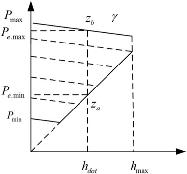
FIGURE 1. The diagram of heat-electricity relationship for combined heat power units.
The electrothermal characteristics can be expressed as follows:
where
After installing the energy storage system, the operation of the traditional cogeneration unit will be greatly changed. First of all, after adding the heat storage device, when the cogeneration unit outputs the same heat power, the electric output adjustment range increases (Yu et al., 2019). The addition of energy storage battery further increases the regulation range of electric output, which can effectively decouple the thermoelectric coupling characteristics and achieve the purpose of flexibly regulating the output of the thermoelectric unit.
2.3 Typical microgrid structure
2.3.1 Power storage system
The power storage system mainly includes battery, compressed air energy storage, flywheel energy storage, superconducting energy storage, super capacitor energy storage and other forms. This paper takes the most widely used battery as an example.
The state of charge (SOC) of the battery is a parameter reflecting the proportion of the remaining battery power to the total capacity of the battery. Generally, the relationship between SOC and the charging and discharging power and capacity of the battery is used to build a battery model.
The charging process is:
The discharge process is:
where
2.3.2 Heat storage system
Heat storage technology is divided into sensible heat storage and phase change heat storage. Generally, similar to energy storage battery, the thermal storage state of the thermal storage system and its charging and discharging power and thermal storage capacity are modeled as follows:
The heat storage process is:
The exothermic process is
where
2.4 Principle of optimal energy storage system configuration
The energy storage system is divided into electric energy storage system (battery) and thermal energy storage system. The configuration of the energy storage system includes power and capacity configuration. The power storage system includes battery, converter and other equipment, so the investment cost is settled in the form of power and capacity. The heat storage system includes heat storage tanks and heat transfer materials, so the investment cost is also settled in the form of power and capacity.
The configuration of the energy storage system affects the investment cost of the energy storage system, the operation cost of the entire microgrid, and the pollution control cost. The energy storage system with lower configuration can not meet the expected economy and stability of the system, can not effectively reduce the operating costs, and the content of pollutants emitted is high. The investment cost of energy storage system with higher configuration is high, and the overall maintenance cost is relatively high. Therefore, the optimal configuration of energy storage system can reach a balance point among investment cost, operation cost and pollution control cost, that is, the configuration of energy storage system with the minimum total cost.
2.5 Life model of energy storage battery
The life of the energy storage battery is affected by many factors, including the discharge depth, rate performance, charge and discharge cut-off voltage and ambient temperature of the battery. As mentioned above, the maximum power of the energy storage battery is taken as the rated value, so the influence of the battery’s magnification performance on its life is not considered for the time being. Since the capacity range of the energy storage battery has been set in the paper, the impact of the battery’s charge and discharge cut-off voltage on its life is not considered for the time being. The ambient temperature is regarded as room temperature, and its impact on battery life is not considered temporarily. After some simplifications, this paper only considers the influence of the discharge depth on the battery life, so we can use the rain flow counting method to predict the battery life.
The rain flow counting method, also known as the “tower top method,” was proposed by two British engineers Matsuiski and Endo. The rain flow counting method is mainly used in the engineering field, especially in the calculation of fatigue life.
The commonly used fitting methods include N-order function method, power function method and subsection fitting method. In this paper, the fourth order function in literature (Xiaojuan et al., 2013) is used to characterize the relationship between cycle life and discharge depth.
where Cyc is the maximum number i of cycles corresponding to the first cycle;
Since the energy storage system considered in this paper includes two aspects: power storage and heat storage, the SOC curve of the energy storage battery is significantly different after the heat storage system is installed in the heating period and non-heating period, so the method of calculating the life of the traditional rain-flow counting method is further improved. The heating period is 120 days from November to March of the next year; The non-heating period is from April to October, with a total of 245 days:
where
In this way, the life of the energy storage system can be estimated by constructing the charge-discharge curve of the battery in a typical day in the heating period and non-heating period.
2.6 Principle of energy storage system absorbing wind power
Due to the coupling relationship between the generating output and the heating output of the thermoelectric unit, the adjustable range of the generating power of the unit is limited by the heating output under a certain heating power (Bartnik et al., 2021).
In the independent microgrid, due to excessive wind power at night, it is impossible to connect to the grid. Therefore, during the winter heating period, the power generation output of thermoelectric units cannot be reduced due to heat supply constraints, resulting in more serious wind abandonment. After installing heat storage devices in the microgrid, the thermoelectric units supply heat load and also store heat to the heat storage device during the non-wind abandonment period. During the wind abandonment period, the output of the thermoelectric units can be reduced, while the insufficient heat supply is supplemented by the heat stored by the heat storage device, so as to accept more wind power and minimize the wind abandonment.
3 Optimal configuration model of energy storage system
According to the principle of the highest economic efficiency and maximum benefit in the microgrid, this paper aims at minimizing the total economic cost of the system, and establishes a planning system model including the investment cost of the energy storage system, the operation cost of the microgrid, and the pollution control cost, as shown in Figure 2.
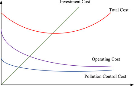
FIGURE 2. Each cost diagram of the system.
3.1 Objective function
In the optimization configuration of energy storage system, we take economy as the optimization objective, and propose the following objective function:
Where
The investment coefficient per unit capacity of battery is as follows:
Where
Generation cost can generally be expressed as a quadratic function of generation power. The power cost functions of conventional thermal power units and cogeneration units are:
Where:
It can be seen that Eqs 16, 17) are nonlinear, which brings difficulty to the solution of the model. To linearize the equations, the piecewise linearization technique is adopted, the detailed description of which in (Tuladhar et al., 2022).
3.1.1 System constraints
(1) Electrical power balance constraint
Where
(2) Heating power balance constraint
Where
(3) Wind power output constraint
Where
3.1.2 Unit constraints
(1) Unit output constraint:
Where
(2) Thermal output constraint of steam extraction unit:
Where
(3) Gross power ramp constraints for the unit:
Where
(4) Thermal Climbing Constraints for Steam Extraction Units:
Where
3.1.3 Energy storage system constraint
(1) Energy storage battery output constraints:
Where
(2) Thermal storage system output constraints:
Where
3.1.4 Self-sufficiency probability constraint
In the independent operation mode of the microgrid, it is particularly important to meet the load requirements and achieve system stability. Therefore, we introduce the concept of self-sufficiency probability. Configure the energy storage system by constraining the probability of meeting the load demand within the planning period, considering the load and wind output prediction errors.
For electrical loads:
For thermal loads:
Where
4 Solution method
The bacterial colony chemotaxis algorithm is an improvement of the bacterial chemotaxis algorithm (BC). By exchanging information with surrounding peers, bacteria can greatly save search time in the solution space, which improves speed and convergence while retaining the simplicity and robustness of the BC algorithm. This article adopts a bacterial population chemotaxis algorithm based on unit output and energy storage system power allocation strategy.
Each row of 4 bacteria represents the rated power and capacity of the power storage system, as well as the rated power and capacity of the heat storage system. In order to reasonably coordinate the power output within the system in the microgrid to meet the needs of the load. Ensure real-time power balance between power output and load demand at each time period, prevent overcharging and discharging of the energy storage system, and achieve optimized scheduling of distributed power sources in the microgrid. In the actual planning process, it is often necessary to select a reasonable power allocation strategy, which can effectively improve the efficiency of generating feasible solutions and thereby improve algorithm performance.
The planning cycle of energy storage systems is generally divided into heating period and non heating period. The non heating period generally refers to April to October, when the cogeneration unit and heat storage system stop operating. The heating period generally refers to November to March of the following year, when the cogeneration unit and heat storage system are put into operation.
During non heating periods, wind power is prioritized in microgrids, and excess wind power is stored through energy storage batteries. If wind power is insufficient, conventional units are used to supplement output demand.
During the heating period, due to the fact that the loss cost of charging and discharging heat in the heat storage system is much lower than that of charging and discharging batteries, priority is given to utilizing the heat storage system to absorb wind power. The specific operation strategy is as follows:
Firstly, determine whether the period is in the wind abandonment stage, based on whether the wind power output meets the electricity load demand. If during the wind abandonment stage, the heat storage system releases heat, the cogeneration unit prioritizes supplementing the heat load demand, and the electricity load prioritizes consuming the output of wind power and cogeneration units. Excess electricity is stored through energy storage batteries. If in the non wind abandonment stage, the thermal power unit not only meets the thermal load but also stores heat for the heat storage system, and then judges the charging and discharging needs of the energy storage system based on the power load. If there is insufficient power, it will be supplemented by conventional thermal power units. The specific steps are shown in Figure 3.
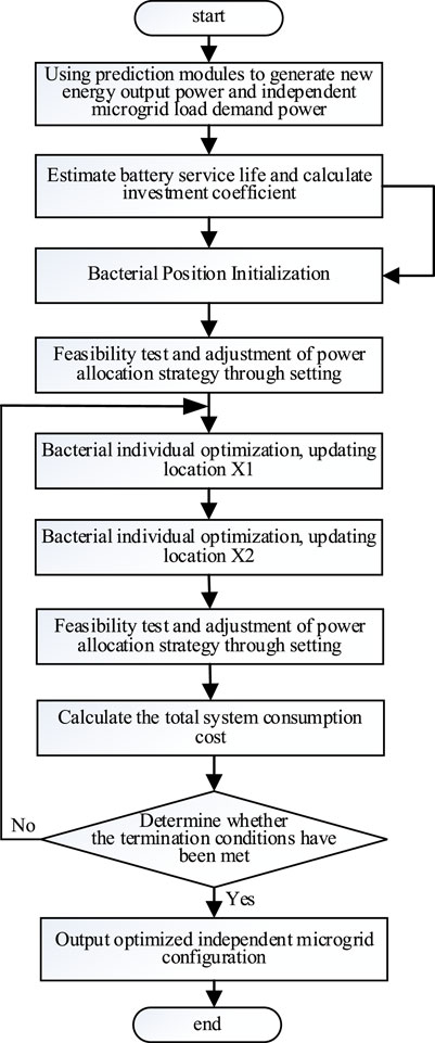
FIGURE 3. The calculation process of bacterial colony chemotaxis algorithm.
5 Case studies
5.1 Case description
In this paper, a 6-unit system is used for simulation, with a planning period of 1 year. The system consists of 3 conventional thermal power units, 2 extraction thermoelectric units, and 1 wind turbine. The system load is divided into heating and non-heating periods, and the wind power is predicted by selecting historical data from an island. The island load is mainly residential load. The coal consumption characteristic parameters and electric heating output operation parameters are shown in (Jiaming et al., 2016). The self-sufficiency probability requirement is 90%. The self-sufficiency probability prediction error normal distribution
The number of bacteria is 50, the maximum number of iterations is 100, the initial accuracy is 2, the final accuracy is 0.01, the accuracy update constant is 1.25, and each bacteria moves at a speed of 1.
The configuration is tested on a personal computer with Intel(R) Core (TM) i7-8565U CPU and 8.00 GB RAM using MATLAB R2020b.
In order to compare and analyze the economic benefits of energy storage system configuration on the system, three different scenarios are set up:
Scenario A: There is no energy storage device in the system;
Scenario B: Adding a randomly configured energy storage system to the system;
Scenario C: Configure an optimized energy storage system in the system.
5.2 Simulation results
5.2.1 Analysis of optimization results
Select a typical heating and non-heating day, and the SOC curve of the energy storage battery in the ideal state (that is, not limited by capacity, but only related to load demand) is shown in Figures 4, 5. As can be seen from the figure, during the non-heating period, there are 4.5 cycles with discharge depths of 0.6, 0.6, 0.2, and 0.2, respectively. The heating period is 2.5 cycles, and the discharge depth is 0.4 and 0.4, respectively. According to calculation, the annual life loss rate is about 0.45. During the heating period, as wind power is mainly dissipated through the heat storage system, the SOC of the energy storage battery has a small change. It can be estimated that the service life of the energy storage battery is about 2.2 a, and then the annual investment coefficient per unit capacity of the energy storage battery is 66 $/(kW·h)·a.
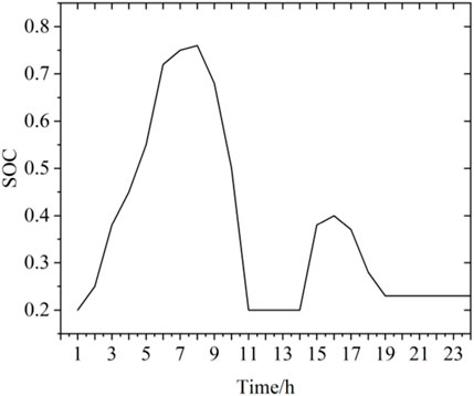
FIGURE 4. A typical SOC curve during the non-heating period.
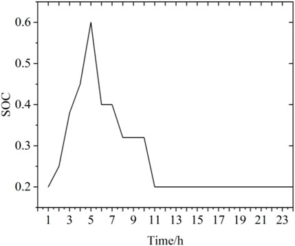
FIGURE 5. Typical SOC curve during the heating period.
The total cost of Scenario A is 171.1902 million $, including 171.118 million $ of operation cost and 10,200 $ of pollution control cost. The probability of self-sufficiency in electrical load is 65%, and the probability of self-sufficiency in thermal load is 87%, which does not meet the requirements. During non-heating periods, thermal power unit 1 operates all the time, and during periods of insufficient output, it is supplemented by thermal power units 2 and 3. During the heating period, the operation of thermoelectric units gives priority to meeting the thermal load. Due to the “heat to power” mode of air extraction units, when wind energy resources are sufficient in winter, a large amount of wind energy will be discarded.
Scenario B randomly selects the configurations of 3 MW and 5 MW·h energy storage batteries and 1 MW and 6 MW·h heat storage systems, with a total cost of 79.364 million $, of which the investment cost of the energy storage system is 1.08 million $, the operation cost of the microgrid and the pollution control cost are 78.346 million $ and 9,700 $, respectively. Compared to Scenario A, the total cost decreased by 53% year-on-year. The main reason for the decrease in total cost is that after configuring the energy storage system, the energy storage battery can reduce peak load and valley load, optimize output scheduling, reduce wind power losses, and the heat storage system can increase the utilization rate of wind power during the heating period, avoiding the generation of abandoned wind, resulting in a decrease in total cost. Under this scheme, the probability of self-sufficiency of electrical load is 97%, and the probability of self-sufficiency of thermal load is 99%, which meets the self-sufficiency probability set by the system.
Scenario C uses the energy storage system optimization configuration method proposed in the article to seek the optimal configuration, and obtains the optimal configuration of 2.6 MW, 9.1 MW·h energy storage batteries, and 2.2 MW, 10 MW·h heat storage systems, which is the optimal configuration sought. Under this configuration, the total cost is 77.751 million $, compared to Scenario A, the total cost decreased by 54% year-on-year, and compared to Scenario B, the total cost decreased by 2% year-on-year. Among them, the investment cost of energy storage system is 1548000 $, the operation cost of microgrid and the pollution control cost are 76.193 million $ and 9,300 $ respectively. The probability of self-sufficiency of both electrical and thermal loads in this configuration is 99%. Compared to Scenario B, the reason for the total cost reduction is that the system is configured with an optimized energy storage system, which can more effectively optimize system output and reduce wind abandonment. The specific comparison results are shown in Table 1.
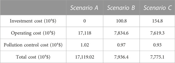
TABLE 1. Cost in different scenes.
As can be seen from Figure 6A, in the wind abandonment phase of the microgrid, the energy storage batteries are charged. In the non-wind abandonment phase, after using the wind power, priority is given to replenishing the output through the energy storage batteries, which can effectively reduce peak load and valley load, reducing energy consumption.
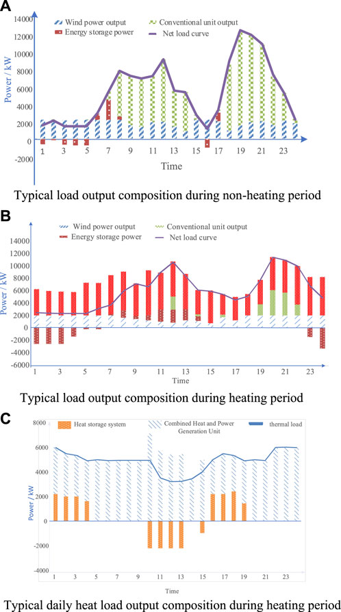
FIGURE 6. Composition of load output on a typical day during the heating and non-heating periods. (A) Typical load output composition during non-heating period. (B) Typical load output composition during heating period. (C) Typical daily heat load output composition during heating period.
Figures 6B, C show the electricity and heat output during the heating period. During the wind abandonment stage, the heat storage system releases heat energy and the cogeneration unit jointly meet the heat load. At this time, the cogeneration unit has a small output, and wind energy can be preferentially utilized to reduce wind abandonment. In this case, there is sometimes still a large amount of remaining electrical energy, and at this time, energy storage batteries can be used to store electrical energy. In the non-wind abandonment stage, the thermoelectric unit stores heat for the heat storage system while meeting the thermal load, and then judges the charging and discharging requirements of the power storage system based on the electrical load. It can be seen that the introduction of a multi-purpose storage system into the microgrid has increased the flexibility and system benefits of the microgrid, reducing the generation of wind abandonment.
The operating cost during the non-heating period only considers the power and capacity of the energy storage battery. As shown in Figure 7, selecting a series of data with a step size of 1 MW, it can be seen that as the system configuration increases, the system operating costs gradually decrease, while the investment costs increase, and the pollution control costs decrease.
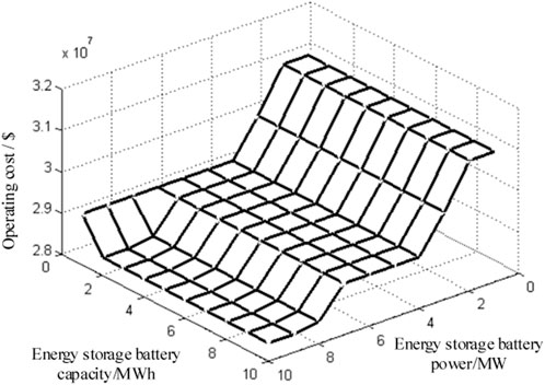
FIGURE 7. Relationship between operation cost and energy storage system sizing during the non-heating period.
During the heating period, the overall configuration of energy storage batteries and heat storage systems is considered. As the configuration increases, the investment cost of the energy storage system increases, and the operating cost and pollution control cost of the microgrid also decrease.
5.2.2 Analysis of wind power absorption effect
Figure 8 shows the exhaust air volume under different scenarios on a typical day during a heating period. It can be seen that the total exhaust air volume under scenario 1 reaches 39.11 MW. The reason is that during the heating period, the production mode of the cogeneration unit “determining power based on heat” causes the forced power output of the system to be too high due to heating. After adding energy storage, the exhaust air volume for Scenario 2 and Scenario 3 is 8.19 MW and 7.84 MW, respectively, greatly reducing the exhaust air volume. It can be seen that the existence of energy storage systems has significantly improved the acceptance of wind power, which has played a positive role in the overall economy of the system.
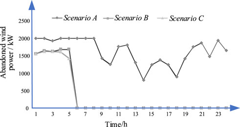
FIGURE 8. Comparison of typical drought scenarios during the heating period.
5.2.3 Comparative analysis with traditional optimal allocation methods
During the comparative analysis process, the following scenarios are set up.
Scenario D: Adding an energy storage system with traditional optimization configuration methods to the system.
The main difference between the traditional optimal configuration method for energy storage systems and the configuration method in this paper is that the traditional method does not consider the difference between the SOC curve heating period and the non-heating period when estimating the life of the energy storage system.
When estimating the life of energy storage batteries using traditional configuration methods, the SOC curve of a typical day is generally selected. Here, selecting a typical non-heating period SOC curve, as shown in Figure 4, it can be obtained that the discharge depths for 4.5 cycles are 0.6, 0.6, 0.2, and 0.2, respectively. After calculation, the annual loss rate is 0.55, and the estimated life of the power storage system is about 1.8 years. The main reason for calculating this result is that the difference between the SOC curve during the heating period and the non-heating period is not considered. During the heating period, the SOC curve of the energy storage battery changes slightly due to the dissipation of waste air mainly through the charging and discharging effects of the heat storage system. Therefore, using traditional methods to estimate the life of energy storage batteries has generated certain errors, resulting in inaccurate investment cost calculations.
5.2.4 Sensitivity analysis of energy storage system investment
The annual unit power investment coefficient is larger than the annual unit capacity investment of the energy storage system. This section mainly analyzes the impact of the annual unit power investment coefficient of the energy storage system on the optimal configuration and total cost of the energy storage system. Taking a series of data with other cost factors unchanged, the resulting results are shown in Figure 9. It can be seen that when it is small, due to the lower investment unit cost, the optimal configuration power of the power storage system is larger, which also brings benefits to the system. As the investment increases, the unit cost of investment increases, and the optimal allocation of power increases, while the system benefits also decrease due to the reduced configuration of the energy storage system. Other cost factors have similar effects.
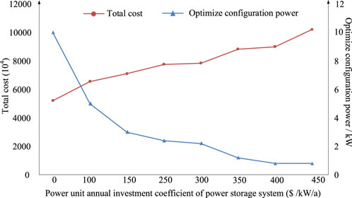
FIGURE 9. The optimal size of ESS rated power and total cost under different.
6 Conclusion
This paper proposes a model for optimal configuration of energy storage systems in microgrids, and the following conclusions are obtained.
(1) The configuration of energy storage systems in a microgrid can affect the investment cost of energy storage systems, as well as the operating and pollution control costs of the entire microgrid. As a constraint in system operation, it affects the selection of power allocation strategies for the entire microgrid. Therefore, selecting a more reasonable configuration of the energy storage system can improve the utilization rate of new energy and increase system revenue.
(2) The reasonable configuration of the energy storage system can, to a certain extent, avoid wind abandonment caused by the forced power output of the cogeneration unit in the “heat to power” mode during the winter heating period, thereby improving the overall economy and low-carbon performance of the independent microgrid.
Further research should consider the configuration and coupling relationship of electricity, gas, and heat storage in the integrated energy microgrid, as well as the planning and configuration of composite energy storage and energy conversion devices such as P2G and liquid hydrogen SMES in the microgrid. In existing models, in order to more accurately estimate the life of the energy storage system, it is possible to further consider a modified model that predicts the life changing with the actual situation. At the same time, the main research object of this article is independent microgrids, which can continue to be studied.
Data availability statement
The original contributions presented in the study are included in the article/Supplementary material, further inquiries can be directed to the corresponding author.
Author contributions
JC: Writing–original draft, Writing–review and editing.
Funding
The author(s) declare that no financial support was received for the research, authorship, and/or publication of this article.
Conflict of interest
The authors declare that the research was conducted in the absence of any commercial or financial relationships that could be construed as a potential conflict of interest.
Publisher’s note
All claims expressed in this article are solely those of the authors and do not necessarily represent those of their affiliated organizations, or those of the publisher, the editors and the reviewers. Any product that may be evaluated in this article, or claim that may be made by its manufacturer, is not guaranteed or endorsed by the publisher.
References
Bahramirad, S., Reder, W., and Khodaei, A. (2012). Reliability-Constrained optimal sizing of energy storage system in a microgrid. IEEE Trans. Smart Grid 3 (4), 2056–2062. doi:10.1109/TSG.2012.2217991
Bartnik, R., Buryn, Z., and Hnydiuk-Stefan, A. (2021). Thermodynamic and economic analysis of effect of heat accumulator volume on the specific cost of heat production in the gas-steam CHP plant. Energy 230, 120828. doi:10.1016/j.energy.2021.120828
Chen, Y., Lu, H., Li, J., Huang, G., and He, L. (2016). Regional planning of new-energy systems within multi-period and multi-option contexts: a case study of Fengtai, Beijing, China. Renew. Sustain. Energy Rev. 65, 356–372. doi:10.1016/j.rser.2016.07.017
Fengbing, L., Kaigui, X., Xuesong, Z., et al. (2014). Optimization of coordinated control parameters for hybrid energy storage system based on life quantization. Automation Electr. Power Syst. 38 (1), 1–5. doi:10.7500/AEPS20130503006
Heijde, V., Vandermeulen, A., Salenbien, , and Helsen, (2019). Integrated optimal design and control of fourth generation district heating networks with thermal energy storage. Energies 12 (14), 2766. doi:10.3390/en12142766
Hengyu, H., Minglei, B., Yi, D., et al. (2022). Exploring the integrated flexible region of distributed multi-energy systems with process. industry” Appl. Energy 311, 118590. doi:10.1016/j.apenergy.2022.118590
Jiaming, L., Xueyang, Z., Xiaomeng, A., Jinyu1, W., Shumin, S., and Guanglei, L. (2016). Optimal design of capacity of distributed generation in island standalone microgrid. Trans. China Electrotech. Soc. 31 (10), 178–184. doi:10.19595/j.cnki.1000-6753.tces.2016.10.021
Junyi, Z., Sheng, W., Lei, G., Jiang, Y., Kang, Z., and Jones, C. N. (2022). Data-driven distributionally robust joint chance-constrained energy management for multi-energy microgrid. Appl. Energy 326, 119939. doi:10.1016/j.apenergy.2022.119939
Kousksou, T., Bruel, P., Jamil, A., El Rhafiki, T., and Zeraouli, Y. (2014). Energy storage: applications and challenges. Sol. Energy Mater. Sol. Cells 120, 59–80. doi:10.1016/j.solmat.2013.08.015
Liu, W., Wang, D., Liu, B., Yu, X., Jia, H., Wang, W., et al. (2020). Design and evaluation of micro energy network considering P2G-based storage system using two-stage stochastic programming. IET Renew. Power Gener. 14 (17), 3346–3355. doi:10.1049/iet-rpg.2020.0161
longyun, L., Bo, H., and Kaigui, X. (2016). Capacity optimization of hybrid energy storage systems inisolated microgrids based on discrete fourier transform. Automation Electr. Power Syst. 40 (12), 108–116. doi:10.7500/AEPS20150625011
Marc, B., Hamidreza, Z., Anthony, S., and Rosehart, W. (2010). Energy storage for mitigating the variability of renewable electricity sources:an updated review. Energy Sustain. Dev. 14 (4), 302–314. doi:10.1016/j.esd.2010.09.007
Minglei, B., Hengyu, H., Yi, D., Sun, X., Zheng, C., and Gao, X. (2023). An efficient framework for exploiting operational flexibility of load energy hubs in risk management of integrated electricity-gas systems. Appl. Energy 338, 120765. doi:10.1016/j.apenergy.2023.120765
Pratama, Y. W., Purwanto, W. W., Tezuka, T., McLellan, B. C., Hartono, D., Hidayatno, A., et al. (2017). Multi-objective optimization of a multiregional electricity system in an archipelagic state: the role of renewable energy in energy system sustainability. Renew. Sustain. Energy Rev. 77, 423–439. doi:10.1016/j.rser.2017.04.021
Rohit, A. K., and Rangnekar, S. (2017). An overview of energy storage and its importance in Indian renewable energy sector: part II – energy storage applications, benefits and market potential. J. Energy Storage 13, 447–456. doi:10.1016/j.est.2017.07.012
Roy, P. K., Paul, C., and Sultana, S. (2014). Oppositional teaching learning based optimization approach for combined heat and power dispatch. Int. J. Electr. Power Energy Syst. 57, 392–403. doi:10.1016/j.ijepes.2013.12.006
Sadeghian, O., Moradzadeh, A., Mohammadi-Ivatloo, B., Abapour, M., and Garcia Marquez, F. P. (2020). Generation units maintenance in combined heat and power integrated systems using the mixed integer quadratic programming approach. Energies 13 (11), 2840. doi:10.3390/en13112840
Sezgin, S. (2018). The Third Industrial Revolution: how lateral power is transforming energy, the economy, and the world. Turk. J. Bus. Ethics 11 (1). doi:10.12711/tjbe.2018.11.1.0005R
Sheng, W., Hongxun, H., Yi, D., Ye, C., and Zheng, M. (2023). Operational reliability evaluation of urban multi-energy systems with equivalent energy storage. IEEE Trans. Industry Appl. 59, 2186–2201. doi:10.1109/tia.2022.3232099
Shiming, T., Wenpeng, L., Dongxia, Z., et al. (2010). Technical forms and key technologies on energy internet. Proc. CSEE 35 (14), 3482–3494. doi:10.13334/j.0258-8013.pcsee.2015.14.002
Teng, Y., Sun, P., Leng, O., Chen, Z., and Zhou, G. (2019). Optimal operation strategy for combined heat and power system based on solid electric thermal storage boiler and thermal inertia. IEEE Access 7, 180761–180770. doi:10.1109/ACCESS.2019.2958877
Tuladhar, S. R., Singh, J. G., and Ongsakul, W. (2022). Multi objective optimal scheduling of integrated electricity-gas SystemBased on piecewise linearization and improved second order cone relaxation. Trans. China Electrotech. Soc. 37 (11), 2800–2812. doi:10.19595/j.cnki.1000-6753.tces.210463
Wang, S., Zhai, J., Hui, H., Ding, Y., and Song, Y. (2023). Operational reliability of integrated energy systems considering gas flow dynamics and demand-side flexibilities. IEEE Trans. Industrial Inf., 1–13. doi:10.1109/TII.2023.3275712
Xiao, B., Zhang, Y., Han, J., Liu, D., Wang, M., and Yan, G. (2019). A multi-energy complementary coordinated dispatch method for integrated system of wind-photovoltaic-hydro-thermal-energy storage. Int. Trans. Electr. Energy Syst. 29 (7). doi:10.1002/2050-7038.12005
Xiao, C., Junyi, Z., Yuning, J., Ni, C., Wang, S., and Nimmegeers, P. (2023). Decentralized coordination between active distribution network and multi-microgrids through a fast decentralized adjustable robust operation framework. Sustain. Energy Grids Netw. 34, 101068. doi:10.1016/j.segan.2023.101068
Xiaojuan, H., Cheng, C., Tianming, J., and Huimeng, M. (2013). Capacity optimal modeling of hybrid energy storage systems considering battery life. Proc. CSEE 33 (34), 91–97. doi:10.13334/j.0258-8013.pcsee.2013.34.015
Xie, Q., Wang, Y., Kim, Y., Pedram, M., and Naehyuck Chang, (2013). Charge allocation in hybrid electrical energy storage systems. IEEE Trans. Comput.-Aided Des. Integr. Circuits Syst. 32 (7), 1003–1016. doi:10.1109/TCAD.2013.2250583
Yu, H., Zhang, K., Liu, Y., Dai, J., and Sun, Z. (2019). “Micro-grid scheduling of electric boiler and CHP with thermal energy storage based on wind power accommodating,” in Proceedings of the 2019 IEEE 10th International Symposium on Power Electronics for Distributed Generation Systems (PEDG), Xi’an, China, June. 2019, 336–340. doi:10.1109/PEDG.2019.8807672
Yuming, S., Bo, H., Kaigui, X., et al. (2014). Optimal economic operation of isolated microgrid considering battery life loss. Power Syst. Technol. 38 (9), 2371–2378. doi:10.13335/j.1000-3673.pst.2014.09.009
Keywords: integrated energy microgrid, multi-energy storage system, optimal sizing methods, battery life, heat storage system
Citation: Chen J (2023) Optimize configuration of multi-energy storage system in a standalone microgrid. Front. Energy Res. 11:1283859. doi: 10.3389/fenrg.2023.1283859
Received: 27 August 2023; Accepted: 16 October 2023;
Published: 26 October 2023.
Edited by:
Minglei Bao, Zhejiang University, ChinaCopyright © 2023 Chen. This is an open-access article distributed under the terms of the Creative Commons Attribution License (CC BY). The use, distribution or reproduction in other forums is permitted, provided the original author(s) and the copyright owner(s) are credited and that the original publication in this journal is cited, in accordance with accepted academic practice. No use, distribution or reproduction is permitted which does not comply with these terms.
*Correspondence: Jun Chen, MjAyMzEwMDA3NDczQG5qdGVjaC5lZHUuY24=