 Jinglin Han1,2
 Xichun Feng
94% of researchers rate our articles as excellent or good
Learn more about the work of our research integrity team to safeguard the quality of each article we publish.
Find out more
ORIGINAL RESEARCH article
Front. Energy Res. , 18 September 2023
Sec. Sustainable Energy Systems
Volume 11 - 2023 | https://doi.org/10.3389/fenrg.2023.1278648
This article is part of the Research Topic Smart Energy System for Carbon Reduction and Energy Saving: Planning, Operation and Equipments View all 42 articles
The virtual synchronous generator (VSG) control strategy is proposed to mitigate the low inertia problem in the power system brought about by the high percentage of distributed generation connected to the grid and the application of power electronic devices. In order to maximize the effectiveness of the advantages of the flexible and adjustable parameters of VSG control, an adaptive VSG control strategy considering SOC constraint of the energy storage unit is proposed in this paper. Considering the significant loss of service life by operating the energy storage unit at its limit state, based on the rate and degree of change in system frequency, the adaptive control strategy realizes the online adaptive adjustment of the inertia factor and damping factor under different perturbation conditions by adaptively adjusting the control parameters when the system frequency oscillates. Finally, the effects of this adaptive VSG control method and conventional VSG control method are compared by simulation in PLECS. Hardware-in-the-loop (HIL) experimental platforms and semi-physical simulation experiments are constructed on RTBOX, and the feasibility and validity of this adaptive VSG control strategy are verified.
The “carbon neutral” and “carbon peak” targets proposed by China in 2020 have led to the rapid development of distributed generation devices represented by photovoltaic power generation and wind power generation, which has also changed China’s power system dramatically from a traditional grid with synchronous generators to a new “double-high” grid which is characterized by containing a high proportion of distributed generation and power electronics (Jiang et al., 2021). The power electronic converter-based “double-high” power system is different from the synchronous generator: there is no rotational inertia to stabilize the system frequency, which will lead to faster frequency change and bigger fluctuation when the system frequency fluctuates, and it is easier to trigger the system protection device, which has a serious impact on the dynamic response. In addition, grid frequency fluctuations can cause huge economic damage to users with high power quality requirements. This is of great significance to the grid’s consumption of distributed generation and the realization of smooth grid connection, which will reduce the difficulty of scheduling and control of large-scale distributed energy grid connection by enabling grid-connected inverters for distributed generation to have inertial support capacity and damping characteristics similar to synchronous generators (Zheng et al., 2015). As a result, some researchers proposed the virtual synchronous generator (VSG) control method (Beck and Hesse, 2007; Lv et al., 2012; Shi et al., 2016), which allow the grid-connected inverter to provide inertial support by having rotational inertia and damping factor similar to those with the synchronous generator.
Based on the idea of inverters simulating synchronous generators, the EU set up the VSYNC project in 2007 to implement this approach in order to solve the system stability problems associated with grid-connected distributed power sources. Two solutions have been proposed under the auspices of the VSYNC project, namely, the virtual synchronous machine (VISMA) concept by Prof. Hans–Peternal Beck of the Technical University of Clausthal, Germany, and the concept of the VSG control method was proposed by Prof. J. Driesen of KU Leuven, Belgium, and Prof. K. Visscher of the Netherlands Energy Research Centre (Visscher and De Haan, 2008; Zhang et al., 2017a). Since then, the “virtual inertial frequency control” method was proposed by Professor M. Reza Iravani’s team at the University of Toronto, and the concept of the “Synchronverter” was developed by Professor Qingchang Zhong at the University of Liverpool (Zhong, 2010; Sakimoto et al., 2011), which laid the foundation for research on VSG control. Researchers have continued to improve on this basis: the differential link was introduced into the droop controller of the VSG in the literature (Beck and Hesse, 2007) to eliminate the lag effect of the system controller due to calculation and to reduce the operating voltage difference and frequency deviation of the inverters operating in parallel. Based on multi-energy complementary microgrids in the literature (Lv et al., 2012), a new VSG control algorithm is proposed to improve the power quality of the system. In addition, many papers have improved the VSG control algorithm in different ways from different aspects and verified its advantages over the traditional control algorithm. The research on the VSG control strategy is relatively mature, but it is mostly limited to controlling the inverter output constant moment of inertia to simulate the synchronous generator and fails to effectively exploit the flexible controllability of the virtual inertia.
The VSG control combining distributed generation units and energy storage units has become a contemporary research hotspot to take advantage of the flexibility and controllability of the VSG control method. The research is most prominent in the field of distributed power generation represented by wind energy, photovoltaic, and energy storage, which enables to make distributed power sources such as wind and storage have the function of primary frequency regulation and voltage regulation while being stable and connected to the grid. For DIFG with the VSG control, Zhang et al. (2017b) provided system inertia by analogizing the wind turbine converter DC side to rotor motion. Wang et al. (2011) introduced a VSG-controlled energy storage system on the AC output side of the system with inertia and damping characteristics of the wind power generation system. A VSG control strategy without a phase-locked loop is proposed in Wang et al. (2015), and the effect of wind energy fluctuations on the wind turbine momentum variation is analyzed. The energy storage unit was connected to the DC side of the wind power generation in Zeng et al. (2015), and the study proposed that the rotor kinetic energy of the wind turbine is limited and only suitable for short-time inertia and damping support; adding the energy storage unit can improve the inertial support capacity and damping of the wind turbine, which can provide a more durable regulation capability for the system, and also integrate the relationship between energy storage capacity and inertia damping to establish the optimal configuration scheme of energy storage. The effect of reactive power on the VSG control operation parameters was studied in Yuan et al. (2017), where the parameter selection boundary considering the system reactive power was proposed, and the mechanism of the action of inertia and damping was illustrated by analyzing the effect of different inertia levels and damping factors on the characteristics of VSG operation. The influence of the energy storage SOC on the selection of VSG operating parameters was analyzed in Xin et al. (2015), and the upper and lower boundaries for the selection of VSG operating parameters were obtained to ensure safe and stable operation of the system.
An inertia calculation method for energy storage systems is presented in Hu et al. (2018a) to evaluate the equivalent inertia provided by using VSG control methods. It is stated in Deng et al. (2018) that the use of VSG control allows the energy storage device to participate in the primary frequency regulation process of the system, but when the frequency deviation is very large, the sag control leads to a decrease in the frequency stability of the system. In Hu et al. (2018b), by using the SOC of the energy storage unit as a constraint, the energy storage device is made to provide inertia support for the system with the service life taken into account, but removing the SOC hastily because the energy storage device is in the limiting operation state will lead to system instability. The transient stability of power systems containing energy storage devices was analyzed in Chen et al. (2018), and a linear feedback inertia measurement method was proposed to discuss the effects of control parameters, energy storage capacity, and communication delay on the system inertia constant but without providing a solution. In Hammad et al. (2017), adaptive control of energy storage devices is used to achieve flexible changes in system inertia, which can improve the penetration level of distributed generation devices and the integration of multiple microgrids, but the impact of the energy storage system’s own characteristics on the virtual inertia is ignored. The effect of the load-side LC filter on the DC voltage is mostly ignored in the aforementioned studies, which consider the load side as A load with constant power. Zhang et al. (2019) compared photovoltaic and wind power generation in terms of energy storage, pointing out that unlike the rotating mechanical structure of wind turbines, stationary photovoltaic elements have no energy storage capacity, while energy storage units and capacitors as energy storage elements can only call on stationary energy. The power angle characteristic and rotor oscillation curves in synchronous generators are considered in Zhu et al. (2021), and the mechanism of the rotational inertia effect on the frequency stability of the microgrid is analyzed. An adaptive rotational inertia VSG control strategy was proposed in Li et al. (2020), which offers some superiority over droop control in terms of frequency regulation. Zhu et al. (2020) investigated the adaptive rotational inertia of VSGs, which adjusts the magnitude of rotational inertia according to the amount of deviation and the rate of change of frequency due to load changes. However, this study was conducted on a single subject. The VSG control for PV systems without energy storage was designed in Zheng et al. (2017) so that PV systems without storage can also simulate synchronous generator characteristics. Energy storage and PV systems were combined in He (2015) to make the PV system inertial and damped by VSG control. The VSG control scheme for PV storage systems from an energy management point-of-view was improved in Li et al. (2017) to improve the self-coordinated distribution of power between multiple distributed sources. To address the power coupling problem in the control of PV systems in practice, Arco et al. (2015) and Qu et al. (2018) proposed a VSG control strategy with increased virtual impedance to solve the coupling problem.
In summary, this paper proposes an adaptive VSG control method, which adjusts the control according to the SOC of the energy storage unit and the frequency change of the system, from the considerations of prolonging the service life of the energy storage unit and improving the dynamic response capability of the VSG control, with the main contributions.
(1) An adaptive VSG method is proposed by dividing the SOC state of the energy storage unit; when the SOC is in the limit state, the size of the virtual inertia can be adjusted autonomously according to its SOC so as to avoid deep charging and discharging loss of the energy storage unit.
(2) When the SOC is in the safe operation interval, the controller can automatically adjust the inertia support capacity provided by the energy storage unit, according to the change in the system frequency, accelerate the system frequency recovery, realize the adaptive control, and enhance the stability of the system operation. Compared with the conventional VSG control method, this method combines the different states of SOC and the system frequency changes to improve the frequency characteristics of the system under the premise of ensuring the safe and stable operation of the system.
(3) The simulation and semi-physical models of the three-terminal optical storage microgrid system are built in PLECS, and the validity of the control method and the reference significance for engineering practice are proved by conducting hardware-in-the-loop (HIL) experiments in RTBox.
The rest of the paper is structured as follows: Section 2 introduces the VSG control principle, the microgrid structure with PV and energy storage, and the power system inertia assessment method considering distributed power connection. Section 3 classifies the SOC states and proposes an adaptive VSG control method considering the energy storage SOC constraints. Section 4 verifies the effectiveness of the method through corresponding simulations and HIL experiments. Finally, conclusions are drawn in Section 5.
This paper takes a four-terminal AC PV-storage microgrid as the research model, which consists of four parts, namely, photovoltaic power generator, energy storage unit, synchronous generator G1, and load. The four-terminal AC PV-storage microgrid system topology is shown in Figure 1, where the AC-side grid-connected inverter of the PV storage unit adopts the VSG control strategy, the PV generation unit is a distributed generation unit with a constant power control mode, and the power fluctuations due to load fluctuations are smoothed by the energy storage device to maintain the system balance. Generator G1 works in a constant power model to satisfy the basic power requirements of the loads; the load side is a constant power load.
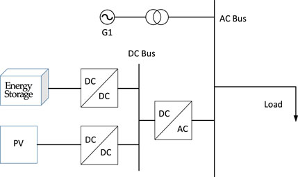
FIGURE 1. Topological diagram of the optical storage microgrid.
Figure 2 shows the system structure of VSG. Vdc represents the equivalent DC voltage source of the PV and energy storage units after they are converged to the DC bus through their DC/DC converters; Sa1,Sb1,Sc1,Sa2,Sb2,Sc2 is the control signal of the inverter switching tube; eabc is the root mean square value of the AC voltage output from the three-phase bridge arm of the inverter; Pref is the active power reference; Qref is the reactive power reference value; Vabc is the voltage at the output of the inverter; Lf is the filter inductor of the LC filter; Cf is the filter capacitor of the LC filter; and Zload is the equivalent impedance of the load.
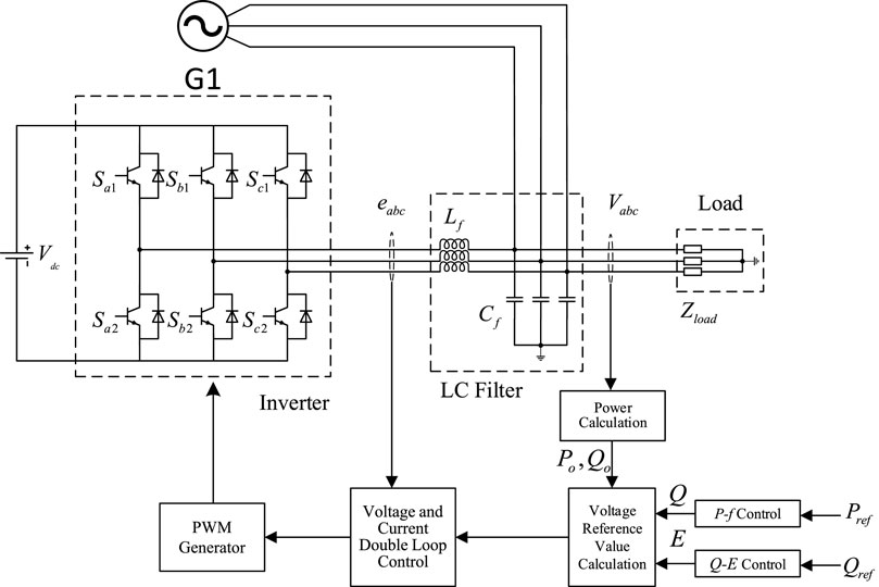
FIGURE 2. VSG system structure diagram.
The DC/AC inverter adopts the VSG control strategy and introduces a virtual inertia link in the d-axis control loop so that the output characteristics of the inverter are similar to those of the synchronous generator, with inertia regulation and primary frequency regulation. Similarly, the primary voltage regulation function of the inverter is realized by simulating the electromagnetic characteristics in the q-axis control loop. The control equations of both are as follows:
where Pin is the synchronous generator shaft power; Pout is the generated power; J is the system inertia coefficient; D is the system damping coefficient; ωm is the rotor angular velocity; and ωg is the grid angular velocity.
The swing equation of the synchronous generator is shown in Eq. 1.
The relationship between the sway equation and droop control can be obtained by combining the two as follows:
where P0 is the system reference power, Kp is the droop factor, ωm is the rotor angular velocity, ω0 is the reference angular velocity, Pout is the generated power, J is the coefficient of rotary inertia, D is the system damping factor, and ωg is the grid angular velocity.
Comparing the droop control equation and the synchronous generator sway equation, it can be seen that the synchronous generator sway equation is equivalent to the droop control equation when inertia and damping (i.e.) are not considered, so the droop control and VSG control relationship can be obtained as follows:
where Pin and Pout are the synchronous generator shaft power and power generated, respectively, Kp is the droop factor, ωm is the rotor angular velocity, ωg is the grid angular velocity, J is the coefficient of rotary inertia, and D is the system damping factor.
The VSG control method of the DC/AC inverter is shown in Figure 3. According to the rotor motion equation, the VSG control is introduced into the control system of the DC/AC inverter so that the inverter has a similar phase and amplitude of the potential inside the synchronous generator, where the expression of the rotor equation of motion is as follows:
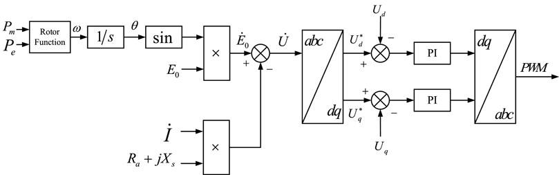
FIGURE 3. VSG control block diagram.
where P0 is the system reference power; Pout is the generated power; J is the system inertia coefficient; D is the system damping coefficient; ωVSG is the rotor angular velocity of VSG; ωm is the rotor angular velocity; ωg is the grid angular frequency; ω0 is the reference angular velocity; and Kp is the droop coefficient.
The virtual synchronous control strategy mainly consists of three parts, namely, the virtual inertia controller, active-frequency controller, and reactive-voltage controller, all of which use the droop controller and output power value Pm and voltage value E0, respectively, which are input to the virtual inertia controller. In the virtual inertia controller, the power value Pm and the real active power Pe are transformed by the rotor equation to obtain the rotor angular velocity ω of the VSG control method, and the voltage value E0 is input to the rotor converter through vector synthesis and virtual impedance, which generates a three-phase PWM modulated signal for controlling the DC/AC inverter after dq transformation and PI control. Similar to the wind turbine, the PV storage unit will respond to changes in system frequency by introducing a new variable in the reference power that is related to the system frequency and adjusting its own output power to suppress frequency fluctuations.
For the new “double-high” power system with a high percentage of renewable energy and power electronics, the distributed generation and power electronics need to provide different inertia support for different oscillation frequencies to improve the dynamic response of the system, so the equivalent rotational inertia of the system needs to be evaluated. When different proportions of distributed generation are connected to the grid by inverters with the VSG control, the equivalent total inertia Hz of the system can be expressed as follows:
where n is the number of synchronous machines in the system; Js,k and Pn,k are the rotational inertia and the number of pole pairs of synchronous machines, respectively; Sk and Ek are the rated capacity of synchronous machines and kinetic energy, respectively,
The power constraint and lifetime issues of energy storage systems in practical engineering applications are ignored in the current VSG control research, regardless of whether the control objective is to maintain constant inertia output or to consider the energy storage unit output power. The lifetime of the energy storage device can be significantly shortened by deep charging and discharging at the operating limit state.
In response to the aforementioned deficiencies in the VSG control method, an adaptive VSG control method that adaptively adjusts control parameters depending on the speed and amplitude of the system frequency change is proposed based on the consideration of the energy storage SOC constraint. On one hand, the strategy takes into account the amplitude and speed of the system frequency change, and can flexibly provide inertial support to maintain the system frequency stability according to the actual change situation. On the other hand, it takes into account the SOC state to avoid the charging and discharging behaviors under the limit operation state, resulting in a significant shortening of the service life of the energy storage unit.
For energy storage elements, their SOC is closely related to their operating conditions. The system disturbances caused by load fluctuations are smoothed out by the energy storage unit by absorbing and releasing power, and the SOC of the energy storage unit is changing in this process.
For the energy storage element in the full charge state, its rated capacity is Qn, and the discharge current during the discharge process is iB(t), then the SOC at moment t can be described by the parameter γSOC, which can be expressed as follows:
where iB is the output current of energy storage element charging and discharging, Qn is the reference power of the energy storage unit, and Qr is the remaining power of the energy storage unit.
Similarly, the energy of the energy storage element can be calculated by the aforementioned SOC description function λSOC, which can be expressed as follows:
where uB and iB are the output voltage and current of energy storage element charging and discharging, respectively, Qn is the reference power of the energy storage unit, and λSOC-0 is the starting and charging state parameters of the energy storage element.
For the new energy and storage mode of the optical storage system, when the grid frequency changes due to load fluctuations, the optical storage unit as a stationary unit usually does not have the ability to release or absorb rotor kinetic energy but can be improved by improving the energy storage unit active control strategy, and participates in regulating the grid frequency to improve grid stability. Although usually equipped with energy storage is only used to smooth out PV output power fluctuations, but if sufficient energy storage units can be called for a short period of time, the grid can still be considered to have the energy reserves to effectively suppress sudden changes in frequency in the short term. As the energy storage unit can regulate the charging and discharging current through fast power control, at the onset of the system frequency fluctuation, theoretically, the energy storage unit has the inertial response capability equivalent to that of a synchronous generator.
The input and output power of the energy storage unit changes due to the change in the system frequency and its energy change in this process can be expressed as follows:
where Jvir_B is the virtual rotational inertia of VSG, ωe is the rotor angular velocity, pn is the polar logarithm, and WB is the power of the energy storage unit.
When the grid frequency changes lead to power fluctuations in the system, we can change the static energy in the energy storage device and can provide a new inertia support for the system, and the size of its kinetic energy is equivalent to the rotational inertia of Jvir_B, the pole logarithm of the pn synchronous generator set. Based on the aforementioned analysis, the virtual rotational inertia of the energy storage unit is closely related to its own voltage, state of charge, and system frequency. The aforementioned analysis shows the inertial response of the energy storage unit as follows:
where ΔγSOC is the charging state of the energy storage device; Δωe is the angular velocity variation of the synchronous generator; and kB=(ΔγSOC/ΔγSOC-0)/(Δωe/ωe) is a ratio indicating the ratio of the rate of change of SOC to the rate of change of rotational speed.
However, in theory, the energy storage element can play the same role as a synchronous motor through control to provide inertia for the system but to consider its own characteristics as a constraint. The energy storage unit can be divided into three states with its own charge state situation: safe charge/discharge state (20% ≤ SOC ≤90%), over-discharge alert state (SOC <20%), and overcharge alert state (SOC >90%). When the energy storage unit is in the safe charge/discharge state, it can be analyzed in accordance with the aforementioned control and theory by introducing the system frequency deviation signal, attaching virtual inertia control, controlling the discharge current of the energy storage unit by adjusting the magnitude of the inertia time constant, virtualizing the rotational inertia, and providing inertia support for the system, while when the energy storage unit is in the over-discharge alert state or over-charge alert state, it needs to be analyzed separately.
In this paper, four main influencing factors are considered: the battery charge/discharge limit, frequency variation rate, converter capacity, and system power adjustable amount per unit time. In the power flow process of the system, the VSG-controlled energy storage unit plays a crucial role, and its safety and stability are closely related to the safe and stable operation of the system; so the operating limit of the energy storage unit is taken as the main constraint in the aforementioned constraints, and the SOC is used to characterize the working state of the energy storage unit. In the aforementioned inertia analysis of energy storage components, it is known that the battery charge state directly determines the operating state of the battery, which is mainly divided into three states, as shown in Table 1.
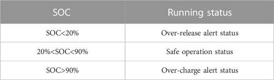
TABLE 1. Relationship between battery running status and SOC.
When a disturbance occurs in the system, such as a sudden increase in load resulting in a frequency dip, the converter on the storage unit side monitors system frequency deviation A, and if the storage unit is already in the over-discharge alert state, the discharge current needs to be controlled to 0. At this time, the storage unit cannot provide inertia support for the system, and the PV module can still work in the maximum power point tracking mode. When the energy storage unit is discharged, if it is in the low inertia zone in the figure, the energy storage unit can still provide a part of the virtual inertia for a short time until the charge state drops to the over-discharge alert zone when the discharge stops, the virtual inertia of the low inertia zone can be expressed as follows:
Likewise, if when a disturbance occurs in the system, such as a sudden load reduction resulting in a rise in frequency, the energy storage unit side converter monitors the amount of change in the system frequency Δf>0.A The operating state is first determined by the SOC state of the energy storage unit. If the energy storage unit is in the overcharge alert zone state, the control energy storage unit charging current is 0, at which time the energy storage unit can no longer provide inertial support. When the energy storage unit is charging, if it is in the low inertia zone in the figure, the energy storage unit can still charge to provide a part of inertial support until the charge state rises to the overcharged alert zone when the energy storage unit stops working. The virtual inertia of this low inertia zone can be expressed as follows:
When load fluctuation occurs in the system, it will cause the grid frequency to oscillate. If the regulation is only based on the aforementioned virtual synchronous generator control, although it can maintain the stability of the AC grid bus, the inertia support it provides for the system is a constant value and the system frequency changes at any time, so it cannot provide inertia support flexibly according to the system frequency change. Based on this problem, this project designs an adaptive inertia control that considers the speed and degree of the system frequency change, and its control method is shown in Figure 4.
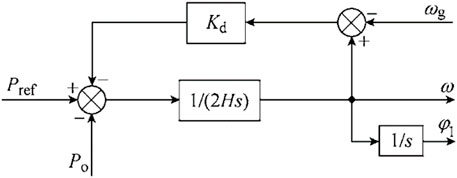
FIGURE 4. Adaptive inertial control structure.
In this paper, on the basis of the original VSG control method and synchronous motor swing equation, the rate of change and the amplitude of change in the process of frequency fluctuation when disturbance occurs in the system are considered comprehensively to determine the adaptive inertia time constant for virtual inertia control of new energy.
When the battery is in normal operation, the effect of the SOC on the virtual inertia H can be neglected, but the effects of the rate and amplitude of frequency change, converter capacity, and maximum instantaneous power can be considered. When the frequency change speed is higher and the frequency deviation is larger, it will cause the instantaneous exchange power to be very high and the amount of active change to increase; at this time, H should be increased to improve the inertia of the lifting system so as to reduce the burden on the converter, and to avoid the power change being too large and leading to the collapse of the system.
Therefore, the expression of the virtual inertial parameter H is proposed for different working states of the battery:
1) When the system energy storage SOC satisfies 20%<SOC<90%, the system inertia adaptive coefficient expression designed in this paper is as follows, considering the speed and amplitude of the frequency change of the system:
where A is determined by the difference in the degree of frequency change of the following systems:
where H0 is the size of the inertia of the system in normal operation, k1 and k2 are the adjustment coefficients, the value of A is determined by the aforementioned formula, Δkx is the parameter adjustment step, and β and Δf are the system frequency fluctuation threshold and the system frequency limited maximum fluctuation value, respectively.
2) When the system energy storage SOC satisfies SOC<20%, if the battery is still discharged normally in this state, it will greatly deplete its service life, at this time, according to the energy storage components SOC to regulate its inertial support of the system as follows:
where k3 and B are the adjustment factors for the system energy storage at SOC <20%.
3) When the system energy storage SOC satisfies SOC>90%, the battery reaches its charging limit state; in this state, still, normal charging will greatly deplete its service life. At this time, according to the energy storage element SOC to adjust its inertia support to the system
where k4 and C are the adjustment factors for the system energy storage at SOC>90%.
In summary, when SOC constraints of the energy storage device and the speed and degree of change of the system frequency are considered, the systematic equivalent inertia provided to the system by the distributed generation and energy storage system when the frequency oscillates can be adjusted as follows:
where k1, k2, k3, B, and C are the adjustment factors used according to different SOC states.
By observing Eq. 18, it can be found that |df/dt| and H present a positive correlation; |Δf| and H present a negative correlation; and Pt and H present a negative correlation. In other words, H increases with the increase in |df/dt| and decreases with the increase in |Δf| and Pt, and the trend is consistent with the actual engineering requirements. When the effect of the SOC of the energy storage device is ignored, this VSG control strategy can adjust the control parameters in the form of the power function and exponential function to improve the dynamic response of the system to perturbations. When the energy storage unit is in the limit operation state, the control strategy can self-adaptively adjust H based on SOC to ensure that the lifetime of the energy storage device is extended under the premise of safe and stable operation of the system. Moreover, when the SOC of the energy storage device is in safe operation, this adaptive VSG control method responds to the perturbation better than the conventional VSG control, which can improve the system operation status.
As described previously, the proposed control procedure for the adaptive VSG control strategy can be provided, as shown in Figure 5. According to Figure 5, the virtual inertia parameter H can be corrected in time as the constraints change. This is the advantage and key of this adaptive VSG control strategy. It is worth noting that this constraint includes SOC of the energy storage device, frequency change rate, and frequency deviation, among others. Then, the VSG system can adapt to various operating states of the energy storage device utilizing that adaptive control. The response speed and system stability of the VSG can also be improved.
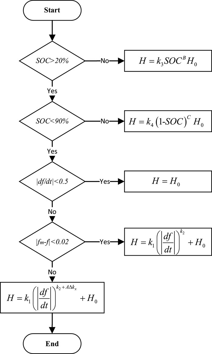
FIGURE 5. Flowchart of adaptive virtual inertia control.
The effectiveness of this adaptive VSG control method is demonstrated using a common microgrid containing PV and energy storage as the research object, and a grid-connected simulation model of PV-storage microgrid is built in PLECS, as shown in Figure 2. The specific simulation parameters are shown in Table 2. In this example, the AC bus frequency variation of the system access load at 1s under the normal SOC state condition of the energy storage unit is considered to compare the actual effect of the conventional VSG control method and the adaptive VSG control method. The simulation results are shown in Figures 6–8. The variation of conventional VSG control and adaptive VSG control in terms of virtual inertia is given in Figure 9 when the system AC bus frequency is varied.
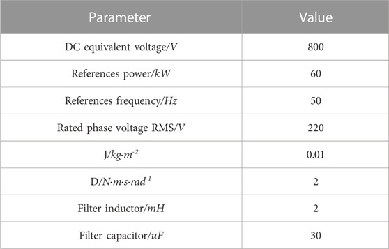
TABLE 2. Model parameters.
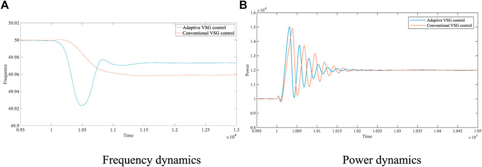
FIGURE 6. Frequency and power dynamics with 20-kW disturbance. (A) Frequency dynamics. (B) Power dynamics.
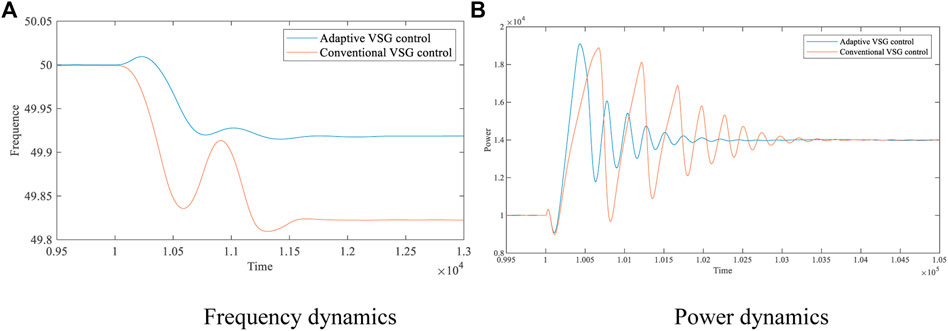
FIGURE 7. Frequency and power dynamics with 40-kW disturbance. (A) Frequency dynamics (B) Power dynamics.
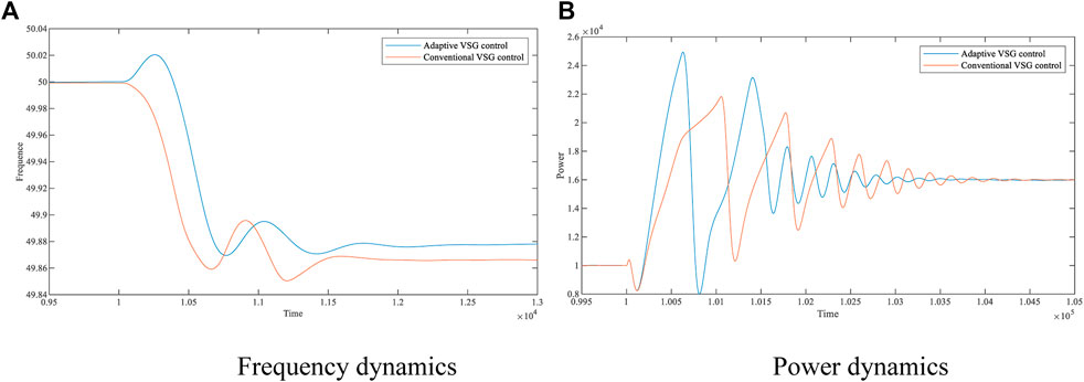
FIGURE 8. Frequency and power dynamics with 60-kW disturbance. (A) Frequency dynamics. (B) Power dynamics.
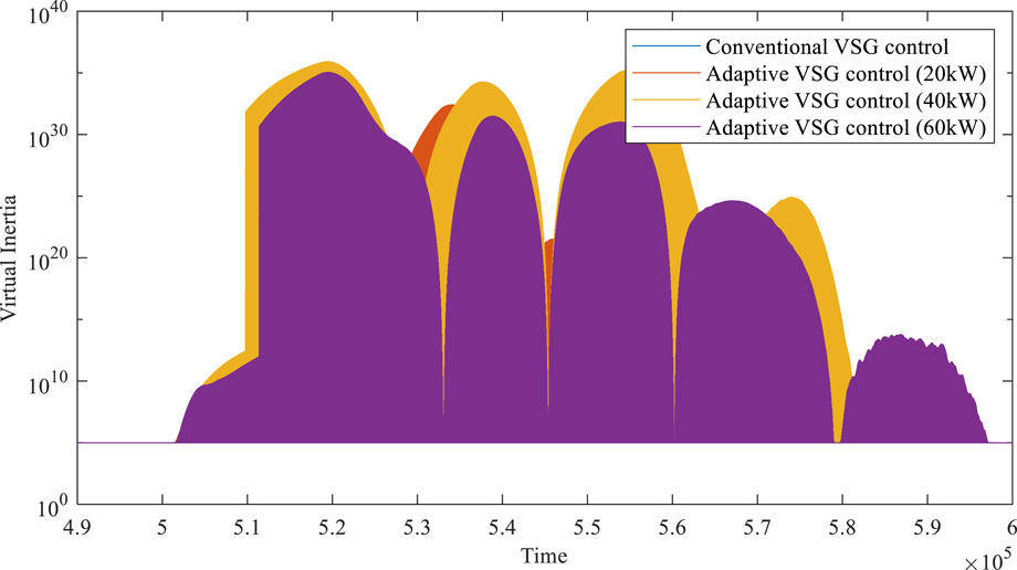
FIGURE 9. Changes of system inertia under different disturbances.
Different load disturbances of 20, 40, and 60 kW are connected to the grid with the conventional VSG control and adaptive VSG control methods at 1s, where the adjustment coefficients in the adaptive parameters are: k1 = 2, k2 = 5, Δkx = 8, β = 0.5, and Δf = 0.02. The results obtained in the PLECS simulation are shown as follows.
Table 3–5 compares the simulation results of the conventional VSG control and the adaptive VSG control methods proposed in this paper in the area of frequency variation, frequency recovery time, and power stabilization time. The data in the table show that when the system undergoes a 20-kW load fluctuation, the frequency increases from 49.9591 Hz to 49.9733 Hz, resulting in an improvement of 34.72%; the frequency recovery time decreases from 0.1193 s to 0.10065 s, resulting in a reduction of 15.63%; and the power stabilization time decreases from 0.21025s to 0.15585s, resulting in a reduction of 25.87%. When the system undergoes 40-kW load fluctuation, the frequency increases from 49.8222 Hz to 49.9194 Hz, leading to an increase of 54.67%; the frequency recovery time decreases from 0.2934 s to 0.2198 s, leading to a decrease of 25.09%; and the power stabilization time decreases from 0.2053 s to 0.1565s, leading to a decrease of 23.77%. When the system undergoes 60 kW load fluctuation, the frequency increases from 49.8609 Hz to 49.8788 Hz, resulting in an improvement of 12.87%; the frequency recovery time decreases from 0.37225 s to 0.2943 s, resulting in a reduction of 20.94%; and the power stabilization time decreases from 0.31565 s to 0.25855 s, resulting in a reduction of 18.09%. It is verified that the adaptive VSG control method can reduce transient fluctuations caused by load fluctuations on the AC side.
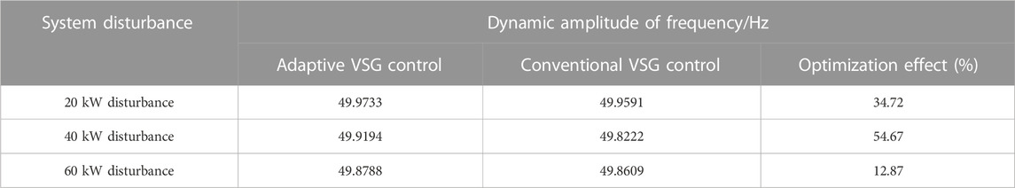
TABLE 3. Dynamic amplitude results for frequency.
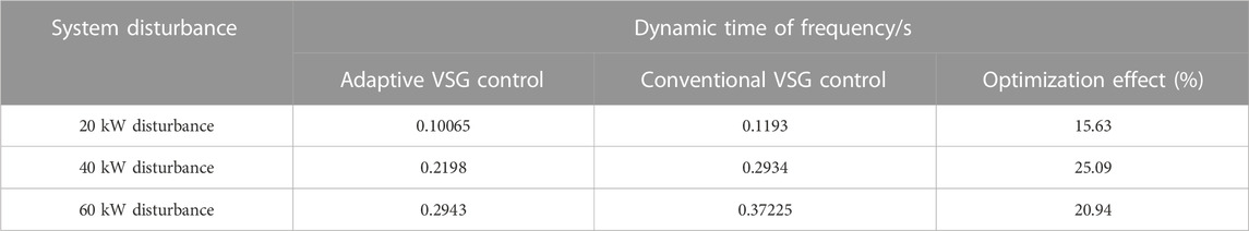
TABLE 4. Dynamic time results for frequency.

TABLE 5. Dynamic time results for power.
The semi-physical and HIL experimental platforms shown in Figure 10 are constructed to verify the effectiveness of the adaptive VSG control method. The semi-physical experimental platform consists of four parts: the RTBox real-time simulation bench, the DSP control board, the host computer, and the oscilloscope. The DC voltage source, DC/AC inverter, LC filter, and load are built inside the RTBox, while the adaptive VSG control method proposed and the conventional VSG control method are deployed in the DSP controller, which captures the analog DC voltage and AC voltage output from the RTBox through the adapter board and generates the PWM drive signal through internal calculation. The digital input port of the RTBox captures the PWM drive signal, which drives the internal power electronics to operate normally. RTBox has 16 analog I/O ports and 32 digital I/O ports, which satisfy the demand for signal ports in this experiment. The oscilloscope shows the output frequency waveform and output power waveform of VSG by connecting the analog output channel of RTBox. TI’s TM320F28069 is used as the main control chip of the DSP control board in the semi-physical experiment.
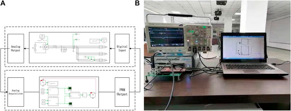
FIGURE 10. Hardware-in-the-loop experimental platform. (A) Hardware-in-the-loop experimental platform design block diagram. (B) Hardware-in-the-loop experimental platform physical picture.
Figures 11, 12 represent the system frequency dynamics and power dynamics when a load disturbance occurs, respectively. As can be seen from the data in the figures, the frequency deviation increases from 49.91 Hz to 49.95 Hz, having an improvement of 37.5%; the frequency stabilization time decreases from 78.2 ms to 14.5 ms, having an improvement of 18.5%; and the power stabilization time decreases from 124 ms to 60 ms, having an improvement of 51.6%. This is in general agreement with the data shown in Table 3. By comparing the experimental results of the conventional VSG control methods with the constant inertia with the adaptive inertia VSG control strategy, it can be seen that the adaptive VSG control method proposed in this paper can bring the system to a steady state more quickly when different system loads change while making the new steady-state frequency value of the system closer to the reference frequency with less variation. It is verified that the adaptive VSG control method proposed is still effective in HIL experiments and can be optimized for transients caused by load fluctuations on the AC side, which is of good practical value.
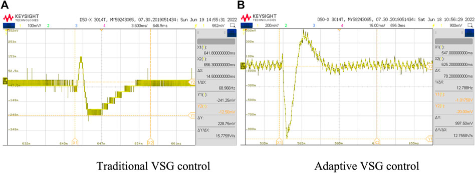
FIGURE 11. Frequency dynamics with load disturbance. (A) Traditional VSG control. (B) Adaptive VSG control.
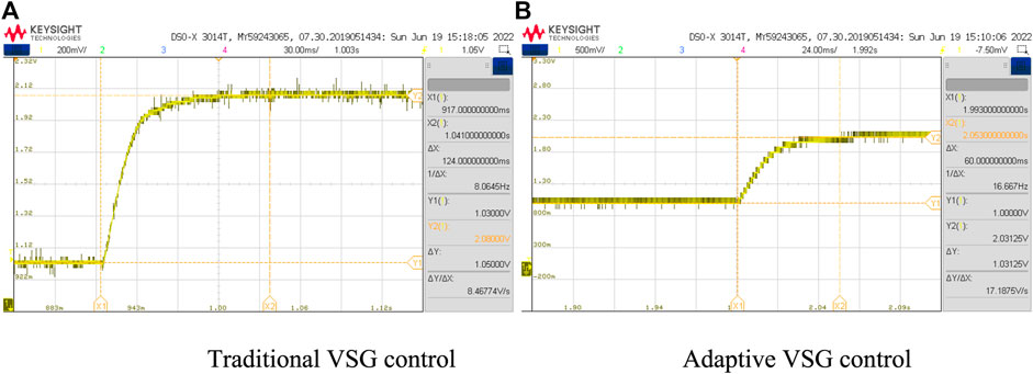
FIGURE 12. Power dynamics with load disturbance. (A) Traditional VSG control. (B) Adaptive VSG control.
This paper takes the photovoltaic energy storage system as the research object; the inertia support problem of the distributed generation system is solved by an adaptive VSG control method. When evaluating the equivalent inertia, an adaptive VSG control method is proposed to keep the system frequency oscillations, which prolongs the service life of the energy storage unit while ensuring the safe and stable operation of the system. Different from the conventional VSG control strategy, the adaptive VSG control method proposed in this paper considers the two ultimate operating conditions of the energy storage device, adjusts the virtual inertia according to the rate and degree of frequency change to accelerate the system frequency recovery, and provides inertia support for the system while reducing damage to the energy storage components caused by overcharging and discharging, and the lifetime of the energy storage unit is extended.
On the basis of analyzing the equivalent rotational inertia of the system and the frequency support capability of the energy storage element, the SOC state of the energy storage element is divided and the inertia is evaluated by considering the damage of the service life of the energy storage element due to extreme operation, when the energy storage element operates within the safe charging and discharging region by considering the system frequency change rate and frequency change degree. On the other hand, the A value determined by the difference between the real-time frequency and the reference frequency, combined with the adjustment step, will increase the inertia by increasing the adaptive index when the amplitude of the system frequency change value exceeds the set value. Finally, this paper builds a four-terminal optical storage microgrid model, compares the control effects of different VSG strategies through simulation, and uses RTBox to build a HIL experimental platform. The results show that the adaptive VSG control method proposed in this paper can actively adjust the magnitude of the virtual inertia in real time based on the frequency changes, thus improving the stable operation performance of the system and increasing the service life of the converters, energy storage units, and other equipment.
The original contributions presented in the study are included in the article/Supplementary Material. Further inquiries can be directed to the corresponding author.
JH: funding acquisition, methodology, project administration, and writing–original draft. XF: formal analysis, software, and writing–original draft. HZ: writing–review and editing. PH: supervision, validation, and writing–review and editing. CH: investigation, resources, and writing–review and editing.
The author(s) declare financial support was received for the research, authorship, and/or publication of this article. This study was supported by a grant from the State Grid Hebei Electric Power Co., LTD. (Research on key technology of operation control of photovoltaic-energy storage integrated generator actively supporting new power system, SGHEJYOOGHJS2200056). The funder had the following involvement in the study:Provided data support and HIL experimental design.
JH, XF, and CH were employed by the State Grid Hebei Economic Research Institute. JH, HZ, and PH were employed by the State Grid Hebei Electric Power Co., LTD.
All claims expressed in this article are solely those of the authors and do not necessarily represent those of their affiliated organizations, or those of the publisher, the editors, and the reviewers. Any product that may be evaluated in this article, or claim that may be made by its manufacturer, is not guaranteed or endorsed by the publisher.
Arco, S. D., Suul, J. A., and Fosso, O. B. (2015). A Virtual Synchronous Machine implementation for distributed control of power converters in SmartGrids. Electr. Power Syst. Res. 122 (6), 180–197. doi:10.1016/j.epsr.2015.01.001
Beck, H., and Hesse, R. (2007). Virtual synchronous machine. Barcelona, Spain: IEEE 9th International Conference on Electrical Power Quality and Utilisation, 1–6. doi:10.1109/EPQU.2007.4424220
Chen, H., Zhang, C., Miu, H., Yang, Y., and Zheng, J. (2018). Virtual synchronous generator system with battery SOC feedback control. Electr. Power Eng. Technol. (4), 90–96. doi:10.19464/j.cnki.cn32-1541/tm.2018.04.015
Deng, X., Sun, W., and Xiao, H. (2018). Integrated control strategy of battery energy storage system in primary frequency regulation. High. Volt. Eng. 44 (4), 1157–1165. doi:10.13336/j.1003-6520.hve.20180329015
Hammad, E., Farraj, A., and Kundur, D. (2017). On effective virtual inertia of storage-based distributed control for transient stability. IEEE Trans. Smart Grid 10 (1), 327–336. doi:10.1109/TSG.2017.2738633
He, D. (2015). Control of photovoltaic-based micro-grid with virtual synchronous generator. Electr. Energy Manag. Technol. (10), 46–50. doi:10.16628/j.cnki.2095-8188.2015.10.015
Hu, A., Yang, B., Pan, P., Li, G., Tao, Y., and Chen, W. (2018a). Study on inertial characteristics of energy storage system with power electronic interface. Proc. CSEE 38 (17), 4999–5008. doi:10.13334/j.0258-8013.pcsee.172143
Hu, W., Wu, Z., Sun, C., Song, Y., Yuan, K., and Wang, Y. (2018b). Vertebral column decancellation in pott's deformity: use of surgimap spine for preoperative surgical planning, retrospective review of 18 patients. Electr. Power Autom. Equip. 38 (8), 13–23. doi:10.1186/s12891-018-1929-6
Jiang, S., Peng, K., Xu, B., Zhang, X., and Liu, Y. (2021). Current situation and prospect of demonstration projects of DC distribution system. Electr. Power Autom. Equip. 41 (05), 219–231. doi:10.16081/j.epae.202105039
Li, Y., Guo, X., Dong, H., and Liu, C. (2020). VSG control strategy for adaptive rotational inertia in island micro-grid. Proc. CSU-EPSA 203 (12), 144–150. doi:10.19635/j.cnki.csu-epsa.000499
Li, Y., Zhang, J., and Wang, N. (2017). A management control strategy of photovoltaic-storage system based on virtual synchronous generator. Mod. Electr. Power 34 (05), 64–73. doi:10.19725/j.cnki.1007-2322.2017.05.010
Li, Z., Wu, L., Wang, L., and Yang, N. (2023). Distributed tri-layer risk-averse stochastic game approach for energy trading among multi-energy microgrids. Appl. Energy, Elsevier 331, 282. doi:10.1016/j.apenergy.2022.120282
Lv, Z., Luo, A., Jiang, W., and Xu, X. (2012). New circulation control method for micro-grid with multi-inverter micro-sources. Trans. China Electrotech. Soc. 27 (1), 40–47. doi:10.19595/j.cnki.1000-6753.tces.2012.01.006
Qu, Z., Cai, Y., Yang, H., Dong, N., Zhao, R., and Han, J. (2018). Strategy of power decoupling control for virtual synchronous generator based on adaptive virtual impedances. Automation Electr. Power Syst. 42 (17), 58–66. doi:10.7500/AEPS20171114014
Sakimoto, K., Miura, Y., and Ise, T. (2011).Stabilization of a power system with a distributed generator by a virtual synchronous generator function [C]. Power electronics and ECCE asia (ICPE and ECCE)IEEE 8th International Conference on, 9-12 Dec. 2022, USA. IEEE, 1498–1505. doi:10.1109/ICPE.2011.5944492
Shi, R., Zhang, X., Liu, F., Xu, H., and Yu, Y. (2016). Control technologies of multi-energy complementary microgrid operation based on virtual synchronous generator. Trans. China Electrotech. Soc. 31 (20), 170–180. doi:10.13334/j.0258-8013.pcsee.172143
Visscher, K., and De Haan, S. W. H. (2008). Virtual synchronous machines (VSG’s) for frequency stabilization in future grids with a significant share of decentralized generation. Smart Grids Distribution, 1–4.
Wang, M. (2021). Research on control technology of PV and energy storage power generation system based on VSM. China: China University of Mining and Technology. doi:10.27623/d.cnki.gzkyu.2021.002082
Wang, S., Hu, J., Yuan, X., and Sun, L. (2015). On inertial dynamics of virtual-synchronous-controlled DFIG based wind turbines. IEEE Trans. Energy Convers. 30 (4), 1691–1702. doi:10.1109/TEC.2015.2460262
Wang, S., Ge, B., and Bi, D. (2011). Control strategies of grid-connected wind farm based on virtual synchronous generator. Power Syst. Prot. Control 39 (21), 49–54.
Xin, L., Dan, W., Tao, Z., et al. (2015).Energy management strategy of battery in isolated micro-grid based on state of charge (SOC), International Conference on Biomedical Engineering and Informatics, October 17-19, 2020, New York. IEEE, 879–884. doi:10.1109/BMEI.2014.7002896
Yu, J., Meng, J., Wang, K., Liu, H., and Liu, D. (2021).Research on the control strategy of hybrid energy storage cooperative operation based on VSG control, International Conference on Power System Technology (POWERCON), 12 – 14 September 2022. Haikou, China: IEEE, 1189–1195.
Yuan, C., Liu, C., Zhao, T., Chen, M., and Xiao, X. (2017). Research on operating boundary of virtual synchronous machine based on physical constraint of energy storage system. Proc. CSEE 37 (02), 506–516. doi:10.13334/j.0258-8013.pcsee.161121
Zeng, Z., Shao, W., Ran, L., Lv, Z., and Li, R. (2015). Mathematical model and strategic energy storage selection of virtual synchronous generators. Automation Electr. Power Syst. 39 (13), 22–31. doi:10.7500/AEPS20140901007
Zhang, C., Cai, X., Li, Z., Xu, X. d., Su, H., Cheng, X. H., et al. (2017b). Control of DFIG-based wind turbines with the capability of automatic grid-synchronization and stable operation under weak grid condition. Proc. CSEE 37 (02), 476–484. doi:10.13227/j.hjkx.201608043
Zhang, X., Li, L., and Bian, Z. (2019). Virtual moment inertia control based on hybrid static energy storage. Electr. Power Autom. Equip. 39 (11), 50–56. doi:10.16081/j.epae.201911003
Zhang, X., Yang, L., Zhu, X., and Fu, Y. (2017a). Virtual rotational inertia control of PV generation system with energy storage devices. Electr. Power Autom. Equip. 37 (9), 109–115. doi:10.16081/j.issn.1006-6047.2017.09.015
Zheng, T., Chen, L., Chen, T., and Mei, W. (2015). Review and prospect of virtual synchronous generator technologies. Automation Electr. Power Syst. 39 (21), 165–175. doi:10.7500/AEPS20150508006
Zheng, T., Chen, L., Liu, W., Guo, Y., and Mei, L. (2017). Multi-mode operation control for photovoltaic virtual synchronous generator considering the dynamic characteristics of primary source. Proc. CSEE 37 (02), 454–464. doi:10.13334/j.0258-8013.pcsee.161657
Zhong, Q., and Weiss, G. (2010). Synchronverters: inverters that mimic synchronous generators. IEEE Transaction Industrial Electron. 58 (4), 1259–1267. doi:10.1109/TIE.2010.2048839
Zhu, Z., Huang, S., Li, Z., and Shao, Y. (2020). Research on control strategy for micro-grid adaptive rotating inertia virtual synchronous generator. Proc. CSU-EPSA 195 (04), 111–115. doi:10.19635/j.cnki.csu-epsa.000275
Keywords: virtual synchronous generator control, optical storage unit, state of charge constraint, adaptive control, virtual inertia, semi-physical simulation experiments, hardware-in-the-loop experiments
Citation: Han J, Feng X, Zhao H, Hu P and He C (2023) Adaptive VSG control strategy considering energy storage SOC constraints. Front. Energy Res. 11:1278648. doi: 10.3389/fenrg.2023.1278648
Received: 16 August 2023; Accepted: 28 August 2023;
Published: 18 September 2023.
Edited by:
Zhengmao Li, Aalto University, FinlandCopyright © 2023 Han, Feng, Zhao, Hu and He. This is an open-access article distributed under the terms of the Creative Commons Attribution License (CC BY). The use, distribution or reproduction in other forums is permitted, provided the original author(s) and the copyright owner(s) are credited and that the original publication in this journal is cited, in accordance with accepted academic practice. No use, distribution or reproduction is permitted which does not comply with these terms.
*Correspondence: Xichun Feng, Z3d4bXRneTIwMjIgQDE2My5jb20=
Disclaimer: All claims expressed in this article are solely those of the authors and do not necessarily represent those of their affiliated organizations, or those of the publisher, the editors and the reviewers. Any product that may be evaluated in this article or claim that may be made by its manufacturer is not guaranteed or endorsed by the publisher.
Research integrity at Frontiers
Learn more about the work of our research integrity team to safeguard the quality of each article we publish.