 Xinyu Zhang1,2
 Yan Zhao
 He Jiang
- 1School of Renewable Energy, Shenyang Institute of Engineering, Shenyang, China
- 2Liaoning Key Laboratory of Regional Multi-Energy System Integration and Control, Shenyang, China
- 3School of Electrical Engineering, Shenyang University of Technology, Shenyang, China
This paper introduces a novel control strategy that merges integral sliding mode control with fuzzy adaptive PI control. This hybrid approach maximizes the benefits of both techniques to ensure voltage stability in DC microgrid. Firstly, a mathematical model characterizes the DC–DC boost converter. Subsequently, a sliding surface, incorporating an integral term, is employed to regulate the converter’s output voltage and current errors. To address uncertainties stemming from factors like input inductance and output capacitance, a dynamic sliding mode controller is formulated. The proposed sliding mode control scheme significantly reduces the time required for voltage stability, curbs system oscillations, and showcases robustness. Furthermore, the inclusion of fuzzy adaptive PI control aids in refining the voltage deviation signal and droop resistance. This enhancement improves the precision of the error tracking system. Finally, the effectiveness of this strategy is demonstrated through MATLAB simulations, supported by experimental validation and analysis. The findings reveal that this control strategy efficiently accelerates the convergence of DC microgrid voltage to a stable state.
1 Introduction
A microgrid can be conceptualized as an integrated power system that encompasses distributed generation systems, loads, and energy storage devices (Ullah et al., 2022). The growing adoption of microgrids is attributed to their heightened reliability, improved economic considerations and reduced global warming impact. The DC microgrid, in particular, has garnered significant attention and research interest in the realm of power engineering owing to its distinct advantages and potential. When contrasted with AC microgrids, DC microgrids offer enhanced reliability, efficiency, and reduced power conversion losses. Additionally, a majority of loads in modern residential and industrial applications are powered by DC sources (Gui et al., 2021; Saafan et al., 2023). Consequently, DC microgrids hold appeal as integral components within contemporary intelligent power systems (Prabhakaran and Agarwal, 2020).
In the current context, with the focal point on sustainable energy and energy efficiency, the significance of DC–DC converters in electrical engineering and microgrid design has gained further prominence (Wang et al., 2020). These converters play a pivotal role in connecting the DC output of renewable energy sources to the distribution system, owing to their cost-effectiveness, straightforward structure, and efficient power conversion performance. This aspect holds vital importance in optimizing energy utilization and enhancing energy efficiency at the user end (Haroun et al., 2015; Tiwary et al., 2023). The fundamental control objectives of a DC microgrid encompass skillful power distribution management and meticulous bus voltage regulation (Li et al., 2021). Prolonged substantial deviations in output voltage can precipitate system instability, necessitating the introduction of stabilizing control methodologies.
Regarding the stability quandary of boost converters, an array of advanced control strategies have been proposed, including proportional resonant (PR) control, proportional integral derivative (PID) control, fuzzy logic-based control, and repetitive control (Zheng et al., 2018). Among these control strategies mentioned above, sliding mode control is considered to be a very efficient nonlinear robust control method due to its large stabilization range, rapid dynamic response, and strong disturbance immunity (Wang et al., 2021; Linares-Flores et al., 2022). In (Liu et al., 2011), the authors designed two control loops containing different converters which involve variable charging and discharging modes to enhance the productivity of a hybrid power system. The designed method, although it has improved the efficiency of the system, employs electrical components such as bi-directional converters and inductors that are too idealized and do not take into account the presence of uncertainties at the same time, which does not achieve a fast tracking of the errors. Literature (Mao et al., 2022) tries to solve this problem by incorporating T-S fuzzy control when dealing with nonlinear state variables, so as to improve the utilization of PV cells connected to the microgrid while maintaining the stability of the bus voltage, but the procedure is relatively time consuming. The maintenance of system stability is an important task in control theory. In traditional discontinuous control theory, the generation of control rates usually relies on sign functions or hysteresis modulators and in this way ensures the stability of the system. These generated control laws must satisfy certain specific inequality conditions (Biricik and Komurcugil, 2016; Merabet et al., 2017) to ensure their validity. However, a noteworthy issue is that this control strategy still suffers from output chattering. This may negatively affect the system performance, especially in applications with high precision control or high dynamic response. To address this issue, researchers have started to consider the use of smoothing control law to eliminate the vibration problem of discrete-time sliding mode control. This is an effective strategy, which can suppress the chattering to a certain extent and thus improve the system performance. However, the smoothing control law is not without problems. The primary problem is that this control method may limit the regulation capability and dynamic response of the converter. Literature (Inomoto et al., 2022) provides a solution to the above problem by designing two control loops in the sliding mode controller. The first is an input voltage control loop for computing the inductive current, guided by the MPPT algorithm. The second circuit controls the current, which is related to the duty cycle of the switches. These two loops enhance the performance of the converter. The proposed technique uses a smooth switching function to avoid chattering, resulting in a substantial shortening of the time to reach a steady state. However, the literature selects high-order sliding surfaces, which leads to the drawback of overly complex algorithmic calculations.
The means for treating system uncertainties and variations are not only sliding mode control, the adaptive PI control and fuzzy control are also often in the priority list. Literature (Mi et al., 2019) incorporates a T-S fuzzy model in a sliding mode controller designed for the DC microgrid. Since the relationship between the output voltage and power of distributed power sources is nonlinear, the T-S fuzzy model is introduced for processing. The sliding mode droop control is used to improve the vibration resistance of the system due to parameter uncertainties and variations in operating conditions. This combination enables the system to be more accurate when allocating power according to the load. In the literature (Ahmed et al., 2018), the author addresses the occurrence of phenomena such as short-circuits or abrupt changes in load during the operation of power electronic devices. A fuzzy logic control was integrated into the coefficients of traditional PI controllers, enabling the controller to rapidly respond to these changes. Taking power electronic distribution transformer as an example, the voltage and current errors are transferred to the improved PI controller and the performance of the controller in its application under different operating conditions is considered. The experiment demonstrates that the proposed controller is capable of meeting the desired requirements, but suffers from the problem of slow response time. The authors in (Mokhtar et al., 2019) employed a sliding mode controller to control the tracking error, and then added an adaptive PI controller to adjust the error-related voltage and current more accurately, but the sliding mode control portion of it was not sufficiently stable for voltage error control. Different from the previous work that only considered different control methods combined together, in the literature (Jan et al., 2020), the authors emphasized on the improvement of the parameters while applying two control methods, in which the parameters are inferred by using the affiliation function and fuzzy rule table, and genetic algorithms are also involved. Ultimately, the output power of the renewable energy source can be maximized, while these measures assure the frequency stabilization in the system. However, with this control method, unknown system parameters need to be estimated through the use of multiple adaptive laws, which leads to the over-parameterization problem. Literature (Kuppusamy and Joo, 2021) designed a memory-integrated sliding mode control based on perturbation observer using T-S fuzzy approach, which defines an integral fuzzy switching surface function containing both input matrix and implicit parameters related to the state variables, and utilizes the disturbance estimation generated by the perturbation observer to offset the mismatched disturbance error. This strategy has a T-S fuzzy modeling of the sliding mode motion, which operates according to the control model in the initial state and maintains this state continuously under the limitations of the memory sliding mode. This method is guaranteed for the fast response of the system while preserving its continuous stability.
Addressing the challenge posed by the complex and uncertain operational environment, which impedes the maintenance of a sustained steady state, this study introduces a novel sliding mode control (SMC) scheme. To secure the stable operation of the DC microgrid, an integral sliding surface is constructed, subsequently refining the traditional SMC approach. The stability of the improved SMC method is substantiated through an appropriate Lyapunov function.
The main contributions of this paper are as follows.
1) The proposed SMC effectively mitigates system chattering by incorporating an integral sliding surface design, markedly enhancing tracking performance and ensuring voltage stability;
2) An adaptive PI controller is combined to govern the error between the DC bus voltage and its reference value and the droop resistance to optimize voltage regulation. This combination yields a more precise converter output voltage;
3) Parameter tuning for the adaptive PI controller leverages fuzzy rules, allowing adaptation to varying internal and external parameters.
The rest of this paper is organized as follows. Section 2 shows the system model of the DC–DC converter. Section 3 introduces the designed sliding mode controller. Section 4 describes the fuzzy adaptive PI control. Section 5 presents the simulation results. The conclusion is illustrated in Section 6.
2 System model of the DC–DC converter
DC–DC converters are utilized in numerous applications in power systems. These converters manipulate the power electronics’ on/off states to modulate current transmission paths for voltage augmentation. Notably, boost converters offer distinct advantages across diverse scenarios. Their short duty cycles translate to comparatively low energy losses, a crucial attribute for extended-operation devices like remote communication systems, computers, and office automation equipment. Moreover, boost converters find favor in precision-demanding sectors like military and aerospace owing to their stable output voltage traits (Lee et al., 2011). In essence, the realm of DC–DC converters is characterized by diversity and multifold applications, encompassing varied types. Boost converters, specifically, have seamlessly integrated into myriad domains owing to their distinctive attributes. Figure 1 illustrates the overarching framework of the described control strategy. The mathematical representation of a DC–DC converter is given by
where
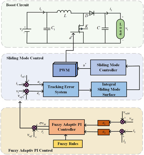
FIGURE 1. The general framework of the proposal control strategy in the DC microgrid.
3 Proposed sliding mode control
In microgrids, whether the voltage is stable or not is of especially significance for improving the performance of control accuracy and response speed, including ensuring the stable operation of microgrids. For this reason, the control approach used in this paper is the sliding mode control, where the object of control is chosen to be a tracking error system consisting of errors in output voltage and inductive current with their reference values, we introduce the following definitions:
where
where
In Eq. 4, the system state matrices
The design of the sliding surface is crucial and it directly determines the dynamic properties of the system under sliding mode motion. After the system state reaches the sliding surface, the behavior will be governed by the nature of the sliding surface. This means that the system is robust to parameter variations and external perturbations. However, the traditional sliding mode control can lead to a large chattering in the system due to the high frequency switching characteristics of the sliding surface. Hence, during the refinement of the algorithm, a consideration of how to balance the robustness in the system with the need to suppress chattering is warranted to gain an optimization of the control capability of the converter. The introduction of an integral term into the sliding surface is a mean to attenuate the high-frequency switching and consequently reduce the system vibration to a certain extent. The integral sliding surface can ensure more stable system operation. Therefore, the following sliding surface containing integral term is selected.
where
Substituting Eq. 4 into the derivative of the integral sliding surface (5) yields
The equivalent control law can be obtained by setting Eq. 6 to be zero
Taking parameter uncertainty and resistance to perturbations into account as well, the hyperbolic tangent function is adopted and the final design of the sliding mode controller is expressed as follows:
where
In this improved sliding mode controller,
In order to analyze the stability of the proposed sliding mode control, the following Lyapunov function is selected.
Differentiating the Lyapunov function and combining with Eq. 8, it yields
The above-mentioned verification indicates that the derivative of the Lyapunov function
In a high switching frequency environment, the duty cycle can be interpreted as a smooth analytic function of the discrete pulses in a pulse width modulation (PWM) control system. The duty cycle of the DC–DC boost converter is a key parameter that determines the adjustment range and stability of the output voltage. The average control motion of the sliding mode control system can theoretically be viewed as the average dynamic response of a PWM control system. However, regardless of the output of the SMC system, the actual physical meaning has a limitation on the value of the duty cycle, which must be in the region of [0, 1]. Therefore, we can design an actual duty cycle
4 Fuzzy adaptive PI control
To make the voltage error more accurate and ensure enhanced stability in the output voltage of the converter, two fuzzy adaptive PI controllers are added to the treatment of the voltage tracking error. These controllers serve to enhance precision in managing the DC bus voltage and the droop resistance, respectively. The inputs of adaptive PI controllers are the DC bus voltage error and the current distribution error. By manipulating the droop control parameters, precise control over the current allocation for each distributed generation system within the microgrid is achieved, leading to elevated power quality and microgrid reliability. The following equation presents an adaptive droop system expression:
where
where
where
In the practical operation of microgrids, due to the occurrence of sudden changes in loads, etc., the currents are not immune to additional errors, which can have an effect on the droop resistance in the droop system. We have to cope with this situation and the new droop resistance can be written by
where
While the conventional PI control approach enjoys widespread application, it exhibits poor robustness, susceptibility to voltage overshoot and current surges, and sensitivity to alterations in system parameters and nonlinear traits. Fuzzy control, in contrast, is an adaptable method not contingent upon an accurate system model. It showcases robustness, particularly when handling nonlinear systems. Nonetheless, despite the merits of fuzzy control, its performance might lag behind that of conventional PI control in certain instances. To synergize the advantages of both approaches and surmount their individual limitations, this paper combines fuzzy control with an adaptive PI controller. This combination enables online self-adjustment of PI parameters through fuzzy rules to make the parameters more accurate and flexible. The method seamlessly combines the robustness of fuzzy logic and the intuition of PI control, enabling the controller to flexibly adapt to diverse load variations and voltage fluctuations. Specifically, the engineered fuzzy adaptive PI controller initially acquires system error and error variation rate data. Subsequently, it employs a fuzzy logic system to conduct reasoning based on this information, adjusting parameters based on the outcomes. This design empowers the controller to dynamically fine-tune its performance to accommodate shifts in the system state.
The fuzzy domains of the fuzzy input variables

TABLE 1. Fuzzy rule control table of

TABLE 2. Fuzzy rule control table of
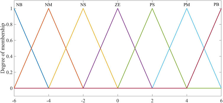
FIGURE 2. The membership function.
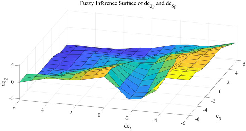
FIGURE 3. Fuzzy inference surface of
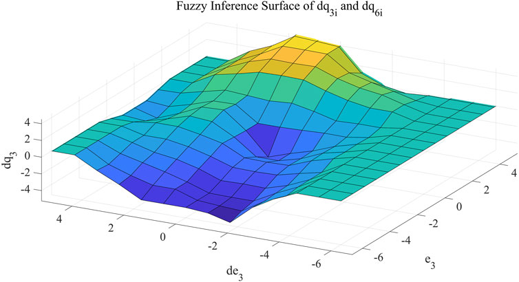
FIGURE 4. Fuzzy inference surface of
The improved adaptive parameters are expressed as follows:
where
According to the same principle, the coefficients of the second fuzzy adaptive PI controller can be obtained as follows:
where
5 Simulation results
This subsection aims to substantiate the efficacy of the proposed algorithm through simulation examples. The parameters involved in the simulation are shown in Table 3.
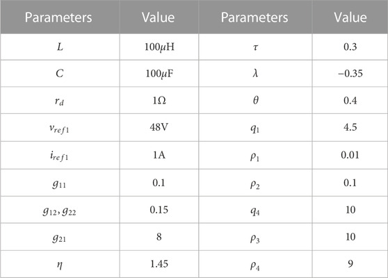
TABLE 3. System parameters.
Initially, we excluded the influence of external disturbances and solely evaluated the control performance of the proposed method under ideal circumstances. A comparison with the traditional SMC approach yielded the subsequent simulation outcomes. Referring to Figure 5 and Figure 6, we deduce that, within the confines of the control strategy, the system rapidly and effectively attains the desired target value. Notably, the proposed method exhibits a briefer regulation duration and significantly reduced chattering compared to the conventional method. In addition, the traditional SMC cannot accurately achieve the reference value of voltage. Upon examining Figure 5 and Figure 7 concurrently, it becomes evident that the traditional method fails to achieve the desired voltage value, perpetuating an enduring error. The data in Figure 8 highlights the exceptional current control capability of the strategy developed in this paper. The current error swiftly converges to be zero within a brief span, and the oscillation amplitude remains notably smaller in comparison to the traditional method. Under ideal conditions, the advanced controller advocated in this study vividly showcases its prowess in dynamic performance enhancement.
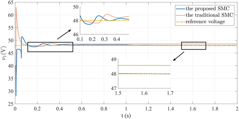
FIGURE 5. Curves of converter output voltage under ideal circumstances.

FIGURE 6. Curves of converter inductive current under ideal circumstances.
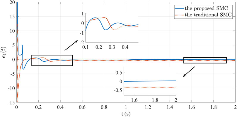
FIGURE 7. Curves of voltage error in the DC–DC converter under ideal circumstances.
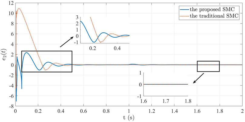
FIGURE 8. Curves of current error in the DC–DC converter under ideal circumstances.
To emulate real power system conditions, scenarios involving external disturbances were examined. Load variations were tested and discussed across different cases, with a comparison made to the performance of the traditional SMC method in these conditions. The ensuing simulation findings are presented as follows. Analyzing Figure 9, we infer that when external interference is present, the system tracks the predefined reference value quickly and effectively after changing the load, achieving regulation within 0.1 s. Figure 9 highlights that sizeable external disturbances induce more pronounced voltage fluctuations and changes under traditional SMC. This observation underscores the traditional method’s inferior robustness and diminished anti-interference capacity. In contrast, the control strategy proposed herein swiftly stabilizes the system’s output voltage, rapidly restoring equilibrium post-referential attainment. This exemplifies the strategy’s enhanced robustness and its capacity to suppress the influence of external disturbances, thereby effectually advancing system control. Figure 10 presents the current variation. Although both methods can achieve the set reference value, the proposed method restrains the chattering. Figure 11 visually illustrates the voltage error, manifesting the error’s eventual convergence to be zero under the controller’s influence. This outcome underscores the effective asymptotic tracking capability of the current control strategy. In contrast, traditional SMC fail to converge the voltage error to be zero. Figure 12 illustrates current tracking error evolution. Notably, the traditional SMC method exhibits substantial performance deviations when faced with external disturbances. The proposed SMC enables the current error to reach the convergence state more quickly and steadily.
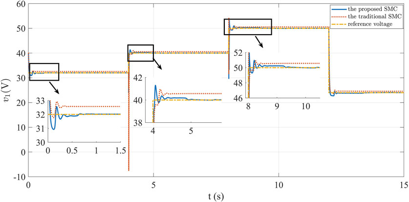
FIGURE 9. Dynamic curves of converter output voltage.
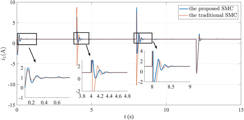
FIGURE 10. Dynamic curves of converter inductive current.

FIGURE 11. Curves of voltage error in the DC–DC converter.
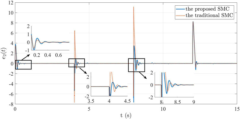
FIGURE 12. Curves of current error in the DC–DC converter.
The simulation outcomes decisively showcase the proposed controller’s pronounced improvements in both response time and precision, when juxtaposed with the conventional sliding mode controller. This method streamlines the algorithm, enhances voltage stability control, and optimizes overall system performance. These results affirm the effectiveness and superiority inherent in combining SMC and fuzzy adaptive PI control within DC–DC boost converter control.
6 Conclusion
This study proposes a voltage stabilization control strategy for DC–DC converters within DC microgrids, employing integral SMC and fuzzy adaptive PI control. The strategy effectively addresses the challenge of achieving rapid and steady output voltage states. The primary aim is to enhance dynamic performance and attain exceptional tracking error control, thereby elevating converter efficiency. The proposed SMC scheme demonstrates robust performance in countering external disturbances and voltage fluctuations. Incorporating fuzzy adaptive PI control bolsters system adaptability. The controller’s capacity to dynamically adjust PI controller gains equips the system to respond adeptly to sudden parameter changes. The strategy was validated through MATLAB simulations, confirming its ability to swiftly stabilize voltage and attenuate oscillations. In conclusion, this paper presents an innovative and effective control approach for DC–DC converters in DC microgrids. The proposed method can be widely used in voltage stabilization control in DC microgrids. Future exploration of applying this strategy to more complex power electronic devices holds promise.
Data availability statement
The raw data supporting the conclusion of this article will be made available by the authors, without undue reservation.
Author contributions
XZ: Resources, Software, Writing–original draft. YZ: Investigation, Writing–original draft. HJ: Methodology, Validation, Writing–review and editing. MW: Formal Analysis, Validation, Writing–review and editing.
Funding
The author(s) declare financial support was received for the research, authorship, and/or publication of this article. Applied Foundational Research Plan Project of Liaoning Province (2022JH2/101300218).
Acknowledgments
The authors acknowledge the technical support from 2023 Innovation and Entrepreneurship Training Program for College Students (202311632004).
Conflict of interest
The authors declare that the research was conducted in the absence of any commercial or financial relationships that could be construed as a potential conflict of interest.
Publisher’s note
All claims expressed in this article are solely those of the authors and do not necessarily represent those of their affiliated organizations, or those of the publisher, the editors and the reviewers. Any product that may be evaluated in this article, or claim that may be made by its manufacturer, is not guaranteed or endorsed by the publisher.
References
Ahmed, K. Y., Yahaya, N. Z. B., Asirvadam, V. S., Saad, N., Kannan, R., and Ibrahim, O. (2018). Development of power electronic distribution transformer based on adaptive PI controller. IEEE Access 6, 44970–44980. doi:10.1109/ACCESS.2018.2861420
Biricik, S., and Komurcugil, H. (2016). Optimized sliding mode control to maximize existence region for single-phase dynamic voltage restorers. IEEE Trans. Industrial Inf. 12, 1486–1497. doi:10.1109/TII.2016.2587769
Gui, Y., Han, R., Guerrero, J. M., Vasquez, J. C., Wei, B., and Kim, W. (2021). Large-signal stability improvement of DC–DC converters in DC microgrid. IEEE Trans. Energy Convers. 36, 2534–2544. doi:10.1109/TEC.2021.3057130
Haroun, R., Aroudi, A. E., Cid-Pastor, A., Garcia, G., Olalla, C., and Martínez-Salamero, L. (2015). Impedance matching in photovoltaic systems using cascaded boost converters and sliding-mode control. IEEE Trans. Power Electron. 30, 3185–3199. doi:10.1109/TPEL.2014.2339134
Inomoto, R. S., Monteiro, J. R. B. D. A., and Filho, A. J. S. (2022). Boost converter control of PV system using sliding mode control with integrative sliding surface. IEEE J. Emerg. Sel. Top. Power Electron. 10, 5522–5530. doi:10.1109/JESTPE.2022.3158247
Jan, M. U., Xin, A., Abdelbaky, M. A., Rehman, H. U., and Iqbal, S. (2020). Adaptive and fuzzy PI controllers design for frequency regulation of isolated microgrid integrated with electric vehicles. IEEE Access 8, 87621–87632. doi:10.1109/ACCESS.2020.2993178
Kuppusamy, S., and Joo, Y. H. (2021). Memory-based integral sliding-mode control for T–S fuzzy systems with PMSM via disturbance observer. IEEE Trans. Cybern. 51, 2457–2465. doi:10.1109/TCYB.2019.2953567
Li, X., Jiang, W., Wang, J., Wang, P., and Wu, X. (2021). An autonomous control scheme of global smooth transitions for bidirectional DC–DC converter in DC microgrid. IEEE Trans. Energy Convers. 36, 950–960. doi:10.1109/TEC.2020.3020127
Lee, J. Y., Jeong, Y. S., and Han, B. M. (2011). An isolated DC/DC converter using high-frequency unregulated $LLC$ resonant converter for fuel cell applications. IEEE Trans. Industrial Electron. 58, 2926–2934. doi:10.1109/TIE.2010.2076311
Linares-Flores, J., Juárez-Abad, J. A., Hernandez-Mendez, A., Castro-Heredia, O., Guerrero-Castellanos, J. F., Heredia-Barba, R., et al. (2022). Sliding mode control based on linear extended state observer for DC-to-DC buck-boost power converter system with mismatched disturbances. IEEE Trans. Industry Appl. 58, 940–950. doi:10.1109/TIA.2021.3130017
Liu, W. S., Chen, J. F., Liang, T. J., and Lin, R. L. (2011). Multicascoded sources for a high-efficiency fuel-cell hybrid power system in high-voltage application. IEEE Trans. Power Electron. 26, 931–942. doi:10.1109/TPEL.2010.2089642
Mao, J., Zhang, X., Yin, C., Wu, A., and Zhang, X. (2022). Multivariable coordinated nonlinear gain droop control for PV-battery hybrid DC microgrid access system via a T-S fuzzy decision approach. IEEE Access 10, 89414–89427. doi:10.1109/ACCESS.2022.3201149
Merabet, A., Labib, L., Ghias, A. M. Y. M., Ghenai, C., and Salameh, T. (2017). Robust feedback linearizing control with sliding mode compensation for a grid-connected photovoltaic inverter system under unbalanced grid voltages. IEEE J. Photovoltaics 7, 828–838. doi:10.1109/JPHOTOV.2017.2667724
Mi, Y., Zhang, H., Fu, Y., Wang, C., Loh, P. C., and Wang, P. (2019). Intelligent power sharing of DC isolated microgrid based on fuzzy sliding mode droop control. IEEE Trans. Smart Grid 10, 2396–2406. doi:10.1109/TSG.2018.2797127
Mokhtar, M., Marei, M. I., and El-Sattar, A. A. (2019). An adaptive droop control scheme for DC microgrids integrating sliding mode voltage and current controlled boost converters. IEEE Trans. Smart Grid 10, 1685–1693. doi:10.1109/TSG.2017.2776281
Prabhakaran, P., and Agarwal, V. (2020). Novel boost-SEPIC type interleaved DC–DC converter for mitigation of voltage imbalance in a low-voltage bipolar DC microgrid. IEEE Trans. Industrial Electron. 67, 6494–6504. doi:10.1109/TIE.2019.2939991
Saafan, A. A., Khadkikar, V., Moursi, M. S. E., and Zeineldin, H. H. (2023). A new multiport DC–DC converter for DC microgrid applications. IEEE Trans. Industry Appl. 59, 601–611. doi:10.1109/TIA.2022.3213235
Tiwary, N., N, V. N., Panda, A. K., Narendra, A., and Lenka, R. K. (2023). A robust voltage control of DAB converter with super-twisting sliding mode approach. IEEE J. Emerg. Sel. Top. Industrial Electron. 4, 288–298. doi:10.1109/JESTIE.2022.3227007
Ullah, S., Khan, L., Sami, I., and Ro, J. S. (2022). Voltage/frequency regulation with optimal load dispatch in microgrids using SMC based distributed cooperative control. IEEE Access 10, 64873–64889. doi:10.1109/ACCESS.2022.3183635
Wang, J., Luo, W., Liu, J., and Wu, L. (2021). Adaptive type-2 FNN-based dynamic sliding mode control of DC–DC boost converters. IEEE Trans. Syst. Man, Cybern. Syst. 51, 2246–2257. doi:10.1109/TSMC.2019.2911721
Wang, Z., Li, S., and Li, Q. (2020). Continuous nonsingular terminal sliding mode control of DC–DC boost converters subject to time-varying disturbances. IEEE Trans. Circuits Syst. II Express Briefs 67, 2552–2556. doi:10.1109/TCSII.2019.2955711
Keywords: sliding mode control, fuzzy control, adaptive PI control, DC microgrid, voltage stability
Citation: Zhang X, Zhao Y, Jiang H and Wei M (2023) Design of integral sliding mode control and fuzzy adaptive PI control for voltage stability in DC microgrid. Front. Energy Res. 11:1278305. doi: 10.3389/fenrg.2023.1278305
Received: 16 August 2023; Accepted: 18 September 2023;
Published: 29 September 2023.
Edited by:
Yushuai Li, University of Oslo, NorwayReviewed by:
Yajuan Guan, Aalborg University, DenmarkGuoliang Wang, Liaoning Shihua University, China
Wenlong Liao, Swiss Federal Institute of Technology Lausanne, Switzerland
Copyright © 2023 Zhang, Zhao, Jiang and Wei. This is an open-access article distributed under the terms of the Creative Commons Attribution License (CC BY). The use, distribution or reproduction in other forums is permitted, provided the original author(s) and the copyright owner(s) are credited and that the original publication in this journal is cited, in accordance with accepted academic practice. No use, distribution or reproduction is permitted which does not comply with these terms.
*Correspondence: Yan Zhao, emhhb3lhbkBzaWUuZWR1LmNu